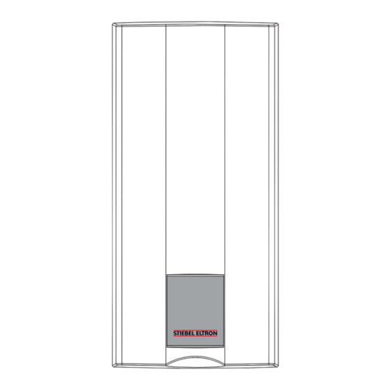
Summary of Contents for Steibel Eltron HDB-E 13 AU
- Page 1 OPERATION AND INSTALLATION Electronically controlled comfort instantaneous water heater » HDB-E 13 AU » HDB-E 18 AU » HDB-E 27 AU...
-
Page 2: Table Of Contents
CONTENTS | SPECIAL INFORMATION SPECIAL INFORMATION SPECIAL INFORMATION OPERATION General information �����������������������������������������3 - The appliance may be used by children aged 3 Safety instructions ����������������������������������������������� 3 Other symbols in this documentation ����������������������� 3 and older and persons with reduced physical, Units of measurement ������������������������������������������ 3 sensory or mental capabilities or a lack of ex- Safety ����������������������������������������������������������3 perience and know-how, provided that they... -
Page 3: General Information
OPERATION General information OPERATION f This symbol indicates that you have to do something. The ac- tion you need to take is described step by step. Units of measurement General information Note All measurements are given in mm unless stated oth- The chapter "Operation"... -
Page 4: Appliance Description
OPERATION Appliance description Appliance description Troubleshooting Problem Cause Remedy The appliance heats potable water that flows through it. The The appliance will not There is no power. Check the fuses/MCBs in heater starts automatically, as soon as a DHW valve is opened start despite the DHW your fuse box/distribu- and the start-up volume has been reached. -
Page 5: Installation
INSTALLATION Safety INSTALLATION Test for delivery temperature performance The appliance is to be tested according to AS 3498 as a 50 °C- limited water heater. The option 1 illustrated in figure A.1 of the Appendix A applies to the appliance. Safety Valve 1 Only a qualified contractor should carry out installation, commis- sioning, maintenance and repair of the appliance. -
Page 6: Preparation
INSTALLATION Preparation Preparation Water installation f Flush the water line thoroughly. Installation location Taps/valves f Use appropriate pressure-tested taps. Open vented taps are Material losses not permissible. Install the appliance in a room free from the risk of frost. Permissible water line materials f Always install the appliance vertically and near the draw-off point. -
Page 7: Installation
INSTALLATION Installation 10. Installation Fitting the wall mounting bracket Standard installation - Electrical connection in the lower section of the appliance for installation on unfinished walls - Water connection for installation on finished walls For further installation options, see chapter "Installation / Installation options": - Electrical connection from above on unfinished walls - Large conductor cross-section for electrical connection from... - Page 8 INSTALLATION Installation f Push the fixing toggle on to the threaded stud of the wall mounting bracket. f Push the back panel firmly against the wall. Lock the fixing toggle by turning it 90° clockwise. 1 Flow limiter 2 Plastic profile washer f Fit the flow limiter or the plastic profile washer.
-
Page 9: Completing The Installation
INSTALLATION Installation 10.2 Completing the installation Making the electrical connection f Open the shut-off valve in the cold water inlet line. WARNING Electrocution Carry out all electrical connection and installation work Fitting the cover guides for the appliance cover in accordance with relevant regulations. WARNING Electrocution The connection to the power supply must be in the form of a permanent connection in conjunction with the re-... -
Page 10: Commissioning
INSTALLATION Commissioning 11. Commissioning 12. Appliance shutdown f Isolate all poles of the appliance from the power supply. WARNING Electrocution f Drain the appliance (see chapter "Installation / Commissioning must only be carried out by a qualified Maintenance"). contractor in accordance with safety regulations. 13. -
Page 11: Water Installation On Unfinished Walls
INSTALLATION Alternative installation methods f Slide the cable grommet over the power cable. Use the installation aid supplied in the standard delivery. If the cross-section is > 6 mm², enlarge the hole in the cable grommet. f Push the cable grommet into the back panel. Click the cable grommet into place. -
Page 12: Troubleshooting
INSTALLATION Troubleshooting 14. Troubleshooting WARNING Electrocution In order to check the appliance it must be connected to the power supply. 14.1 Indicator options for LED diagnostic traffic light Indicator options Illuminates in the event of a fault Yellow Illuminates during heating operation Green Flashing: Appliance connected to power supply 14.2 Fault table... -
Page 13: Maintenance
INSTALLATION Maintenance 15. Maintenance 16. Specification 16.1 Dimensions and connections WARNING Electrocution Before any work on the appliance, disconnect all poles from the power supply. Draining the appliance You can drain the appliance for maintenance work or to protect it from frost. CAUTION Burns Hot water may escape when you drain the appliance. -
Page 14: Dhw Output
INSTALLATION Specification 16.3 DHW output 16.6 Fault conditions The DHW output is subject to the mains voltage, the appliance's In the event of a fault, loads up to a maximum of 95 °C at a pres- connected load and the cold water inlet temperature. The rated sure of 1.2 MPa can occur temporarily in the installation. -
Page 15: Data Table
INSTALLATION | ENVIRONMENT AND RECYCLING Specification 16.7 Data table HDB-E 13 AU HDB-E 18 AU HDB-E 27 AU 237749 237750 237751 Electrical data Rated voltage Rated output 12.2 13.5 14.5 16.2 19.4 23.5 Rated current 18.5 19.5 20.2 24.7 35.6 37.7... - Page 16 WARRANTY Who gives the warranty We will arrange a suitable time with you to inspect and test the unit. The warranty is given by Stiebel Eltron (Aust) Pty Ltd (A.B.N. 82 066 271 083) of 294 Salmon Street, Port Melbourne, Victoria, 3207 Warranty exclusions (“we”, “us”...
- Page 17 NOTES www.stiebel-eltron.com HDB-E AU |...
- Page 18 NOTES |HDB-E AU www.stiebel-eltron.com...
- Page 19 NOTES www.stiebel-eltron.com HDB-E AU |...
- Page 20 Deutschland Verkauf Tel. 05531 702-110 | Fax 05531 702-95108 | info-center@stiebel-eltron.de STIEBEL ELTRON GmbH & Co. KG Kundendienst Tel. 05531 702-111 | Fax 05531 702-95890 | kundendienst@stiebel-eltron.de Dr.-Stiebel-Straße 33 | 37603 Holzminden Ersatzteilverkauf Tel. 05531 702-120 | Fax 05531 702-95335 | ersatzteile@stiebel-eltron.de Tel.


Need help?
Do you have a question about the HDB-E 13 AU and is the answer not in the manual?
Questions and answers