
Subscribe to Our Youtube Channel
Related Manuals for Baudouin 12M26 Series


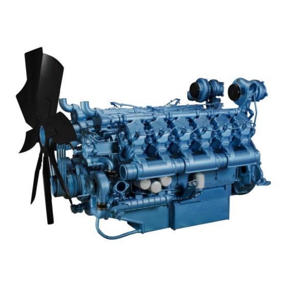
Summary of Contents for Baudouin 12M26 Series
- Page 1 Service Manual of 12M26 Series Diesel Engine for Land Power Generators Service Manual of 12M26 Series Diesel Engine for Land Power Generators...
- Page 2 Service Manual of 12M26 Series Diesel Engine for Land Power Generators Foreword This series diesel engine features the advantages of excellent technical indicators (compact structure, reliable operations, and high power performance, economy, and emission), rapid start, simple operations, convenient maintenances, and especially advanced emission indicator that meet the international advanced emission standards.
- Page 3 Service Manual of 12M26 Series Diesel Engine for Land Power Generators Special Notice Before the operations, the operator of the diesel engine must carefully read this maintenance manual and strictly abide by the operation and maintenance practices specified in the operation and service manual.
-
Page 4: Table Of Contents
Service Manual of 12M26 Series Diesel Engine for Land Power Generators Contents Chapter I General Information ....................1 External View of the Diesel Engine ................1 Model Meaning of Diesel Engine ................. 3 Basic parameters of diesel engine ................. 3 Operation Notice for New Diesel Engine .............. - Page 5 Service Manual of 12M26 Series Diesel Engine for Land Power Generators Overview ........................30 4.1.1 Danger signs ....................... 30 4.1.2 Safety signs ......................31 4.1.3 Tools ........................31 4.1.4 Precautions for health protection ................ 32 4.1.5 Environmental protection measures ..............33 4.1.6...
- Page 6 Service Manual of 12M26 Series Diesel Engine for Land Power Generators 4.10.3 Malfunction diagnosis and troubleshooting of charging system ....126 4.10.4 Generator ......................131 Annex A Recommended Torque for Standard Bolts ............... 136 Annex B Recommended Torque for Hollow Bolts ..............137 Appendix C Fit Clearances for Main Parts of Diesel Engine ..........
-
Page 7: Chapter I General Information
Service Manual of 12M26 Series Diesel Engine for Land Power Generators Chapter I General Information 1.1 External View of the Diesel Engine Front end Figure 1-1 Front exterior view of 12M26 series diesel engine 1 Water pump, 2 alternator, 3 Manual engine oil pump, 4 Diesel engine water outlet port (to... - Page 8 Service Manual of 12M26 Series Diesel Engine for Land Power Generators Right end Figure 1-3 Right side of 12M26 diesel engine 17 Fuel filter, 18 Ventilator Rear end Figure 1-4 Rear side of 12M26 diesel engine 19 Fuel pump...
-
Page 9: Model Meaning Of Diesel Engine
Service Manual of 12M26 Series Diesel Engine for Land Power Generators 1.2 Model Meaning of Diesel Engine Emission certification instructions Speed instructions Typical generator output (ESP)/KVA G-drive: First letter of generator Displacement per cylinder Baudouin series No. of cylinder 1.3 Basic parameters of diesel engine... -
Page 10: Operation Notice For New Diesel Engine
Service Manual of 12M26 Series Diesel Engine for Land Power Generators 1.4 Operation Notice for New Diesel Engine Maintenance period of diesel engine First maintenance (P) (30~50) running hours of new engine Level 1 maintenance (WD1) Every 250 running hours of diesel engine... - Page 11 Service Manual of 12M26 Series Diesel Engine for Land Power Generators position. When the diesel engine is running in an enclosed environment, keep well ventilated to ensure that the exhaust gas is drained to the open air. Adding of engine oil (1) The engine oil shall meet the specification;...
-
Page 12: Preparations Before Start
Service Manual of 12M26 Series Diesel Engine for Land Power Generators 1.7 Preparations before Start Check the coolant level. Check the coolant level. If the coolant is insufficient, add coolant. If the diesel engine remains hot, do not add a great deal of coolant. Dramatic temperature change could cause damage to the parts. -
Page 13: Running Of Diesel Engine
Service Manual of 12M26 Series Diesel Engine for Land Power Generators During the working of engine, both “oil pressure warning lamp” and the "battery power” indicator lamps are off. All indicator lamps are off during normal running of engine. In event of abnormality, the “horn” will issue warning tone. -
Page 14: Stop Of Diesel Engine
Service Manual of 12M26 Series Diesel Engine for Land Power Generators engine for troubleshooting. The operator shall understand the following characteristics of the engine: Low fuel consumption at the maximum torque. Increase in engine speed will result in that in fuel consumption. - Page 15 Service Manual of 12M26 Series Diesel Engine for Land Power Generators important for a turbocharged diesel engine. The bearings and oil seals in the turbocharger are subject to the influence of the high temperature exhaust gas. This heat is carried away by the circulating engine oil during the running of the diesel engine.
-
Page 16: Chapter Ii Maintenance Guide
Do not check the oil level while the diesel engine is running. It’s prohibited to mix the Baudouin special engine oil with any other manufacturer's oil. For the added volumes of engine oil and numbers of filters of Baudouin Power engines, see Table 2-2. -
Page 17: Engine Coolant
The freezing point specification for Baudouin special coolant includes -25ºC, -35ºC, and -40ºC. Please choose Baudouin special coolant of different freezing points based on the local environmental temperature in such manner that the freezing point is less than local air temperature by approximately 10ºC, with reference to Table 2-3. - Page 18 Service Manual of 12M26 Series Diesel Engine for Land Power Generators List of locations for Mark Main use application of sealant Supplement Flywheel cover bolt Camshaft thrust plate bolt Camshaft timing gear bolt Bolt, intermediate idler Bolt, front end cover Bolt, engine oil filter base It’s applied onto the...
-
Page 19: Daily Maintenance
Service Manual of 12M26 Series Diesel Engine for Land Power Generators 2.2 Daily maintenance 2.2.1 Daily service Check the coolant level, engine oil level, and fuel level. Check the lubricating points for grease insufficiency; Check for oil, coolant or air leakage;... - Page 20 Service Manual of 12M26 Series Diesel Engine for Land Power Generators Check for presence of water, gas, and oil leakages. The whole engine shall be free of water, air, and oil leakage. Check the fan. Figure: Visually check the blades of fan for presence of damage and check connecting bolts for secure fastening.
-
Page 21: Level-Specific Maintenance
Service Manual of 12M26 Series Diesel Engine for Land Power Generators Belt tensioner Figure 2-3 Check the belt Check whether exhaust gas has a normal color. The normal color of exhaust gas is light grey. Upon detection of change in color, check and solve the cause. - Page 22 Service Manual of 12M26 Series Diesel Engine for Land Power Generators Oil dipstick Engine oil filler port Drain plug Figure 2-4 Filler Port, Drain Plug and Filter of Engine Oil Replace engine oil filter or filter element. Replace the engine oil filter. Steps: A.
- Page 23 Service Manual of 12M26 Series Diesel Engine for Land Power Generators Valve clearance is 0.3 Figure 2-5 Adjustment of valve clearance C. Using the feeler gauges, check the clearance between Valve Bridge top and valve rocker arm (Table 2-1). If the clearance is too large or too small, adjust the adjustment bolt on the rocker to meet the above-mentioned clearance requirement.
- Page 24 Service Manual of 12M26 Series Diesel Engine for Land Power Generators Table 2-7 Adjustable Valves of Cylinders in the Compression Stroke B1 cylinder B6 cylinder cylinder cylinder cylinder cylinder Intake Intake Exhaust Intake Exhaust Non-adjustable B1 cylinder exhaust valves valve...
- Page 25 Service Manual of 12M26 Series Diesel Engine for Land Power Generators Intake pipe Exhaust pipe Figure 2-8 Intake and exhaust pipe Check the air filter element. The maximum intake resistance of diesel engine is 7kPa; Check the maximum intake resistance only when the diesel engine is running at rated speed under full load.
-
Page 26: Maintenance For Long-Term Storage Of Diesel Engine
Service Manual of 12M26 Series Diesel Engine for Land Power Generators Figure 2-9 Cleaning of Air Filter Element Caution: Do not blow through the filter paper, Do not clean the filter paper by water or oil, or Do not clap or knock the filter element forcibly. -
Page 27: Chapter Iii Typical Malfunctions And Troubleshooting Of Diesel Engine
Chapter III Typical Malfunctions and Troubleshooting of Diesel Engine 12M26 series diesel engine is designed and manufactured under strict quality assurance system and each delivered diesel engine passed the specified tests. In addition, the diesel engine is a kind of high precision machinery and the long-term guarantee of its functionality is closely related to the normal maintenances. -
Page 28: General Malfunction Causes And Troubleshooting Of Diesel Engine
Service Manual of 12M26 Series Diesel Engine for Land Power Generators Comparison method: For some assemblies or parts, the replacement method is adopted to determine the presence of malfunction. Note: 1. Judging the malfunction cause of diesel engine is a really precise work. Before the... -
Page 29: Low Power
Service Manual of 12M26 Series Diesel Engine for Land Power Generators Disassemble the filter body, remove internal contaminant (2) Blockage of fuel filter. and water, and when necessary replace filter element. (3) Poor fuel quality and high water Clean filter and replace fuel... -
Page 30: Excessive Fuel Consumption
Service Manual of 12M26 Series Diesel Engine for Land Power Generators (16) Wear and breakage of piston rings and Replace worn parts or overhaul the engine excessive gap of bearing shells (17) Wear or scuffing of cylinder sleeve or Repair or replace piston 3.2.4 Excessive fuel consumption... -
Page 31: White Or Blue Exhaust Gas
Service Manual of 12M26 Series Diesel Engine for Land Power Generators (6) Insufficient pressure turbocharger Check and solve leaks at pipeline connections. system (7) Abnormal working of turbocharger Check and replace assembly (8) Damage and air leakage of inter-cooler Replace or repair... -
Page 32: Unstable Speed
Service Manual of 12M26 Series Diesel Engine for Land Power Generators 3.2.8 Unstable speed Cause Troubleshooting (1) Poor fuel quality, with water or paraffin Replace fuel content Check sealing performance of fuel pipes and (2) Air ingress of fuel suction pipe... -
Page 33: High Coolant Temperature
Service Manual of 12M26 Series Diesel Engine for Land Power Generators and ensure that the flashing point of engine oil is no less than that of new oil 3.2.10 High coolant temperature Cause Troubleshooting (1) Under-low level in water tank... -
Page 34: Excessive Noise
Service Manual of 12M26 Series Diesel Engine for Land Power Generators 3.2.12 Excessive noise Cause Troubleshooting (1) Poor fuel quality Replace fuel (2) Under-low coolant temperature Check thermostat and replace when necessary. (3) Incorrect valve or fuel supply timing Check, repair, and adjust... - Page 35 Service Manual of 12M26 Series Diesel Engine for Land Power Generators (2) Wear of bearing bushing Replace assembly Clean electric brush surfaces or replace (3) Poor contact of electric brush electric brush Remove oil dirt and polish with sand (4) Dirty or burnt commutator...
-
Page 36: Chapter Iv Dismantling And Assembling Of Engine
Service Manual of 12M26 Series Diesel Engine for Land Power Generators Chapter IV Dismantling and Assembling of Engine 4.1 Overview During dismantling and assembling of diesel engine, please follow operating instructions in this manual strictly and pay attention to operation steps containing danger and safety marks, so as to ensure personal safety and avoid accidents. -
Page 37: Safety Signs
Service Manual of 12M26 Series Diesel Engine for Land Power Generators 4.1.2 Safety signs Table 4-1 Safety signs Picture Definition Wear hand protectors Wear ear protectors Wear eye protectors Wear a head protector Wear foot protectors Wear protective mask Wear protective clothing... -
Page 38: Precautions For Health Protection
Service Manual of 12M26 Series Diesel Engine for Land Power Generators Picture Definition 2.5mm hex wrench 5mm hex wrench 8mm socket Slotted screwdriver Special tool 10mm flat hexagon wrench Should any method or tool used is not recommended in this manual, the user must first ensure... -
Page 39: Environmental Protection Measures
Failure to follow relevant instructions given in this manual may result in serious accidents, even endangering the operator's life. Baudouin Power Co., Ltd. cannot foresee all potential risks. Similarly, guidelines and instructions specified in this manual are not exhaustive. -
Page 40: Cylinder Head Subassembly
Service Manual of 12M26 Series Diesel Engine for Land Power Generators uniform. Before working, please check whether corresponding protection equipment (goggles, gloves, shoes, masks, working uniform, helmet, etc.) are within effective life. Do not use faulty or unsuitable tools. Stop the diesel engine during maintenance or service. -
Page 41: Assembling Procedures
Service Manual of 12M26 Series Diesel Engine for Land Power Generators 10) Disassemble the cylinder head and the cylinder head gasket. 11) Disassemble the inner and outer springs of valves, spring upper and lower seats of intake and exhaust valves, valve collets, and valves. Refer to disassembling instruction of valve mechanism for details. - Page 42 Service Manual of 12M26 Series Diesel Engine for Land Power Generators Washer Hexagon head screw plug Thermostat bracket Thermostat bolt Connecting Thermostat pipe bracket O-RING Hexagon flange bolt Hexagon flange Hexagon flange bolt bolt Connecting Rubber ring Water outlet pipe...
- Page 43 Service Manual of 12M26 Series Diesel Engine for Land Power Generators Lifting rings Figure 4-2 Assembling of engine rings 4.2.4.3 Cylinder head cover [Disassembling] Loosen the cylinder head cover bolts in turn and vertically take out the cylinder head cover and cylinder head cover gasket, as shown in the figure.
- Page 44 Service Manual of 12M26 Series Diesel Engine for Land Power Generators 2) Wipe clean the top face of cylinder head and assemble cylinder head gaskets correctly in turn. 3) Apply oil to the rubber O-rings, install O-rings into grooves of cylinder head cover, wipe clean the cylinder head cover, and assemble the cylinder head cover onto the cylinder head in correct sequence.
- Page 45 Service Manual of 12M26 Series Diesel Engine for Land Power Generators gaskets. [Assembling] The assembling procedure is in reverse sequence of the disassembling procedure. Hollow bolt Lubricating oil pipe Flange bolt Hollow bolt Pipe clamp Oil inlet pipe Hollow bolt...
- Page 46 Service Manual of 12M26 Series Diesel Engine for Land Power Generators 6) Dismantle the intake and exhaust valves by referring to Instructions for Dismantling of Valve Mechanism; 7) Disassemble the valve stem sealing sleeve. Cylinder head main bolt Cylinder head auxiliary bolt...
- Page 47 Service Manual of 12M26 Series Diesel Engine for Land Power Generators The valve sinkage is the vertical distance from the bottom surface of the valve to the bottom surface of the cylinder head, and the difference between the valve sinkage measurement value and the required valve sinkage value can reflect degree of wear of the valve and valve seat.
- Page 48 Service Manual of 12M26 Series Diesel Engine for Land Power Generators Figure 4-7 Inside Micrometer ④ Cylinder head gasket In case of gas leakage, water leakage, fuel leakage and other problems at the cylinder head gasket, it is required to inspect the cylinder head gasket and replace it wherever necessary.
- Page 49 Service Manual of 12M26 Series Diesel Engine for Land Power Generators ③ Use the guide rods to screw them into the cylinder head bolt holes. ④ The cylinder head gasket shall be free of distortion, deformation, and damage. (3) Loosen the cylinder cover main bolts.
- Page 50 Service Manual of 12M26 Series Diesel Engine for Land Power Generators Figure 4-11 Valve stem sealing sleeve [Disassembling] To disassemble the valve stem sealing sleeve, use the special tooling or use pliers to clamp the outer walls of valve stem sealing sleeve and rotate upward to lift out the valve stem sealing sleeve.
-
Page 51: Engine Block Group
Service Manual of 12M26 Series Diesel Engine for Land Power Generators 4.3 Engine Block Group 4.3.1 Flywheel cover 4.3.1.1 Parts Figure 4-12 Disassembling diagram of flywheel cover Table 4-4 List of flywheel cover ADJUSTMENT POINTER POINTER PLATE Hexagon socket cylindrical head screw... - Page 52 Service Manual of 12M26 Series Diesel Engine for Land Power Generators 4.3.1.2 Disassembling It’s in reverse to the installation sequence 4.3.1.3 Dismantle It’s in reverse to the installation sequence 4.3.1.4 Checking Check for completeness of parts against the table of parts. Check the statuses of rear end plate, flywheel cover, and cylinder block and ensure that all junction surfaces are free of burrs, oil dirt, and knocking damages.
-
Page 53: Cylinder Block
Service Manual of 12M26 Series Diesel Engine for Land Power Generators 4.3.1.8 Special tools Oil seal pressing tooling, oil seal alignment tooling, copper hammer, flywheel housing guide bar, and flywheel housing hoist. 4.3.2 Cylinder block 4.3.2.1 Parts Figure 4-13 Diagram of cylinder block parts... - Page 54 Service Manual of 12M26 Series Diesel Engine for Land Power Generators Figure 4-14 Diagram of cylinder block parts Table 4-6 List of cylinder block parts...
- Page 55 Service Manual of 12M26 Series Diesel Engine for Land Power Generators 4.3.2.2 Dismantle It’s in reverse to the installation sequence of diesel engine. 4.3.2.3 Checking 1) Check all machined surfaces of cylinder block. All machined surfaces shall be free of burrs, oil dirt, and knocking damage.
-
Page 56: Oil Sump And Piston Cooling Nozzle Parts
Service Manual of 12M26 Series Diesel Engine for Land Power Generators Automatic tightening: 200N.m for first step and (575±25) N.m for second step. 6) Pre-tighten the auxiliary bolts of main bearing cap uniformly on the side A in sequence to (270±20) N.m. - Page 57 Service Manual of 12M26 Series Diesel Engine for Land Power Generators Figure 4-16 Diagram of oil sump parts Table 4-9 Diagram of oil sump parts list Name Name Oil sump Washer Oil dipstick tube Hexagon head screw plug Pipe connector...
- Page 58 Service Manual of 12M26 Series Diesel Engine for Land Power Generators beneath the oil drainage plug of the oil sump, and use a screw plug wrench to loosen the oil drainage plug to empty oil. 2) Disassemble the oil dipstick assembly. Notice not to damage the oil dipstick during disassembling.
-
Page 59: Crank Connecting Rod Mechanism
Service Manual of 12M26 Series Diesel Engine for Land Power Generators Tightening torque is 40N.m. 4.3.3.3 Torque specification Tightening torque for hexagon socket cylindrical head screws: 60~66N.m Tightening torque for hollow bolts of piston cooling nozzle: 40N.m 4.4 Crank Connecting Rod Mechanism 4.4.1 Crankshaft and flywheel subassembly... - Page 60 Service Manual of 12M26 Series Diesel Engine for Land Power Generators Figure 4-17 Crankshaft assembly 2) Check the junction surface between crankshaft and flywheel and ensure that the junction surface is free of burr, oil dirt, and damage. 3) Knock the locating pin into the front pinhole of crankshaft to the end and tighten the flywheel bolts as per the following requirements.
- Page 61 Service Manual of 12M26 Series Diesel Engine for Land Power Generators Figure 4-19 Flywheel assembly 5) Rotate for several turns, check the axial clearance, and ensure the flexible rotation of crankshaft without obstruction. Ensure that the axial clearance of the crankshaft is 0.1~0.346.
-
Page 62: Piston And Connecting Rod
Service Manual of 12M26 Series Diesel Engine for Land Power Generators Figure 4-20 Crankshaft and pulley subassembly 1. M16×75 Hexagon head bolts with flange 2. M14×65 Hexagon head bolts with flange 3. Crankshaft pulley 4. Shock absorber 5. M12×30 Hexagon head bolts with flange 6. Turning device 4.4.2 Piston and connecting rod... - Page 63 Service Manual of 12M26 Series Diesel Engine for Land Power Generators 4.4.2.2 Breakdown Trapezoidal barrel-face ring Taper-face ring Coil spring loaded Piston control ring Piston pin Retainer ring for hole Connecting rod body Connecting upper bearing shell Connecting lower bearing shell...
- Page 64 Service Manual of 12M26 Series Diesel Engine for Land Power Generators around the oil orifices of small end bearing shell. 2) Mark one end of the connecting rod bolt with the cylinder number, and the end of the piston toward the flywheel with the cylinder number.
- Page 65 Service Manual of 12M26 Series Diesel Engine for Land Power Generators 1st gas ring 2nd gas ring Horizontal direction of piston pin Oil ring Figure 4-22 Opening direction of piston ring 6) Ensure that the piston rings are installed parallelly in the ring grooves, without any distortion.
- Page 66 Service Manual of 12M26 Series Diesel Engine for Land Power Generators crank arm. Before assembling, notice to face the oil orifice of piston towards the nozzle. While lowering the connecting rod, prevent collision with nozzle and crank arm. After the assembling, ensure that the opening of connecting rod bolt faces towards the observation hole.
-
Page 67: Valve Mechanism
Service Manual of 12M26 Series Diesel Engine for Land Power Generators Figure 4-25 Feeler gauge 4.5 Valve mechanism 4.5.1 Rocker arm 4.5.1.1 Rocker overview The rocker is actually a double armed lever (as shown in the Figure 4-26) and is functioned to change the direction of the force transmitted from the push rod and apply it to the valve stem end to drive the valves. - Page 68 Service Manual of 12M26 Series Diesel Engine for Land Power Generators 4.5.1.3 Disassembling of rocker Open the rocker cover. After the checking, loosen the screws of rocker seat, lightly take out the rocker, and add the markings to prevent the confusion among the rockers of different cylinders.
-
Page 69: Camshaft
Service Manual of 12M26 Series Diesel Engine for Land Power Generators 2) Check and adjust the clearances of intake and exhaust valves. 3) Check the phase angles for opening of intake valve and closing of exhaust valve for 1st cylinder and record. - Page 70 Service Manual of 12M26 Series Diesel Engine for Land Power Generators 4.5.2.3 Disassembling of camshaft On the working bench for installation and dismantling of the engine, turn the crankshaft to enable the camshaft timing gear to be at the top dead center of the 1st cylinder. Disassemble the camshaft timing gear, camshaft bushing, and camshaft and guard the camshaft against collision.
- Page 71 Service Manual of 12M26 Series Diesel Engine for Land Power Generators measure the axial clearance of camshaft and ensure that the axial clearance is 0.1~0.25mm. Install the camshaft cover plate flange on the flywheel end. The tooling and auxiliary materials used for the installation of camshaft are listed in Table 4-13.
-
Page 72: Timing Gear
Service Manual of 12M26 Series Diesel Engine for Land Power Generators 4.5.3 Timing gear 4.5.3.1 Gear train diagram Fuel injection pump gear Intermediate gear Camshaft gear Crankshaft gear Figure 4-28 Diagram of gear train 4.5.3.2 Disassembling 1) Complete the disassembling of front accessories (including water pump and pulley) and the front end cover plate. - Page 73 Service Manual of 12M26 Series Diesel Engine for Land Power Generators and then disassemble six M10 connecting bolts between camshaft gear and fuel injection pump intermediate gear to separate them. 4) Inspect the mark on the mounting bolt of the injection pump gear and confirm whether the bolt turns or not.
- Page 74 Service Manual of 12M26 Series Diesel Engine for Land Power Generators Figure 4-29 Installation of gear 3) Rotate the crankshaft to place the marking “.” of crankshaft gear with respect to the vertical plane, install the camshaft gear subassembly onto the camshaft, and align the marking “N”...
- Page 75 Service Manual of 12M26 Series Diesel Engine for Land Power Generators Figure 4-30 Installation of gear Tighten the camshaft gear and camshaft by six M10 hexagon head bolts. Check the backlash between crankshaft gear and camshaft gear. The backlash range is 0.09~0.15.
-
Page 76: Intake And Exhaust System
Service Manual of 12M26 Series Diesel Engine for Land Power Generators Figure 4-31 Installation of gear 4.5.3.5 Torque specification Intermediate gear bolts: Apply sealant uniformly to the threads and tighten to (75±5) N.m. Camshaft gear bolts: Apply sealant uniformly to the threads and tighten to (70±5) N.m. - Page 77 Service Manual of 12M26 Series Diesel Engine for Land Power Generators Figure 4-32 Intake diagrammatic sketch 4. The combusted exhaust gas is supplied to the exhaust pipe via exhaust valve. 5. The exhaust gas is supplied to the turbine of turbocharger via exhaust pipe.
-
Page 78: Turbocharging System
Service Manual of 12M26 Series Diesel Engine for Land Power Generators 4.6.2 Turbocharging system 4.6.2.1 Maintenance To ensure the reliable and normal running of turbocharger and engine, the maintenance in line 1) Daily maintenance 2) Inspect whether the connecting pipe between the turbocharger and the engine is loosened or not, and if any, eliminate the problem. - Page 79 Service Manual of 12M26 Series Diesel Engine for Land Power Generators Figure 4-33 Diagram for measurement of axial clearance 3) Inspection of axial clearance of the air compressor impeller Press the air compressor impeller by hand in axial direction, and use a plug gauge to measure the minimum and maximum clearance between the air compressor impeller and air compressor scroll, shown as following figure: This value should be within 0.4mm~0.8mm, and in case of...
- Page 80 Service Manual of 12M26 Series Diesel Engine for Land Power Generators hammer. It’s prohibited to collide the impellor blades with the housing or loosen the shaft end nut. 2) Wipe away the oil dirt from the impellor passage and housing inner chamber by gasoline.
- Page 81 Service Manual of 12M26 Series Diesel Engine for Land Power Generators crankcase. 4) The capacity of the diesel engine intake pipe shall be as large as possible, in order to reduce the intake pressure pulsation. The air filter must have appropriate capacity to prevent the excessive inlet pressure loss of the compressor.
- Page 82 Service Manual of 12M26 Series Diesel Engine for Land Power Generators troubleshooting are listed in Table 4-14. Table 4-14 General malfunctions and troubleshooting of turbocharger Symptom Cause Troubleshooting 1. Blockage of air filter and reduced intake Clean the air filter.
- Page 83 Service Manual of 12M26 Series Diesel Engine for Land Power Generators turbocharger 2. Eliminated gap and friction between Replace bearing or entire impeller outer arc and housing turbocharger Due to damage of bearing 3. Deteriorated dynamic balance precision due Clean and verify...
-
Page 84: Turbocharger
Service Manual of 12M26 Series Diesel Engine for Land Power Generators Name Clearance Unit Front clearance compressor 0.505~1.075 in axial direction impellor 0.467~0.995 in normal direction Back clearance compressor 0.59~0.98 impellor 0.801~1.319 in axial direction Front clearance of turbine impellor 0.538~0.886 in normal direction... - Page 85 Service Manual of 12M26 Series Diesel Engine for Land Power Generators Turbine end clamping band Turbine shaft Spacing sleeve assembly Volute pressure plate Shaft end nut Thrust plate Compressor back plate Oil slinger Floating bearing Floating bearing retainer Compressor volute...
- Page 86 Service Manual of 12M26 Series Diesel Engine for Land Power Generators 4) Take out the turbine shaft. (1) Hold the thermal shield lightly by hand and withdraw the turbine shaft. Notice: If it’s difficult to withdraw the turbine shaft, lightly knock the compressor end by a wood hammer.
- Page 87 Service Manual of 12M26 Series Diesel Engine for Land Power Generators Lubricating oil status 1) Turbine shaft 1, journal location, and thrust bearing (such as wear, seizure, and oil slinger 2 discoloration) 2) Floating bearing 5 and thrust bearing 6...
- Page 88 Service Manual of 12M26 Series Diesel Engine for Land Power Generators d) Others 1) Clean other parts by diesel. 2) Blow the lubricating oil ways by compressed air. 3) Take special cautions not to damage or corrode the parts. 4.6.3.5 Checking 1) Compressor seat Check the compressor seat for contact trace with compressor impellor, for surface damage, and for indentation or cracking at junction surface.
- Page 89 Service Manual of 12M26 Series Diesel Engine for Land Power Generators Figure 4-37 Schematic diagram 6) Thrust bearing, engine oil slinger, and thrust bearing Check every part for wear, surface damage, and discoloration. Upon detection of any above-mentioned damage, replace with new parts, even if they are still within the wear limit.
- Page 90 Service Manual of 12M26 Series Diesel Engine for Land Power Generators Inner diameter (C):8.04mm RHB31…………Outer diameter (D):9.93mm Inner diameter (C):6.29mm 8) Bearing seat 15 (1) Check the surfaces of bearing seat castings for oxidizing falloff, deterioration, indentation, and cracking. Upon detection of such defect, replace with new parts.
- Page 91 Service Manual of 12M26 Series Diesel Engine for Land Power Generators (2) Check the installation dimensions (H1 and H2) of seal ring on the compressor side. If beyond wear limit, replace with new seal ring. Figure 4-39 Measurement drawing H2:10.05mm RHB51………H1:12.45mm,...
- Page 92 Service Manual of 12M26 Series Diesel Engine for Land Power Generators (1) Install the floating bearing. 1) Install the inner retainer ring into bearing seat by pliers. 2) Install the floating bearing to the bearing seat. 3) Install the outer retainer ring into bearing seat by pliers.
- Page 93 Service Manual of 12M26 Series Diesel Engine for Land Power Generators (5) Install the compressor impellor 1) Attach the compressor impellor 18 to the turbine shaft 1. 2) Fix the turbine end of turbine shaft 1 by a 10mm socket and tighten the shaft end nut 19.
-
Page 94: Fuel System
Service Manual of 12M26 Series Diesel Engine for Land Power Generators 4.6.3.7 Installation instruction of turbocharger Handling after assembling Strictly abide by the following installation instruction while installing the turbocharger to the engine or during the handling after reinstallation. Take special cautions to prevent the falling of foreign material into turbocharger. - Page 95 Service Manual of 12M26 Series Diesel Engine for Land Power Generators Figure 4-40 Composition diagram of fuel system 1-Fuel injector; 2-Gear fuel delivery pump; 3-Fuel injection pump; 4-Manual fuel delivery pump; 5-Fuel cutoff solenoid valve; 6-Fuel strainer; 7-Fuel strainer; 8-Fuel tank 4.7.1.1 Precautions for maintenance services...
-
Page 96: Fuel Filter
Service Manual of 12M26 Series Diesel Engine for Land Power Generators 4.7.1.2 Functional description The fuel system is functioned to inject the fuel of fixed volume into the cylinder at the fixed timing so that the fuel is combusted to power the running of diesel engine. The functions of the system parts are as below: Fuel strainer –... - Page 97 Service Manual of 12M26 Series Diesel Engine for Land Power Generators Fuel coarse filter Fuel fine filter Figure 4-41 Layout of fuel filter 4.7.2.1 Parts Manual pump Fuel coarse filter Fuel inlet Fuel outlet Fuel outlet Fuel inlet Fuel fine filter...
- Page 98 Service Manual of 12M26 Series Diesel Engine for Land Power Generators Water drainage valve Figure 4-43 Fuel filter water drainage valve 4.7.2.2 Breakdown Figure 4-44 Diagram of fuel filter parts Table 4-19 List of fuel filter Fuel filter bracket Hexagon socket head screws...
-
Page 99: Fuel Pump
Service Manual of 12M26 Series Diesel Engine for Land Power Generators 4.7.2.3 Checking Check the water level in the water collector of fuel strainer and drain the water once every 100 hours. Replace the fuel filter element once every 400 hours. - Page 100 Service Manual of 12M26 Series Diesel Engine for Land Power Generators 4.7.3.2 Breakdown P10 fuel injection pump is an enhanced inline fuel injection pump, featuring small volume and high fuel supply and carrying capacity. It’s mainly composed of pump body, pumping system, fuel volume control mechanism, and drive mechanism.
- Page 101 Service Manual of 12M26 Series Diesel Engine for Land Power Generators plunger via the engaged plunger control sleeve to change the relative position between plunger and the plunger sleeve so that the change extent of the relative position is used to adjust the fuel volume.
- Page 102 Service Manual of 12M26 Series Diesel Engine for Land Power Generators 4.7.3.3 Disassembling 4.7.3.3.1 Disassembling Before the disassembling, remove the external dusts and dirt, record the adjustment data, and disassemble as per the procedure below: 1) Fix the fuel injection pump assembly on special bench or vice bench.
- Page 103 Service Manual of 12M26 Series Diesel Engine for Land Power Generators Check the sliding performance of plunger by rotating and sliding downward the plunger. Upon detection of over-fast rotation or stagnation midway, replace the plunger. 2) Fuel outlet valve coupling Replace the fuel outlet valve and valve seat upon detection of damage or wear in their working surfaces.
- Page 104 Service Manual of 12M26 Series Diesel Engine for Land Power Generators 4.7.3.4 Assembling 4.7.3.4.1 Installation of fuel injection pump 1) Place the plunder sleeve on special tooling or vice, install the sealing gasket, fuel valve parts, fuel outlet valve spring, and fuel outlet valve spring seat, screw the fixing seat of fuel outlet valve, place the plunger into original plunger sleeve, and install the O-ring.
- Page 105 Service Manual of 12M26 Series Diesel Engine for Land Power Generators 4.7.3.4.2 Installation of electric speed regulator Perform the wiring and installation as per the figure below. Auxiliary power supply (10V) Speed regulation voltage input Name Speed controller Electromagnetic actuator...
- Page 106 Service Manual of 12M26 Series Diesel Engine for Land Power Generators Figure 4-48 Assembly of fuel injection pump 1) Install the fuel injection pump hub onto the fuel pump, with the hub marking facing upward. Align its marking with that of fuel pump, apply sealant 242 to the threads, and tighten to (250~300) N.m.
- Page 107 Service Manual of 12M26 Series Diesel Engine for Land Power Generators 12) Stagnation between actuator and fuel pump 12) Overhaul rack linkage 13) Broken actuator cable 13) Replace actuator cable 2. Insufficient horsepower 1) Early or delayed fuel injection timing...
-
Page 108: Cooling System
Service Manual of 12M26 Series Diesel Engine for Land Power Generators 4.8 Cooling System 4.8.1 Cooling circuit The diesel engine for land power generator only adopts the circulation of heat carrying fluid within an enclosed circuit. The major and minor circulations of the cooling system are controlled by the thermostat:... - Page 109 Service Manual of 12M26 Series Diesel Engine for Land Power Generators Gasket Thermostat Thermostat body Thermostat cover Figure 4-50 Breakdown diagram of thermostat Checking of thermostat Immerse the automatic thermostat in a water container. After heating, measure the water temperature and observe the temperatures of thermostat for consistency with the temperatures listed in the table below.
-
Page 110: Water Pump
2) Replace the O-ring of water pump with new one. 4.8.4 Fan The 12M26 series diesel engine for power generator adopts the steel fan with rigid drive mode. Depending on the needs of diesel engine for power generator, the reverse fan is adopted to... - Page 111 Service Manual of 12M26 Series Diesel Engine for Land Power Generators guarantee the cooling effect. 4.8.4.1 Parts The fan parts are as below: Figure 4-53 Diagram of fan Table 4-21 List of fan Chinese name Number of units Hexagon bolt...
- Page 112 Service Manual of 12M26 Series Diesel Engine for Land Power Generators specification 190N·m 10.9 Figure 4-54 Diagram of fan 4.8.4.3 Checking 4.8.4.3.1 Checking of fan Check the fan rivets for looseness, check the fan blades for bending, and ensure the normal...
- Page 113 Service Manual of 12M26 Series Diesel Engine for Land Power Generators Figure 4-55 Checking of fan 4.8.4.3.2 Check the poly V-belt Visually observe the poly V-belt for cracking and scratch and when necessary replace. Figure 4-56 Checking of poly V-belt...
-
Page 114: Lubrication System
Service Manual of 12M26 Series Diesel Engine for Land Power Generators 4.9 Lubrication System 4.9.1 Lubrication System Figure 4-57 Diagram of lubrication system Table 4-23 List of lubrication system Oil sump Drain plug Oil dipstick Strainer Oil pump Pressure limiting valve... - Page 115 Service Manual of 12M26 Series Diesel Engine for Land Power Generators Rocker lubricating oil pipe Oil inlet pipe of fuel injection pump Oil return pipe of fuel injection pump Oil return pipe Turbocharger oil inlet pipe Turbocharger oil return pipe...
- Page 116 Service Manual of 12M26 Series Diesel Engine for Land Power Generators During installation, the backlash of engine oil pump with the crankshaft gear is (0.15~0.2) The fastening bolts of the engine oil pump are in specification of M12 (grade 10.9). During installation, apply Loctite 242 to the thread surfaces to prevent vibration looseness and tighten to 110±5N.m.
- Page 117 Service Manual of 12M26 Series Diesel Engine for Land Power Generators circuits respectively. The engine oil filter is located on the side face of oil sump. Replace the centrifugal filter element. a. Loosen the top nut 5. b. Take out the intermediate filter cup 1.
- Page 118 Service Manual of 12M26 Series Diesel Engine for Land Power Generators Check the engine oil level and pre-lubricate the engine. Re-check the oil level and when necessary add sufficient oil. Ensure that the engine oil filters are free of oil leakage.
-
Page 119: Oil Cooler
Service Manual of 12M26 Series Diesel Engine for Land Power Generators marking of oil dipstick. Start and idle the engine and check the engine oil filters and drainage plug for oil leakage. Stop the engine, wait for approximately 5min for the engine oil to return from upper parts into oil sump, and check the oil level once again. -
Page 120: Startup System
Service Manual of 12M26 Series Diesel Engine for Land Power Generators screw The engine is fitted with two engine oil cooler, which located on the both sides of the engine. The engine oil is circulated by cooler and is cooled by engine coolant before being filtered. - Page 121 Service Manual of 12M26 Series Diesel Engine for Land Power Generators control levers on the fuel injection pump to ensure flexible motions. Before start, rotate the crankshaft of diesel engine for several turns. After the rotation without obstruction is confirmed, place the speed control lever of fuel injection pump in the middle position and turn on the power switch.
- Page 122 4.10.1.2 Function and operation descriptions 12M26 series diesel engine for power generator is started by electric starter motor. Under normal working condition, the starter motor converts the electric energy stored in the battery into mechanic energy to drive the running of engine at a speed high enough for successful start of the engine.
- Page 123 Service Manual of 12M26 Series Diesel Engine for Land Power Generators 4.10.1.2.2 Stop of Diesel Engine Avoid the stop of engine under full load. Before stopping the engine, reduce the load and speed and run the engine under idling or low-load condition for 3~5min to cool down the pistons, cylinder sleeves, bushings, shaft sleeves, and turbocharger for a sufficient time, in order to prevent the scuffing and bushing scratch.
-
Page 124: Starter
Service Manual of 12M26 Series Diesel Engine for Land Power Generators 4. After the start of engine, the starter motor doesn’t stop rotation when the starter motor switch is turned off. Cause Troubleshooting Return failure of switch Check and repair switch... - Page 125 Service Manual of 12M26 Series Diesel Engine for Land Power Generators 4.10.2.1.2 Model and classification In accordance with the regulations of the industry standard QC/T73-93 Preparation Method of Product Model for Automotive Electric Equipment of the People’s Republic of China, the...
- Page 126 Service Manual of 12M26 Series Diesel Engine for Land Power Generators Screw three M10×25 studs into flywheel cover by stud tooling and tighten the studs (As shown in Figure 1). Put the ring washer on the starter motor and place the starter motor vertical to the installation hole, pass the starter motor through the studs and install to the flywheel cover, and ensure the correct engagement of starter pinion (As shown in Figure 2).
- Page 127 Service Manual of 12M26 Series Diesel Engine for Land Power Generators Type 1 hexagon Starter Ring washer Standard spring washer Figure 4-68 Loose installation of starter motor Tighten 64N.m~76N.m 16mm wrench Figure 4-69 Tighten bolts as per specification 4.10.2.2.2 Wiring of starter motor The wiring of starter motor must be correct, secure, and safe.
- Page 128 Service Manual of 12M26 Series Diesel Engine for Land Power Generators Table 4-27ightening torques Screw Tightening torque Screw Tightening torque specification (N.m) specification (N.m) 2~2.5 13.5~15.8 8.4~10.5 24.7~27.5 4.10.2.2.3 Disassembling of starter motor To disassemble the steering pump, disassemble the bolts by a 16mm wrench, take out the nuts and washers, and lightly knock the housing by a rubber hammer (never knock by a hard object) to disassemble the starter motor.
- Page 129 Service Manual of 12M26 Series Diesel Engine for Land Power Generators Troubleshooting: Replace starter motor. Symptom 2: The starter motor is not rotating, but a clear and short “click” sound can be heard. Cause 1: Low voltage of battery. Checking: Under the stop state of engine, turn on the headlamp for 1~3min and then measure the battery voltage.
- Page 130 Service Manual of 12M26 Series Diesel Engine for Land Power Generators Troubleshooting: Correctly install the starter motor. If the starter motor gears are damaged, replace the starter motor. Cause 2: Excessive depletion of battery. Checking: Under the stop state of engine, turn on the headlamp for 1~3min and then measure the battery voltage.
- Page 131 Service Manual of 12M26 Series Diesel Engine for Land Power Generators Cause 3: Ablation of starter motor contact or damage of contact coil spring and soft or broken return spring of drive fork. Checking: Replace starter motor and perform start test.
-
Page 132: Malfunction Diagnosis And Troubleshooting Of Charging System
Service Manual of 12M26 Series Diesel Engine for Land Power Generators The original diameter of M93 series commutator is Ø35. The original diameter of M105 series commutator is Ø39. The electromagnetic switch and the starter relay are used continuously for 2 years (20,000 start cycles). - Page 133 Service Manual of 12M26 Series Diesel Engine for Land Power Generators during idling speed of engine. of engine and turns during high-speed running engine. ① If the alternator indicator lamp terminal a. Check whether charging voltage voltage is really low, it indicates low power of...
- Page 134 Service Manual of 12M26 Series Diesel Engine for Land Power Generators regulator is malfunctioned and needs to be replaced. ③ The lighting intensity of indicator lamp is normal, the indicator lamp turns on constantly after the engine is started, and the alternator output voltage is the battery voltage.
- Page 135 Service Manual of 12M26 Series Diesel Engine for Land Power Generators rise under heavy-load working condition, replace the wire or connector. ①Grind the wire lugs with oxidized surfaces and Check presence of high the housing surface for installation of grounding temperature bolt and reinstall.
- Page 136 Service Manual of 12M26 Series Diesel Engine for Land Power Generators alternator housing. ① Observe during the charging of battery c. Check battery normal whether the charging current varies greatly within working status. a short period (from 50A to below 10A). If not, the replacement of battery as soon as possible shall be considered.
-
Page 137: Generator
Service Manual of 12M26 Series Diesel Engine for Land Power Generators 4.10.3.5 Alternator noise Malfunction 4: Unstable charging voltage Vehicle Failure detection Troubleshooting symptom a. The fixing bracket of alternator Improve strength fixing is deformed or is too close to... - Page 138 Service Manual of 12M26 Series Diesel Engine for Land Power Generators ★ Warning: The loose belt will lead to “speed loss” of the alternator and cause the malfunctions such as insufficient power generation, battery depletion, stator burnout, and bearing damage. A new replacement belt must be re-tensioned after 5min running.
- Page 139 Service Manual of 12M26 Series Diesel Engine for Land Power Generators Generator installation position. 2. Loosen the automatic tensioner and disassemble the poly V-belt from alternator pulley. Generator Automatic tensioner 3. Disassemble the M12 and M10 4. The installation sequence for the mounting bolts of alternator.
- Page 140 Service Manual of 12M26 Series Diesel Engine for Land Power Generators alternator is malfunctioned. Tool: Test lamp. The procedure is shown in figure below. Turn on the power switch of the vehicle and connect the test lamp to the terminal B+ and E (negative) of the alternator.
- Page 141 Service Manual of 12M26 Series Diesel Engine for Land Power Generators Timely remove the dusts and oil dirt from alternator. Periodically check the wear status of alternator carbon brush and slip ring and when necessary remove the dusts adhered onto the slip ring by sand paper.
-
Page 142: Annex A Recommended Torque For Standard Bolts
Service Manual of 12M26 Series Diesel Engine for Land Power Generators Annex A Recommended Torque for Standard Bolts Recommended Torques for Standard Bolts Friction 0.125 (zinc plated) 0.14 (polished) coefficient Strength grade 10.9 12.9 10.9 12.9 Recommended torque (N·m) Bolt size 13.0... -
Page 143: Annex B Recommended Torque For Hollow Bolts
Service Manual of 12M26 Series Diesel Engine for Land Power Generators Annex B Recommended Torque for Hollow Bolts Recommended Torques for Hollow Bolts Recommended tightening Specification Head type torque (Nm) M8×1 7±1 Hexagon head 17±2 Hexagon head 13±2 (Copper bolt and small M10×1... -
Page 144: Appendix C Fit Clearances For Main Parts Of Diesel Engine
Service Manual of 12M26 Series Diesel Engine for Land Power Generators Appendix C Fit Clearances for Main Parts of Diesel Engine Theoretical Item value (mm) Main bearing clearance 0.122~0.202 Connecting rod bearing clearance 0.093~0.167 Crankshaft endplay 0.1~0.346 Connecting rod axial clearance 0.26~0.452... - Page 145 Service Manual of 12M26 Series Diesel Engine for Land Power Generators 0.3±0.03 Valve clearance Intake/exhaust (cold state) /0.3±0.03 Axial clearance of rocker 0.4~0.6 Backlash between crankshaft gear and 0.09~0.20 camshaft gear Backlash between camshaft gear and fresh 0.09~0.15 water pump gear Backlash between fuel injection pump 0.08~0.125...
Need help?
Do you have a question about the 12M26 Series and is the answer not in the manual?
Questions and answers