Table of Contents
Advertisement
Quick Links
Advertisement
Table of Contents

Related Manuals for Baudouin 6M33NG


Summary of Contents for Baudouin 6M33NG
- Page 2 Operation and Maintenance Manual for 6M33 Series PowerKit Gas Engine OMMBV2007...
-
Page 3: Foreword
The photos and illustrations in this manual and stored with the engine. are for reference only. Some illustrations may have been modified to ensure clarity The use of Baudouin Genuine Spare Parts is (for example guards and covers may be imperative optimal... -
Page 4: Table Of Contents
Content Foreword ..........................3 1. Safety ..........................6 1.1 Safety Information ......................6 1.2 Symbols Used ......................7 1.3 Personal Safety ......................10 1.4 Environmental Safety ....................10 1.5 Fluid Safety ......................... 11 1.6 Batteries ........................11 1.7 Welding ........................12 1.8 Electrical Risks ...................... - Page 5 6. Appendix ........................82 6.1 Coolant Recommendation ..................82 6.2 Lubricant Oil Recommendation .................. 83 6.3 Gas Recommendation ....................85 6.4 Baudouin Special Tools ....................86 6.5 Common Faults and Troubleshooting ................ 89 6.6 Maintenance Log ......................97 Index ..........................100...
-
Page 6: Safety
Most accidents can be prevented by following basic safety precautions, recognizing hazardous situations and acting accordingly, but these safety instructions alone are not sufficient to avoid every hazard. Baudouin cannot anticipate or identify every possible hazard in your operating environment. Persons operating or maintaining the engine must be able to recognize hazardous situations, and they must have the necessary skills, training and tools to perform operation and maintenance activities properly. -
Page 7: Symbols Used
Safety 1.2 Symbols Used Please take note of the warnings and precautions indicated throughout this Manual in order to avoid unsafe practices and conditions. In this Manual, the following symbols are used to highlight specific information. HAZARD WARNING This warning symbol is recognized across the world. - Page 8 Safety Safety symbols Symbol Definition Wear hand protection Wear ear protection Wear eye protection Wear head protection Wear foot protection Wear a protective mask Wear overalls Avoid naked flames Do not smoke Do not use a mobile phone Keep an extinguisher close by Danger: battery acid Danger: live cables, electrical risks Highly flammable products...
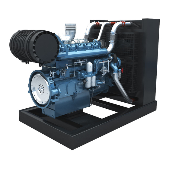
- Page 9 Safety Universal Warning The location of the Universal Warning label is illustrated below. 6M33 Gas Engine Series Figure 1.2B- 6M33 Gas Engine Illustration Do not operate or perform maintenance on this engine unless you have read and understand the instructions and warnings in this Operation and Maintenance Manual.
-
Page 10: Personal Safety
To ensure compliance with environmental protection laws, consult your local authorities who will advise you. Obey all local regulations for the handling and disposal of liquids. The products and spare parts supplied by Baudouin do not contain asbestos. -
Page 11: Fluid Safety
Safety 1.5 Fluid Safety All oil, natural gas, and some coolant liquids are flammable. If these liquids and gas are leaking onto hot surfaces they can cause a fire which can cause injury and/or damage. Do not check for leaks using any body part. -
Page 12: Welding
Safety The battery cables must be fitted with a battery switch and fuse or circuit breaker to isolate the circuit. Sulphuric acid contained in batteries is toxic and corrosive; it can burn clothes and skin or even cause blindness in case of contact with the eyes. -
Page 13: Electrical Risks
Safety before welding (control cabinets, electrical cabinets etc.). Comply with all legal provisions in force before conducting welding work. Do not use open fires. Make sure that the work will not affect the on-board electrical and electronic equipment. -
Page 14: Lines, Tubes And Hoses
Safety Flexible connections for cooling Flexible circuit connections fuel Electrical control systems and electronic fuel injection Earth faults can cause corrosion in the pipes and engine or genset unit compo- nents. 1.9 Lines, Tubes and Hoses ... -
Page 15: Cleaning The Engine
Safety Slowly unscrew the coolant filler plug to release pressure. 1.11 Cleaning the Engine Use personal protective equipment when cleaning an engine. Regularly clean the engine surface to remove any greasy deposits that may be flammable. Do not wash an engine in operation or which has just stopped. -
Page 16: General Precautions For Operation
Safety 1.12 General Precautions for Operation 1.12.1 Before any operation or maintenance on any Baudouin product Wear personal protective equipment (PPE) where required. For maintenance, place a “Do Not Use” or similar sign on the starter switches. ... - Page 17 Safety 1.12.2 Starting the Engine For initial start-up of a new engine, or the first start after a service, make provisions to be able to stop the engine if a fault occurs. This can be done by shutting off the gas or air supply to the engine.
-
Page 18: Product
Product 2. Product 2.1 Rating Definitions Rating definitions Running conditions Annual running time is unlimited. Continuous rated power is allowed. Continuous power No overload ability. -
Page 19: Engine Model
Application code Displacement per cylinder (L) ×10 Baudouin series Cylinder quantity 2.2.2.1 Product Series Code Product series Code is comprised by cylinder quantity, product code for Baudouin (M) and displacement per cylinder. 2.2.2.2 Application Code Code Application Land Power Generation Land Power Generation for Telecom Variable speed models (Pump, Air pressure machinery…) - Page 20 Product 2.2.2.4 Speed Code 3000 1500 1800 1500 & 1800 Code Engine speed code is only used for genset application. 2.2.2.5 Emission Stage Code Emission Stage Code Non-road No emission certification U.S. EPA 40 CFR 60 JJJJ U.S. EPA Tier 1 India CPCB I U.S.
- Page 21 Product 2.2.3 Engine Plate Figure 2.2.2A-6 M33 Gas Engine Plate Position **** ***...
-
Page 22: Engine Overview
Product 2.3 Engine Overview 2.3.1 Schematic Diagrams of 6M33 Gas Engine Figure 2.3.1A – Right Side View Air intake filter Ignition coil Air intake manifold Air intake throttle valve Cooling fan Alternator belt Alternator Coolant pump inlet Lube oil filter Lube oil centrifugal filter Lube oil dipstick Lube oil filler cap... - Page 23 Product Figure 2.3.1B – Left Side View Crankcase breather Turbocharger Gas fuel mixer Coolant outlet pipe Air intake filter indicator Starter Lube oil draining plug Vibration damper Cooling fan belt...
-
Page 24: Cooling Circuit
Product 2.4 Cooling Circuit 6M33 series gas engine is equipped with one pressurized cooling circuit to cool: Cylinder block and cylinder head Turbocharger Engine oil through oil cooler The internal circuit is designed for self-degassing. To provide effective engine protection against freezing, chemical and galvanic corrosion, cavitation and depositing, it is IMPERATIVE to use the recommended coolant as defined in the 6.1 Coolant Recommendation. - Page 25 Product Figure 2.4 B - Overall layout of Cooling Circuit (Left Side) High temp. coolant from High temp. coolant collection High temp. coolant from thermostat to radiator pipe turbocharger Coolant from cylinder block to Coolant flowing through turbocharger turbocharger bearing housing...
-
Page 26: Lubrication System
Product 2.5 Lubrication System 6M33 Series gas engine is equipped with a lubrication system including one oil cooler. The gear driving oil pump is located at the low front of the engine. Most of engine parts are lubricated by pressurized oil. For the requirement of lube oil, see the part 6.2. -
Page 27: Gas Supply System
Product 2.6 Gas Supply System 2.6.1 Gas supply diagrams of 6M33 gas engine The gas source should meet the standard of Chapter 6.3 Fuel Recommendation. The gas (50-100KPa) flows through gas filter, pressure reducer and shut-off valve in turn. Natural gas is mixed in certain proportion with air by the mixer that is controlled by ECU (Engine Control Unit). - Page 28 Product 2.6.2 Main Parts of Gas supply system Pressure Reducer Function: Reduce and regulate the compressed gas pressure to required range. Technical parameters: Inlet pressure: 0.5 bar; Outlet pressure: 30mbar~70mbar; Working temperature: -15℃~60℃. Figure2.6.2 A - Pressure Reducer ...
-
Page 29: Electronic Control Unit (Ecu) And Electronic Parts Introduction
Product 2.7 Electronic Control Unit (ECU) and Electronic Parts Introduction Function: ECU monitors inlet manifold pressure (MAP), inlet manifold temperature (MAT), engine speed, coolant temperature and exhaust oxygen concentration to control the action of electrical throttle valve, ignition timing and ignition orders after calculation. - Page 30 Product Camshaft signal sensor Function: Get revolution position of camshaft. Technical parameters: Working temperature: 40℃~150℃; Working voltage:(5±0.25)V; Magnetic field allowable: ≤2kA/m; Figure2.7.3-Camshaft signal sensor Coolant temperature sensor Function: Measure coolant temperature. Technical parameters: Rated working voltage: (5±0.15)V; ...
- Page 31 Product Engine speed sensor (optional) Function: Engine speed sensor is mainly used to measure engine‟s revolution speed. We can use it to compare with engine‟s revolution speed of camshaft signal sensor. Technical parameters: Magnetic field allowable: ≤2KA/m; Figure2.7.6-Speed sensor ...
- Page 32 Product Ignition coil Function: This system adopts independent cylinder ignition coil. ECU controls coil‟s charging time. Figure2.7.8-Ignition coil Ignition cable Function: Ignition cable is used to transmit high pressure spot generated by ignition coil to sparking plug so as to generate electric spark for igniting gas air mixture.
-
Page 33: Installation
Avoid installation related problem and damage. It is essential when installing and operating gas engines to comply with the local authority. S. I. Moteurs Baudouin is only liable for quality defects when the instruction has been fully observed. Failure to comply with the installation and operation instructions defined by Baudouin will void the warranty. -
Page 34: Engine Lifting
Installation 3.1 Engine Lifting 3.1.1 Lifting device Always use the lifting device to lift the very heavy parts that is unsuitable for carrying by hand. Check the lifting device status regularly such as hook and chain. Do not use unsafe tools. Do not use the tools before you are familiar with it. 3.1.2 Lifting the engine The 6M33 gas engine's net weight is approx.2110Kg. - Page 35 Installation The two lifting eyes of 6M33 series gas engine are illustrated as following: Figure 3.1.3 - Lifting eyes Rear lifting eye Front lifting eye...
-
Page 36: Engine Mounting
Installation 3.2 Engine Mounting In order to ensure the installation durability, pay attention on the following criteria: All the engine's mounting brackets should be used Vibration absorber should be arranged to reduce vibration from the engine to its chassis. The mounting brackets of 6M33 series gas engine are illustrated as following: Figure 3.2 - Engine brackets Right rear bracket... -
Page 37: Accessories
Installation 3.3 Accessories In order to ensure engine durability and performance, the accessory installation must meet the following items: During installation, add proper O-ring sealing in the cooling system pipes. As figure 3.3, the O-ring should be arranged flange before connecting pipe with coolant pump inlet. -
Page 38: Air Intake System
Installation 3.4 Air Intake System If the gas engine is without the air filter, operator should fit the air filters and filter status indicator. The air intake system must avoid entry of following materials: Water or rain. Dust. ... -
Page 39: Cooling System
Installation 3.6 Cooling System In order to ensure excellent engine life and cooling performance, the installation of the radiator must meet the following criteria: When installing the radiator, install the vibration absorber. Figure 3.6 - Vibration absorber arrangement If the engine works in a soundproof box, sealing rubber should be installed around the radiator to prevent the hot air beyond the engine from flowing back into the cool air entrance. -
Page 40: Gas Supply System
Installation 3.8 Gas Supply System The installation of the gas supplying system must comply with the following requirements: The typical gas supplying system arranged as : Gas source Gas filter Gas pressure regulator Engine intake pipe Gas/air mixer Gas shut off valve ... -
Page 41: Engine Electronic System
Installation 3.9 Engine Electronic System 3.9.1 Starter Circuit Wire size of starter main cable: ≥70mm Wire size of ground wire: ≥70mm Wire size of starter controlling cable: ≥ 1.5mm The wiring terminals of starter shall be equipped with protective caps;... -
Page 42: Engine Electronic Controlling System
Installation 3.10 Engine Electronic Controlling System 3.10.1 Harness overview Engine harness is used to connect various sensors (camshaft sensor, temp. sensor, etc.) and actuators (ignition coil, throttle, etc.) on the engine. Engine harness has been installed on the engine before selling, and integration interface is reserved for customer connection to controller harness. - Page 43 Installation "idle to rated switch" wire Pin No.: 27(signal) ,32 (ground). Install a switch with the two wires. Functional description: When the switch is on, the speed rises to the rated speed. When the switch is off, the speed decreases to idle speed.
- Page 44 Installation lower speed Pin No.: 14(signal), 32(signal ground). Install a switch with the two wires. Functional description: When the speed down switch is closed, the engine will reduce the speed at the default speed of 5 rpm/s based on the existing speed; when the two pin connection is disconnected, the engine will remain the final speed.
-
Page 45: Gen Set Installation Recommendation
Installation 3.11 Gen Set Installation Recommendation Installer must choose the proper location in order to avoid noise pollution. If the location is not proper, enclosure has to be used for noise reduction. Also, the proper exhaust silencer must be used if necessary. ... -
Page 46: Operation
Operation 4. Operation The first engine commissioning process should be handled by S. I. Moteurs Baudouin ap- proved personnel. The successful completion of this process, along with the checks and adjustments required by S. I. Moteurs Baudouin, will ensure that the engine runs efficiently, reliably, and safely. -
Page 47: Preparations Before Start
Operation 4.1 Preparations before Start Adding of engine oil Open the oil filler cap and add the engine oil. Using the dipstick to check the oil level. Figure 4.1A-Adding of engine oil Natural Gas Adding of the natural gas ... - Page 48 Operation Note! After installing the genset, make sure removing all adjustment bolts illustrated in fig. 4.1D before starting the genset. Figure 4.1D – Removing adjustment bolts after installing...
-
Page 49: Starting Up
Operation 4.2 Starting Up The following starting/stopping procedure is a simple example (not binding) and it‟s based on a simple starting control panel equipped with starting key. Please refer to the genset and/or genset control panel use & maintenance manual for the starting operation mode. ... -
Page 50: Operation Of The Powerkit Engine
Operation 4.3 Operation of the PowerKit Engine After the start of engine, idle the engine for 3minutes, and then increase the speed to 1000r/min to 1200r/min with some load. Only when the coolant temperature is above 60º C and the oil temperature is above 51º C, can the engine run with full load. The load and speed should be increased gradually. -
Page 51: Precautions For Running In Cold Environments
Operation 4.4 Precautions for running in cold environments Lubricating oil: Choose lubricating oil of different viscosities depending on the seasons. Coolant: Add antifreeze additive into the cooling system and choose the coolant of differ- ent grades depending on the ambient temperature. ... -
Page 52: Stopping The Powerkit Engine
Operation 4.5 Stopping the PowerKit Engine Avoid shutting down the engine at full load. Before the shut-down, engine load and should be reduced, and the engine should operate at low-load condition for 3 to 5 minutes. This allows the piston, cylinder head, liner, bushing and turbocharger to cool down, avoiding cylinder and bearing damage. -
Page 53: Electronic Control System
Operation 4.6 Electronic control system Reading the fault code via the diagnostic switch: Press the diagnostic switch (diagnostic lamp comes on), and then release to reset the diagnostic switch (diagnostic lamp turns off) The diagnostic lamp flashes and reports the fault code ... -
Page 54: Maintenance
Maintenance 5. Maintenance 5.1 General Safety Conditions for Maintenance SAFETY WARNING Users should carefully read the safety instructions before installation and operation of the engine. Safety conditions for preventive and corrective maintenance operations are intended to check. Engine and generator alignment. ... -
Page 55: Maintenance Table
Maintenance 5.2 Maintenance Table MOTEURS BAUDOUIN • Check = In operation hours or period, every. о Adjust = Hours and Months: A first-come-prevail. Δ Clean = □ Replace = Hour 1500 2250 3000 6000 OPERATION Month • The coolant level •... - Page 56 Maintenance MOTEURS BAUDOUIN • Check = In operation hours or period, every. о Adjust = Hours and Months: A first-come-prevail. Δ Clean = □ Replace = Hour 1500 2250 3000 6000 OPERATION Month □ Engine oil □ Oil filters Δ/□...
- Page 57 Maintenance MOTEURS BAUDOUIN • Check = In operation hours or period, every. о Adjust = Hours and Months: A first-come-prevail. Δ Clean = □ Replace = Hour 1500 2250 3000 6000 OPERATION Month Battery, battery electrolyte level, • battery charger, battery cables Tightness of hoses and hose •...
- Page 58 Maintenance MOTEURS BAUDOUIN • Check = In operation hours or period, every. о Adjust = Hours and Months: A first-come-prevail. Δ Clean = □ Replace = Hour 1500 2250 3000 6000 OPERATION Month • Coolant pump • Gas shutoff valve •...
-
Page 59: Maintenance Operations
Maintenance 5.3 Maintenance Operations 5.3.1 Maintenance Operations Check the coolant level Inspection window Check the level by eyes. Coolant level sensor Check the level on control panel. Level gauge. Check the level by eyes. CAUTION If coolant is not enough, shut off engine and after engine has cooled, add coolant through radiator filler cap. - Page 60 Maintenance Check the gas Check gas pressure and leakages. If the gas is not enough, add gas meeting the standards. CAUTION: Never bring flames near gas tank because it is highly flammable and dangerous. Open hood. ...
- Page 61 Maintenance Check the belt The belt is automatically tensioned with a tensioner. Inspect the alternator belt and the fan drive belts for wear and for cracking. Replace the belts if the belts are not in good condition as shown A and B.
- Page 62 Maintenance Check the air cleaner service indicator (if equipped). Check the maximum intake resistance only when the gas engine is running under full load. When the intake resistance reaches the maximum permissible limit, clean or replaces the filter element as per the manufacturer‟s instructions.
- Page 63 Maintenance Replace the gas filter Remove oil filters by hand. Clean filter seat. Clean the air filter, replace if needed Use 0.5MPa (73psi) clean air blow and sweep the dust on external filter element from inside to the outside, and DO NOT wash the filter element with oil or water.
- Page 64 Maintenance Clean the oil-gas separator element Check whether the drain valve is clear; clean it up if it is blocked or dirty. Replace oil cartridges (to be done with EVERY oil replacing) Remove oil filters by special tool. ...
- Page 65 Maintenance Clean the intercooler Use proper tools to remove foreign matter, like insect, leaves, etc. Use compressed air to clean dust. Clean the radiator and cooling system Clean the oil cooler Use steam to clean the oil cooler core.
- Page 66 Maintenance Check state and tightness of starter Check state and tightness of alternator Replace the spark plug Spark plug clearance adjustment method: If the clearance is wide, insert a feeler into the clearance, and tap the corner of the side electrode gently with a small wrench;...
- Page 67 Maintenance Check tightness of hoses and hose clamps Check conditions and tightness of electrical connectors Test operation of safety devices and alarm Replace the ignition coil Use multi-meter to check the contact situation of wiring harness and connectors.
- Page 68 Maintenance 5.3.2 Overhaul Operations 5.3.2.1 Overhaul Information An overhaul is replacing the major worn components of the engine. An overhaul is a maintenance interval that is planned. The engine is rebuilt with certain rebuilt parts or new parts that replace the worn parts. An overhaul also includes the following maintenance: ...
- Page 69 Maintenance Rebuild Replace Turbocharger Cylinder head assemblies Coolant pump Starter Replace Valve bridge Ignition cable assembly Rocker arm The fan bracket Rocker arm shaft Belt tensioner Unexpected problems may be found during a top overhaul. Plan to correct these problems, if necessary.
- Page 70 Maintenance The recommendations of parts for in-structure overhaul is as followed: Clean The lubricating pipes (rocker arm, Gas Mixer turbochargers) Clean Inspect Test Intercooler Oil cooler Gas reducer Throttle Throttle valve Shut off valve Inspect Replace ...
- Page 71 Maintenance order to completely rebuild the engine. In some cases, the engine is relocated for disassembly. For the major overhaul, all of the bearings, seals, gaskets, and components that wear are disassembled. The parts are cleaned and the parts are inspected. If necessary, the parts are replaced.
- Page 72 Do not attempt to clean the turbine wheel. For information regarding removal and installation, see the repair manual or consult your Baudouin dealer. For information about repair of the turbocharger or about replacement of the turbocharger, consult your Baudouin dealer.
- Page 73 Inspect the pre lube pump for the following conditions: Cracks Pin holes Proper operation Wear Inspect the pre lube pump for leaks. Replace all of the seals if a leak is observed. If repair or replacement is necessary, consult your Baudouin dealer for assistance.
- Page 74 Corrosion Wires that are worn or frayed Cleanliness Rebuild the starter if necessary. Consult your Baudouin dealer for assistance on the removal and installation of the starter. Intercooler Inspect Check if there is any deformation ...
- Page 75 Install the core. For more information on cleaning the cores, consult your Baudouin dealer. Test Check any leakage at test: make sure there is no any leakage in one minute when the oil duct in pressure of (1.0-1.2) Mpa, water duct in pressure of (0.4-0.5) Mpa.
-
Page 76: Storage Protection Instruction
Maintenance 5.4 Storage Protection Instruction 5.4.1 Necessity of Anti-rust Protection If your engine is out of operation and using for a period of time, then precautions should be taken to protect your engine from damage and to ensure proper operation when you re-operate the engine. - Page 77 Maintenance Up to three months Each week operate the engine until the normal temperature of operation is reached. If the engine doesn't have the start conditions, for example, doesn‟t have the start equipment, etc., turn the crankshaft by hand, in the normal direction of rotation (anti-clockwise as seen on the flywheel), a minimum of three revolutions.
- Page 78 Maintenance Waxed paper Wax paper is a surface-coated wax that has excellent water and oil resistance. Wrap parts and sealing to prevent rust. Adhesive tape Use a sealing tape with appropriate adhesive properties. DO NOT use duct tape because duct tape gets loosen over time.
- Page 79 Maintenance Raw Water Systems Completely drain the raw water system by removing all the drain plugs from the raw water pump, water shield manifolds, heat exchanger bonnets, and aftercooler. After the system has been drained, inspect all zinc plugs (normally painted red) for corrosion damage. Note! To ensure complete drainage and evaporation during storage, DO NOT install the drain plugs and zinc plugs.
- Page 80 Maintenance 1000 cu in) of engine displacement. Electrical system Battery If battery is provided for engine starting, it should be disconnected and stored in a cool, dry place after ensuring electrolyte level (refill with distilled water if necessary). It is recommended to recharge the battery once in a month.
- Page 81 Maintenance not need to do this operation). Check the battery level. Check the condition of the fan and alternator belts. Replace the belts, if necessary. Tighten the belts as specified in the Operation & Maintenance Manual. Check the engine harness if the harness is not aging. Replace the harness, if necessary. ...
-
Page 82: Appendix
(chemical and galvanic). It improves also boiling temperature, resistance to rust and avoids scale deposit formation. The coolant used in Baudouin engines should meet the ASTM D6210 standard, and the coolant used in Baudouin engines should not contain 2-ethylhexanoate, which has compatibility problems with silicone rubber. -
Page 83: Lubricant Oil Recommendation
That can produce fewer deposits on the valves and pistons and extend the service life of the engine. For the engines of new installation or the use of new types of oils, Baudouin recommends take oil samples frequently from the engines for analysis to make sure the engine can be protected completely, and make records of the analysis results to evaluate the quality of the oils and determine the oil changes. - Page 84 Appendix Viscosity and temperature properties specification High-temperature and Low-temperature Viscosity (100℃) high-shear viscosity Pour point/℃ ≤ Project kinematic viscosity (150℃, 10 ) /mm² /s /mPa· s(℃)≤ /mPa· s ≥ Test method CECL-36-T-84 ASTM D-445 ASTM D4741-87 ASTM D5293 ASTM D 97 /ISO 3104 ASTM D 4582-95 ASTM D4624-93...
-
Page 85: Gas Recommendation
Appendix 6.3 Gas Recommendation > Natural Gas: Pipeline natural gas with a heating value of 36MJ/m³ (or above.),CH 80%. Gas quality requirements (measure within 1 meter of engine gas inlet): Intake pressure is (3~5) kPa (after the pressure regulator), customers can choose their own regulator. -
Page 86: Baudouin Special Tools
Appendix 6.4 Baudouin Special Tools Name 3D Model Piston installing guider Crankshaft rotating tool Rear oil seal installer Front oil seal installer... - Page 87 Appendix Name 3D Model Flywheel brake Cylinder liner installer Flywheel hanger tool Camshaft mounting tool (aluminum) Valve collet assembling tool...
- Page 88 Appendix Name 3D Model Cylinder block expansion tool Shock absorber guider Piston extraction tool The 21# socket tools Camshaft bush installer...
-
Page 89: Common Faults And Troubleshooting
Appendix 6.5 Common Faults and Troubleshooting 6.5.1 Troubleshooting Engine faults and analysis Common Faults Possible Causes Fault Inspection and Treatment Check whether gas is enough or not. 1. Gas supply problem Check whether gas supply valve is open or not. Check the gas pipeline for gas leak. - Page 90 Appendix Check the air intake 1. There is air leak in the air intake pipeline pipeline for leak 2. The spark plug or ignition system has Check the spark plug and 2. The idle speed failure. high-voltage cable. is unstable 3.
- Page 91 Appendix Check the ignition advance 6. Abnormal ignition advance angle. angle and the clearance between phase sensors. 4. The engine is Check the valve clearance 7. The clearance of intake and exhaust under-powered according to the operation valves is adjusted improperly. manual for engine.
- Page 92 Appendix 6.5.2 Diagnostic Fault Codes List DTC : Waste Gate Valve Open or Short Grnd 1188 DTC: Boost pressure Higher than Expected 1692 DTC: Boost pressure Lower than Expected 1692 DTC: Over boost 1692 DTC: UEGO INRC Open Fault 520555 DTC: UEGO INRC Short to GND Fault 520555 DTC: UEGO INRC Short to Batt Fault...
- Page 93 Appendix DTC: Spark 2 Open Primary 1269 DTC: Spark 2 Max Current 1269 DTC: Spark 3 Open Primary 1270 DTC: Spark 3 Max Current 1270 DTC: Spark 4 Open Primary 1271 DTC: Spark 4 Max Current 1271 DTC: Spark 5 Open Primary 1272 DTC: Spark 5 Max Current 1272...
- Page 94 Appendix DTC: PostCat O2 Failed on Rich Side 3227 DTC: PostCat O2 Heater Short Open Fault 3227 DTC: PreCat O2 inactive fault 3217 DTC: PreCat O2 Failed on Lean Side 3217 DTC: PreCat O2 Failed on Rich Side 3217 DTC: PreCat O2 input high 3217 DTC: PreCat O2 input Low 3217...
- Page 95 Appendix DTC: EFR Position Voltage High 1442 DTC: EFR Position Voltage Low 1442 DTC: EFR Status 1442 DTC: EFR Drive fault 1442 DTC: EFR adapt low fault 1442 DTC: EFR adapt high fault 1442 DTC: CAN Line Circuit/Bus Error Passive DTC: CAN Tx_Rx Warning DTC: CAN Line Circuit/Bus Error Passive 520707...
- Page 96 Appendix DTC: Knock Sensor Open Circuit DTC: Knock Sensor short Circuit DTC: Knock 2 Sensor Open Circuit 516098 DTC: Knock 2 Sensor short Circuit 516098 DTC: delta Pressure - Voltage High 1391 DTC: delta Pressure - Voltage Low 1391 DTC: FuelShutOffStuckOpen DTC: Low Fuel Pressure DTC: deltaP Higher Than Expected 1391...
-
Page 97: Maintenance Log
Appendix 6.6 Maintenance Log Current Frequency Preventive Overhaul Note Maintenance Operating Hours Hours Visa or Date / Period / Period stamp... - Page 98 Appendix Current Frequency Preventive Overhaul Note Maintenance Operating Hours Hours Visa or Date / Period / Period stamp...
- Page 99 Appendix Current Frequency Preventive Overhaul Note Maintenance Operating Hours Hours Visa or Date / Period / Period stamp...
-
Page 100: Index
Appendix Index A Air Intake System ............................ 39 Appendix ..............................83 C Charging Circuit ............................42 Common Faults and Troubleshooting ..................... 90 Coolant Recommendation ........................83 Coolant Safety............................14 Cooling Circuits ............................24 Cooling System ............................40 D Diagnostic Fault Codes List ........................93 E... - Page 101 M Maintenance ............................55 Maintenance Log ............................ 98 Maintenance Operations ........................60 Maintenance Table ..........................56 O Operation..............................47 Operation of the PowerKit Engine ......................51 P Personal Safety ............................10 Precautions for running in cold environments ..................52 Preparations before Start ........................48 R...
- Page 102 Appendix Contact Us Address: Moteurs Baudouin, Technoparc du Bregadan, 13260 Cassis, France Website: Baudouin.com Aftersales Service Center: sav@baudouin.com ©2018 Société International des Moteurs Baudouin All Rights Reserved...