Advertisement
INCLUDED IN BOX
- 1 x Owner's Manual
- 1 x Pair of Test Leads
- 1 x Storage Bag
- 1 x AstroAl 2000 Counts CLAMP METER
DIMENSIONS

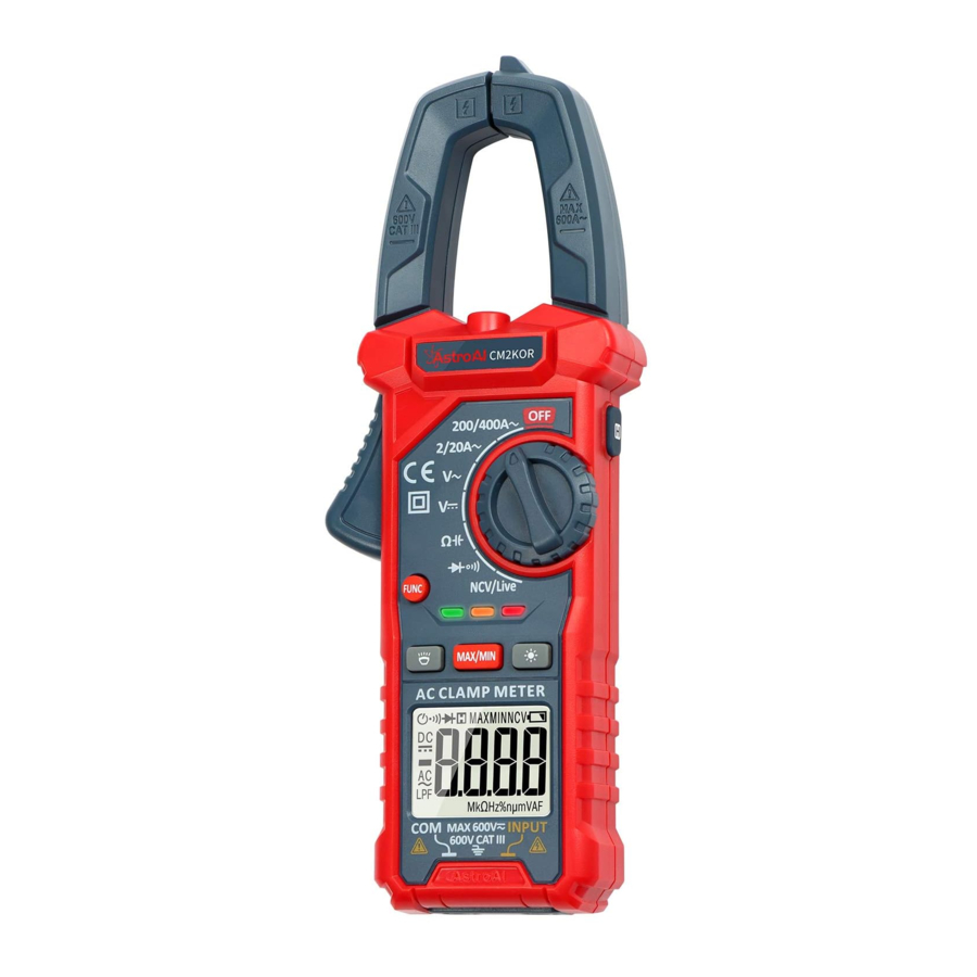
DIAGRAM

- NCV Detector
- Transformer Jaws
- Rotary Switch
- Backlight Button
- MAXIMIN Button
- Flashlight Button
- FUNC Button
- Trigger
- Display
- Flashlight
- DATA HOLD Button
- Indicator Light
- Test Leads
- Storage Bag
- COM Terminal
- INPUT Terminal
GETTING TO KNOW YOUR DEVICE
BUTTON FUNCTIONS
 |
 NOTE: Pay special attention to the selected setting before performing any tests. NOTE: Pay special attention to the selected setting before performing any tests. |
 |
|
 |
|
 |
|
 |
|
| INPUT Jack |
|
| COM Jack |
|
BATTERY REPLACEMENT
- If the low battery sign appears on the LCD display, the battery should be replaced. Remove the screws and open the back case, replace the expended battery with fresh batteries. (Size AAA, 1.5V x2).
![warning]() NOTE: Replace batteries immediately to prevent inaccurate readings due to low power. This also prevents potential safety hazards.
NOTE: Replace batteries immediately to prevent inaccurate readings due to low power. This also prevents potential safety hazards.
AUTO POWER OFF
- If the meter is not in operation for 15 minutes, it will turn off automatically. To turn it on again, simply rotate the range switch or press any button.
HOW TO USE THIS MULTIMETER
The meter is very sensitive. It will be affected by nearby magnetic fields. Without touching any objects, there may be a reading jumping on the screen when it is turned on. This is a normal occurrence for a digital meter and it does not affect the measurement results.
NOTE
- To avoid damage to the Meter, do not measure voltage exceeding 600V.
- Pay special attention to safety when measuring high voltage to avoid electric shock or personal injury.
- Before using the Meter to test a known voltage or current, confirm that the Meter functions work properly.
MEASURING AC CURRENT
- Turn the rotary dial to the "
![]() " or "
" or "![]() " setting. The screen will display "
" setting. The screen will display "![]() " indicating that the measurement function is AC current.
" indicating that the measurement function is AC current.

 " or "
 " setting. The screen will display "
 " indicating that the measurement function is AC current.
- Press the trigger to open the transformer jaws, clamp the conductor to be tested, and then slowly release the trigger until the clamp head is completely closed.
Determine whether the conductor to be tested is clamped in the center of the clamp head. Additional errors will occur if the conductor is not placed in the center of the clamp head.
![]()

- After the reading stabilizes, record it from the LCD screen.
- Turn the rotary switch to the OFF position to turn off the Meter.
MEASURING AC/DC VOLTAGE
- Insert the red test lead into the INPUT terminal and the black test lead into the COM terminal
- Turn the rotary dial to the continuity test, touch the red test lead and the black test need to check whether they are normal The buzzer will beep and the indicator light will come on if the test leads are normal.
![]()

- Turn the rotary dial to the "V~" setting. The screen will display "
![]() " indicating that the measurement function is AC voltage.
" indicating that the measurement function is AC voltage.

- Turn the rotary dial to the "
![]() " setting. The screen will display "
" setting. The screen will display "![]() " indicating that the measurement function is DC voltage.
" indicating that the measurement function is DC voltage.

- Connect the meter in parallel to the circuit under test.
![warning]() NOTE: If the reading is negative when measuring the DC voltage, it means that the positive and negative poles of the test leads are reversed, please change the test leads.
NOTE: If the reading is negative when measuring the DC voltage, it means that the positive and negative poles of the test leads are reversed, please change the test leads.
 " indicating that the measurement function is AC voltage.
 " setting. The screen will display "
 " indicating that the measurement function is DC voltage.
- After the reading stabilizes, record the reading from the LCD screen
- Turn the rotary switch to the OFF position to turn off the Meter.
VOLTAGE NOTES
- To avoid damage to the meter, do not measure voltage exceeding 600V DC or 600V AC CATIII.
- If the AC setting is used to measure DC and vice versa, an overflow symbol will be displayed. Performing this has the potential to damage the Meter or any components you are attempting to test.
- When measuring voltage, the result will fluctuate depending on the power supply. Generally speaking, the result will fluctuate ±10V, which is NOT an inaccurate result.
MEASURING RESISTANCE
- Insert the red test lead into the INPUT terminal and the black test lead into the COM terminal
- Turn the rotary dial to the continuity test, touch the red test lead and the black test lead to check whether they are normal The buzzer will beep and the indicator light will be on if the test leads are normal.
![]()
- Turn the rotary dial to the "
![]() " setting. The screen will display "Ω" indicating that the measurement function is resistance.
" setting. The screen will display "Ω" indicating that the measurement function is resistance.


 " setting. The screen will display "Ω" indicating that the measurement function is resistance.
- Connect the test leads to both ends of the circuit or resistor under test (connect the leads to the resistance under test in parallel)
- After the reading stabilizes, record the reading from the LCD screen
- Turn the rotary switch to the OFF position to turn off the Meter.
RESISTANCE NOTES
- Do not change the resistance while taking a measurement. Doing so may damage the Meter and affect the test results.
- Do not test parallel circuits. The accuracy of the measurement will be affected, and the results may not be accurate.
- Do not directly measure the internal resistance of micrometers, galvanometers, batteries, and other instruments
MEASURING CAPACITANCE
- Insert the red test lead into the INPUT terminal and the black test lead into the COM terminal.
- Turn the rotary dial to the continuity test, touch the red test lead and the black test lead to check whether they are normal. The buzzer will beep and the indicator light will be on if the test leads are normal.
![]()

- Turn the rotary dial to the "
![]() " setting. Press the FUNC button to switch to capacitance test.
" setting. Press the FUNC button to switch to capacitance test.
The screen will display "n F" indicating that the measurement function is capacitance.

- Connect the test leads to both ends of the circuit or resistor under test (connect the leads to the resistance under test in parallel)
- After the reading stabilizes, record the reading from the LCD screen
- Turn the rotary switch to the OFF position to turn off the Meter.
 " setting. Press the FUNC button to switch to capacitance test.
 CAPACITANCE TIPS
- If the measured value is significantly different from the value marked on the capacitor, the capacitor is damaged
CAPACITANCE NOTES
- Before measuring the capacitor, discharge it to avoid damage to the Meter. Do so by connecting the capacitor to a high-powered resistor.
- Discharge the capacitor after measurement to avoid any potential safety hazards
- If the capacitance is large, it may take a long time for the reading to stabilize.
CONTINUITY TEST
- Insert the red test lead into the INPUT terminal and the black test lead into the COM terminal.
- Turn the rotary dial to the "
![]() " setting. The screen will display "
" setting. The screen will display "![]() " indicating that the measurement function is continuity. Touch the red test lead and the black test lead to check whether they are normal. The buzzer will beep if the test leads are normal.
" indicating that the measurement function is continuity. Touch the red test lead and the black test lead to check whether they are normal. The buzzer will beep if the test leads are normal.
![]()
- Connect the test leads to both ends of the circuit or resistor under test (parallel). If the resistance of the circuit or resistor under test is connected and less than 50Ω, the buzzer will emit a beep and the measured resistance value will be displayed on the LCD display.
![]()
- If the circuit or resistor under test is disconnected, or the resistance value is greater than 50Ω, the LCD screen will display "OL".
![]()
- Turn the rotary switch to the OFF position to turn off the Meter.
 " setting. The screen will display "
 " indicating that the measurement function is continuity. Touch the red test lead and the black test lead to check whether they are normal. The buzzer will beep if the test leads are normal.


DIODE TEST
- Insert the red test lead into the INPUT terminal and the black test lead into the COM terminal.
- Turn the rotary dial to the continuity test, touch the red test lead and the black test lead to check whether they are normal. The buzzer will beep and the indicator light will come on if the test leads are normal.
![]()

- Turn the rotary dial to the "
![]() " setting. Press the FUNC button to switch to the diode test. The screen will display "
" setting. Press the FUNC button to switch to the diode test. The screen will display "![]() " indicating that the measurement function is diode.
" indicating that the measurement function is diode.

- Connect the red test lead to the anode of the diode under test and the black test lead to the cathode of the diode
![warning]() NOTE: Usually the anode of the diode is the longer end.
NOTE: Usually the anode of the diode is the longer end.
- The LCD screen will display the approximate voltage drop reading of the diode. If the test leads are connected reversely, "OL" will be displayed on the LCD screen. Please replace the test leads to measure again.
- Turn the rotary switch to the OFF position to turn off the Meter.
 " setting. Press the FUNC button to switch to the diode test. The screen will display "
 " indicating that the measurement function is diode.
DIODE TEST TIPS
- Is the diode functioning correctly? If the red test lead is connected to the positive pole of the diode and the black lead is connected to negative, then the diode should be in a forward conduction state, and the displayed value is the forward voltage drop.
- Normal diode forward pressure drops: the general silicon tube is 0.5-0.7 V, germanium tube is 0.15-0.3V.
- If "0000" is displayed, the diode is broken.
- You can also verify that the red test lead is connected to the negative pole of the tested diode and the black test rod is connected to the positive pole. The diode should display "OL".
POLARITY JUDGMENT METHOD
- Switch the Multimeter to the Resistance setting.
- Connect the two test leads to the two electrodes of the diode.
- Measure one result, then swap the positions of the test leads, then measure the second result.
- The larger result is the reverse resistance and the smaller result is the forward resistance. The smaller resistance is when the black test lead is connected to the positive end of the diode and the red lead is connected to the negative end.
NON-CONTACT VOLTAGE
- Turn the rotary dial to the "NCV/Live" setting. The screen will display "NCV" indicating that the measurement function is noncontact voltage.

- Move the NCV detector close to the point to be tested: When the Meter senses a weak AC signal, the green indicator light will be on, the buzzer will emit a slow, audible beep and the screen will display "---L"; When the Meter senses a strong AC signal, the red indicator light will be on, the buzzer will emit a quick beep and the screen will display "---H".
![warning]() NOTE: When the indicator light is on, it means there is voltage, please pay attention to your safety!
NOTE: When the indicator light is on, it means there is voltage, please pay attention to your safety!
- Turn the rotary switch to the OFF position to turn off the Meter.

LIVE WIRE DETECTION
- Insert the red test lead into the INPUT terminal
- Turn the rotary dial to the "NCV/Live" setting. Press the "FUNC" button to switch to live wire detection. The screen will show "Live" indicating that the measurement function is live wire detection.
![]()
- Touch the point to be measured with the tip of the red test lead: When the indicator light is on, it means that the measured position is live wire, please pay attention to your safety! The reason that the green light is on may be that the test lead is not fully connected to the socket. Please test again after the test lead is fully connected.
![warning]() NOTE: When the meter senses a weak AC signal, the LCD screen will display "---L", and the buzzer will emit a slow beep; When the meter senses a strong AC signal, the LCD screen will display "---H", and the buzzer will emit a quick beep.
NOTE: When the meter senses a weak AC signal, the LCD screen will display "---L", and the buzzer will emit a slow beep; When the meter senses a strong AC signal, the LCD screen will display "---H", and the buzzer will emit a quick beep.
- Turn the rotary switch to the OFF position to turn off the Meter.

MAINTENANCE
CLEANING THE METER
If there is dust or humidity in the terminals, it may produce erroneous measurements.
Please clean the Meter as follows:
- Turn off the power to the Meter and remove the test leads.
- Turn the meter over and shake out the dust accumulated in the input jack, wipe the case with a damp cloth or mild detergent. Wipe the contacts in each terminal with a clean cotton swab dampened in alcohol.
SPECIFICATIONS
| Digital Display | 2000, 3½ |
| Sampling Speed | 3 Times/Second |
| LCD Dimensions | 35X25mm |
| Range Selection | Auto or Manual |
| Polarity Indication | " " Automatically displayed " Automatically displayed |
| Overload Indication | "OL" Displayed |
| Low Battery Indication |  displayed when battery voltage is lower than normal displayed when battery voltage is lower than normal |
| Work Environment | 32ºF~104ºF (0ºC~40ºC; <80% RH, <10ºC Non-condensing) |
| Storage Temperature | 14ºF~122ºF (-10ºC~6ºC; <70% RH, Remove the Battery) |
| Power | 2 x 1.5V AAA Batteries |
| Weight | Approximately 203g |
| Dimensions | 195x68x29mm |
| Safety/Compliance | CAT.III 600V; Pollution Level: 2; Altitude <2000m. |
DETAILED SPECIFICATION
PRECISION INDEX
Reference Conditions: Ambient Temperature: 18ºC to 28ºC,
Relative Humidity: ≤80%; Accuracy: (% rdg + dgts)
The accuracy is applicable within one year after calibration.
DC VOLTAGE
| Range | Resolution | Accuracy |
| 2V | 0.001V | ±(0.5% rdg + 5 dgts) |
| 20V | 0.01V | |
| 200V | 0.01V | |
| 600V | 1V |
- Input Impedance: 10MΩ
- Overload Protection: 600V
- Maximum Measuring Voltage: 600V
AC VOLTAGE
| Range | Resolution | Accuracy |
| 2V | 0.001V | ±(1.0% rdg + 5 dgts) |
| 20V | 0.01V | |
| 200V | 0.1V | |
| 600V | 1V |
- Input Impedance: 10MΩ
- Overload Protection: 600V
- Maximum Measuring Voltage: 600V
- Frequency Range: 40Hz ~1kHz
- Response: True RMS
AC CURRENT
| Range | Resolution | Accuracy |
| 2A | 0.001A | 50~60Hz: Other: |
| 20A | 0.01A | |
| 200A | 0.1A | |
| 600A | 1A |
- Frequency Range: 40Hz~400Hz
- Response: True RMS
RESISTANCE
| Range | Resolution | Accuracy |
| 200Ω | 0.1Ω | ±(1.0% rdg + 5 dgts) |
| 2kΩ | 0.001kΩ | |
| 20kΩ | 0.01kΩ | |
| 200kΩ | 0.1kΩ | |
| 2MΩ | 0.001MΩ | |
| 20MΩ | 0.01MΩ |
- Overload Protection: 250 V
CAPACITANCE
| Range | Resolution | Accuracy |
| 2nF | 0.001nF | ±(4.0% rdg +5 dgts) |
| 20nF | 0.01lnF | |
| 200nF | 0.1nF | |
| 2μF | 0.0011μF | |
| 20wF | 0.01 μF | |
| 200μF | 0.1μF | |
| 2mF | 0.001mF |
- Overload Protection: 250 V
CONTINUITY
 | The buzzer inside the Meter will beep if the resistance <50Ω. | Open Circuit Voltage: approximately 1.0V; Overload Protection: 250V |
DIODE TEST
 | The approximate diode forward voltage value will be displayed | Reverse DC Voltage: approximately 2.0V; Overload Protection: 250V |
SAFETY INSTRUCTIONS

To avoid possible electric shocks or personal injury, and to avoid possible damage to the Meter or to the equipment being tested, adhere to the following rules:
- Use the Meter strictly in accordance with this manual, otherwise the protection function provided by the Meter may be damaged or weakened
- Please be especially careful when measuring over 60V DC, 30V AC RMS or 42V peak value as there is a danger of an electric shock.
- Do not apply more than the rated voltage, as marked on the Meter, between the terminals or between any terminal and grounding
- Check whether the Meter is working normally by measuring the known voltage, do not use it if the readings are incorrect or the Meter is damaged
- Use the Meter according to the measurement category, voltage or current rating specified on the meter or manual.
- Before using the meter, please check whether there are cracks or damage to the plastic parts of the meter casing. Do not use the Meter if all or part of the exterior casing is damaged.
- Before using the Meter, please check whether the test leads are cracked or damaged. Please replace the test leads with the same model and same electrical specifications if the leads are damaged.
- Comply with local and national safety regulations. Wear personal protective equipment (such as approved rubber gloves, masks, and flame-retardant clothing, etc.) to prevent injury from electric shocks and arcs when hazardous live conductors are exposed.
- Replace the battery as soon as the low-battery indicator appears to avoid measurement errors.
- Do not use the Meter around explosive gas or steam; or humid environments.
- When using the test leads, keep your fingers behind the finger guards.
- Do not measure the current when a test lead is inserted into the INPUT Terminal.
- Do not let the Meter work alone without someone being present.
- When measuring, connect the neutral wire or ground wire first, and then connect the live wire; when disconnecting, disconnect the live wire first, and then disconnect the neutral wire and the ground wire.
- Before opening the case or battery cover, remove the test leads from the Meter first. Do not use the Meter when it is disassembled or the battery cover is opened.
- The Meter can only be used with the equipped test leads to meet the requirements of safety standards. If the test leads are damaged and need to be replaced, replace only with the same model and the same electrical specifications.
ELECTRICAL SYMBOLS
 | AC (Alternating Current) |  | Resistance |
 | DC (Direct Current) |  | Continuity Test |
 | AC and DC |  | Diode Test |
 | Capacitance |  | Low Battery |
 | Current |  | Voltage |
| | Warning |  | Dangerous Voltage may be present |
 | Earth Ground |  | Non-Contact Voltage Setting |
Customer Support at support@astroai.com.

Documents / ResourcesDownload manual
Here you can download full pdf version of manual, it may contain additional safety instructions, warranty information, FCC rules, etc.
Download AstroAI CM2K0R - 2000 Counts Multimeter, Multi Clamp Meter Manual
Advertisement


Need help?
Do you have a question about the CM2K0R and is the answer not in the manual?
Questions and answers