
Summary of Contents for B&R Industries ACOPOSmotor Compact
- Page 1 ACOPOSmotor Compact User's manual Version: 1.00 (August 2023) Order no.: MAACPMOTC-ENG Translation of the original documentation...
- Page 2 Publishing information B&R Industrial Automation GmbH B&R Strasse 1 5142 Eggelsberg Austria Telephone: +43 7748 6586-0 Fax: +43 7748 6586-26 office@br-automation.com Disclaimer All information in this document is current as of its creation. The contents of this document are subject to change without notice.
-
Page 3: Table Of Contents
4.3.1 POWERLINK - LED status indicators..................... 29 4.3.2 RDY/ERR - LED status indicators......................29 4.3.3 Status changes when starting up the operating system loader.............. 30 4.4 Order data for ACOPOSmotor Compact modules..................31 4.5 Technical data...............................32 4.5.1 General information..........................32 4.5.2 Inverter module............................33... - Page 4 Table of contents 4.6.6 Permissible shaft load..........................38 4.7 8D1Bx - Technical data..........................39 4.7.1 Overview..............................39 4.7.2 8D1B22.eI - 4,500 rpm (8GM40, gearbox size 060) - Technical data............ 40 4.7.3 8D1B22.eI - 4,500 rpm (8GM45, gearbox size 067) - Technical data............ 42 4.7.4 8D1B22.eI - 4,500 rpm (8GM50, gearbox size 070) - Technical data............
- Page 5 Table of contents 4.9.12 8D1B3x.xxxEH - 8GM55 gearbox (gearbox size 080)................ 144 4.9.13 8D1B3x.xxxHJ - 8GG40 gearbox (gearbox size 090).................145 4.10 Pinouts...............................146 4.10.1 Hybrid cable - Pinout...........................146 4.10.2 Electronics option - Pinout........................147 4.11 POWERLINK node number setting......................147 5 Dimensioning......................148 5.1 Power supply...............................148 5.1.1 Power supply unit..........................
- Page 6 9.1.1.1 Requirements for immunity to interference..................193 9.1.1.2 Emission requirements........................195 9.1.1.3 Climate conditions..........................196 9.1.1.4 Electrical safety..........................196 9.1.2 UL / CSA - ACOPOSmotor Compact (8D1)..................197 9.1.3 UKCA..............................197 9.2 Standards and definitions for safety technology..................198 10 Disposal........................200 10.1 Safety................................ 200 10.1.1 Protective equipment...........................
-
Page 7: Introduction
Introduction 1 Introduction 1.1 Manual history Version Date Comment 1.00 October 2023 First edition Editorial corrections are not listed. 1.00... -
Page 8: General Safety Guidelines
General safety guidelines 2 General safety guidelines 2.1 Organization of notices Safety notices Contain only information that warns of dangerous functions or situations. Signal word Description Danger! Failure to observe these safety guidelines and notices will result in death, severe injury or substantial damage to property. Warning! Failure to observe these safety guidelines and notices can result in death, severe injury or substantial damage to property. -
Page 9: Qualified Personnel
General safety guidelines 2.3 Qualified personnel The use of safety-related products is restricted to the following persons: • Qualified personnel who are familiar with relevant safety concepts for automation technology as well as applicable standards and regulations. • Qualified personnel who plan, develop, install and commission safety equipment in machines and systems. Qualified personnel in the context of this manual's safety guidelines are those who, due to their training, experience and instruction combined with their knowledge of relevant standards, regulations, accident prevention guidelines and operating conditions, are qualified to carry out essential tasks and to recognize and avoid potentially dangerous... -
Page 10: Regulations For Proper Esd Handling
General safety guidelines 2.5.2 Regulations for proper ESD handling Electrical assemblies with housing • Do not touch the connector contacts of connected cables. • Do not touch the contact tips on circuit boards. Electrical assemblies without housing The following applies in addition to "Electrical assemblies with housing": •... -
Page 11: Operation
General safety guidelines 2.8 Operation 2.8.1 Protection against contact with electrical parts Danger! To operate drive systems, it is necessary for certain parts to carry dangerous voltage levels over 60 VDC. Touching one of these components can result in a life-threatening electric shock. There is a risk of death, serious injury or damage to property. -
Page 12: Protection Against Hazardous Movements
General safety guidelines 2.8.2 Protection against hazardous movements Danger! Improper control of motors can result in unintended hazardous movements! Such incorrect behavior can have various causes: • Incorrect installation or faults when handling components • Improper or incomplete wiring • Defective devices (drive system, motor, position encoder, cables, brake) •... -
Page 13: Cybersecurity Disclaimer For Products
General safety guidelines 2.10 Cybersecurity disclaimer for products B&R products communicate via a network interface and were developed for secure connection with internal and, if necessary, other networks such as the Internet. Information: In the following, B&R products are referred to as "product" and all types of networks (e.g. internal networks and the Internet) are referred to as "network". -
Page 14: System Characteristics
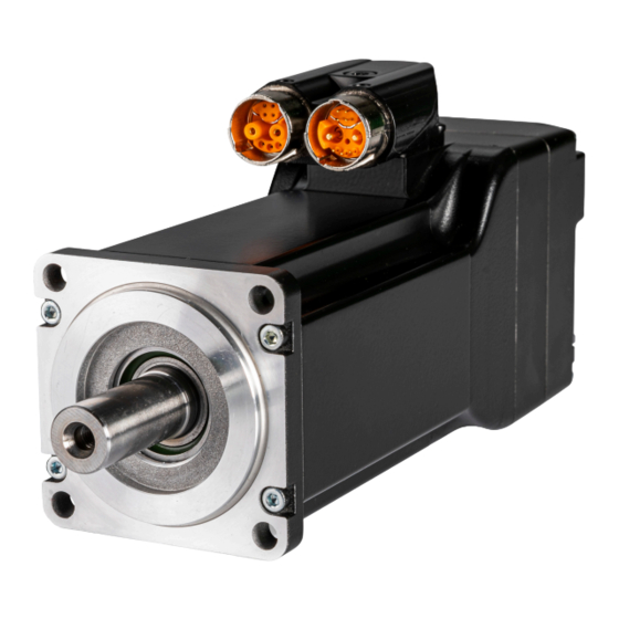
ACOPOSmotor Compact modules cover a power range of up to 0.35 kW and measure just 60 mm x 90 mm (w x h) in the smallest variant. Despite the compact dimensions, a fully-fledged servo drive is integrated that processes control loops with a cycle time of 50 μs. -
Page 15: Decentralized And Flexible
3.2 Decentralized and flexible In terms of topology, the ACOPOSmotor Compact module is wired either as a simple line structure or as a tree structure. Node number assignment takes place automatically in the line structure. If the address must still be set, however, this can be done without opening the housing. - Page 16 Topologies ACOPOSmotor Compact modules do not require an additional servo drive. ACOPOSmotor Compact modules do not require an additional servo drive and are simply integrated into the POW- ERLINK network. Power is supplied via an DC power supply unit. ACOPOSmotor Compact modules can be integrated into ACOPOSmulti architecture.
-
Page 17: Technical Data
Technical data 4 Technical data 4.1 8D1 order key Construction type A ... Without gearbox B ... Direct gearbox mounting C ... Gearbox flanged see "Construction type (b)" on page 19 Size Valid values: 2, 3 see "Size (c)" on page 19 Length Valid values: 2, 3 see "Length (d)"... - Page 18 Technical data Note: Order keys only provide information about possible combinations in exceptional cases. Information about possible combinations is available in the CAD configurator (cad.br-automation.com). 1.00...
-
Page 19: Construction Type (B)
4.1.3 Length (d) see "Order key" on page 17 ACOPOSmotor Compact modules are available in various lengths. These differ in the power data with identical flange dimensions. The different lengths are differentiated by a digit (d) in the order number. - Page 20 Technical data Lengths (d) 8D1xx3 8D1A3 8D1B3 8D1C3 1.00...
-
Page 21: Motor Encoder System / Electronics Option (E)
4.1.4 Motor encoder system / Electronics option (e) see "Order key" on page 17 ACOPOSmotor Compact modules are equipped with EnDat 2.2 encoders and optionally available with 2 external connections. The external connections are a combination of a 24 VDC output and trigger input. - Page 22 The keyways for ACOPOSmotor Compact modules conform to keyway form N1 per DIN 6885-1. Form A keyed The current value of the revolutions when the holding brake is applied can be read out under parameter ID BRAKE_WEARMON_REVO.
- Page 23 8D1A - Oil seal All ACOPOSmotor Compact modules without gearbox (8D1A) are available with an optional form A oil seal per DIN 3760. With an oil seal, the ACOPOSmotor Compact modules meet the requirements for IP65 protection per EN 60529.
-
Page 24: Gearbox (H)
Technical data 4.1.7 Gearbox (h) see "Order key" on page 17 The gearbox is specified by a code (k) in the order key. Code 0 must be used in the order code for no gearbox. 8D1A Order code Degree of Gearbox type Class Toothing type... -
Page 25: Gearbox Size (I)
Technical data 4.1.8 Gearbox size (i) see "Order key" on page 17 B&R gearboxes are available in different sizes. The gearbox size is specified by a code (i) in the order key (e.g. H). The larger the size (e.g. 080), the larger the flange dimensions and power data of the respective gearbox. 8D1A 8D1B 8D1C... -
Page 26: Gear Ratio (J)
Technical data 4.1.9 Gear ratio (j) see "Order key" on page 17 B&R gearboxes are available with different gear ratios. The code (j) in the order number contains the gear ratio. 8D1A 8D1B / 8D1C Order code ... Without gearbox Order code ... -
Page 27: Gearbox Options (K)
The special motor options are specified as part of the order number in the form of a 2-digit code (ll). For ACOPOSmotor Compact 8D1C modules with an 8GA angular gearbox, a mounting position for the gearbox must be defined using code (II). -
Page 28: Load Due To Radial And Axial Force
Technical data 4.2 Load due to radial and axial force Radial and axial forces (F ) applied to the shaft end during operation and installation must observe the conditions listed below. Simultaneously loading the shaft end with the maximum values of F and F is not permitted! Contact B&R if this occurs. -
Page 29: Status Indicators
Technical data 4.3 Status indicators 4.3.1 POWERLINK - LED status indicators Color Function Description Green/Red Ready/Error LED off The module is not supplied with power or network interface initialization has failed. Solid red The POWERLINK node number of the module is 0. Blinking red/green The client is in an error state (drops out of cyclic operation). -
Page 30: Status Changes When Starting Up The Operating System Loader
Technical data 4.3.3 Status changes when starting up the operating system loader The following intervals are used for the LED status indicators: Width of box: 50 ms Repeats after: 3,000 ms Status Display 1. Boot procedure for base hardware active 2. -
Page 31: Order Data For Acoposmotor Compact Modules
Hybrid cable 8D1CH0003.11120-0 ACOPOSmotor Compact power supply cable, length 3 m, 2x 2.5 mm² + 1x (4x 0.34 mm²) + 1x (2x 0.34 mm²) + 1x 0.34 mm² + PA pipe 2.0 mm / 1.0 mm, 1x 9-pin female hybrid connector, can be used in cable drag chains 8D1CH0005.11120-0... -
Page 32: Technical Data
Technical data 4.5 Technical data 4.5.1 General information General information Module type ACOPOSmotor Compact Current-carrying capacity of 9-pin hybrid connector Power contacts Max. 20 A at 40°C Certifications cURus E225616 Power conversion equipment Support Motion system mapp Motion V5.22.1 or higher ACP10 V5.22.1 or higher... -
Page 33: Inverter Module
Technical data 4.5.2 Inverter module Product ID 8D1xxx.A... 8D1xxx.G... 8D1xxx.B... 8D1xxx.H... DC bus connection Voltage Minimum 24 VDC Nominal 54 VDC Maximum 58 VDC Continuous power consumption / 0.85 + P (optional) + P (optional) + 10 W mech 24VDC,Out DC bus capacitance 264 µF Variant... -
Page 34: Power Dissipation
Valid for ACOPOSmotor Compact 8D1 modules with 8ZDI... starting with revision yyy. ACOPOSmotor Compact 8D1 modules with 8ZDI... up to revision xxx can be operated with V5.17 or higher. B&R also recommends operation with V5.22.1 and higher for these modules. -
Page 35: Formula Symbols
Technical data 4.5.4 Formula symbols Term Symbol Unit Description Nominal speed Nominal speed of the motor Nominal torque The nominal torque is output by the motor with n = n when the nominal current is absorbed. This is possible for any length of time if the ambient conditions are correct. Nominal power The nominal power is supplied by the motor when n = n . -
Page 36: 8D1Ax - Technical Data
Technical data 4.6 8D1Ax - Technical data 4.6.1 Technical data Order number 8D1A22.eIg000000-1 8D1A23.eDg000000-1 8D1A23.eHg000000-1 8D1A33.eBg000000-1 General information Certifications In preparation UKCA In preparation cURus E225616 In preparation Power conversion equipment Motor Nominal speed n [rpm] 4500 2000 4100 1200 Number of pole pairs Nominal torque M [Nm]... -
Page 37: 8D1A23.Edghijkhh-1 - Speed-Torque Characteristic Curve
Technical data 4.6.3 8D1A23.eDghijkhh-1 - Speed-Torque characteristic curve With 54 VDC DC bus voltage = 2000 min (1790/3.01) (0/3.01) (2000/2.46) (0/1.12) (2000/1.05) (2671/0.00) 1000 1500 2000 2500 3000 TChar Version:0125 Ohne Getriebe Drehzahl in min DB Version:2021 12 07 Mit Getriebe Figure 5: 8D1A23.eDghijkhh-1 with 54 VDC DC bus voltage - Speed-torque characteristic curve 4.6.4 8D1A23.eHghijkhh-1 - Speed-Torque characteristic curve With 54 VDC DC bus voltage... -
Page 38: 8D1A33.Ebghijkhh-1 - Speed-Torque Characteristic Curve
Technical data 4.6.5 8D1A33.eBghijkhh-1 - Speed-Torque characteristic curve With 54 VDC DC bus voltage 6.00 5.00 4.00 3.00 Mn 1200 2,00 M0 2,00 2.00 1.00 0.00 1000 1500 2000 2500 -1.00 Speed in rpm Torque Peak torque 4.6.6 Permissible shaft load The values in the diagram below are based on a mechanical service life of the bearings of 20000 operating hours. -
Page 39: 8D1Bx - Technical Data
Technical data 4.7 8D1Bx - Technical data 4.7.1 Overview 8D1B22 - 4,500 rpm Gearbox type Order number Technical data Gearbox size 8D1B22.eIgBD 8GM40, 060 see "8D1B22.eI - 4,500 rpm (8GM40, gearbox size 060) - Technical data" on page 40 8D1B22.eIgCF 8GM45, 067 see "8D1B22.eI - 4,500 rpm (8GM45, gearbox size 067) - Technical data"... -
Page 40: 8D1B22.Ei - 4,500 Rpm (8Gm40, Gearbox Size 060) - Technical Data
Technical data 4.7.2 8D1B22.eI - 4,500 rpm (8GM40, gearbox size 060) - Technical data Gear ratio 005 to 020 Order number 8D1B22. 8D1B22.eIgBDFk00-1 8D1B22. 8D1B22.eIgBDJk00-1 8D1B22.eIgBDLk00-1 eIgBDDk00-1 eIgBDHk00-1 General information Certifications UKCA cURus E225616 Power conversion equipment Motor Nominal speed n [rpm] 4500 Number of pole pairs... - Page 41 Technical data Gear ratio 025 to 100 Order number 8D1B22. 8D1B22. 8D1B22. 8D1B22.eIgBDTk00-1 8D1B22. eIgBDMk00-1 eIgBDNk00-1 eIgBDQk00-1 eIgBDWk00-1 General information Certifications UKCA cURus E225616 Power conversion equipment Motor Nominal speed n [rpm] 4500 Number of pole pairs Nominal torque M [Nm] 0.536 Nominal power P...
-
Page 42: 8D1B22.Ei - 4,500 Rpm (8Gm45, Gearbox Size 067) - Technical Data
Technical data 4.7.3 8D1B22.eI - 4,500 rpm (8GM45, gearbox size 067) - Technical data Gear ratio 005 to 020 Order number 8D1B22.eIgCFDk00-1 8D1B22.eIgCFFk00-1 8D1B22.eIgCFHk00-1 8D1B22.eIgCFJk00-1 8D1B22.eIgCFLk00-1 General information Certifications UKCA cURus E225616 Power conversion equipment Motor Nominal speed n [rpm] 4500 Number of pole pairs Nominal torque M... - Page 43 Technical data Gear ratio 025 to 100 Order number 8D1B22. 8D1B22.eIgCFNk00-1 8D1B22. 8D1B22.eIgCFTk00-1 8D1B22. eIgCFMk00-1 eIgCFQk00-1 eIgCFWk00-1 General information Certifications UKCA cURus E225616 Power conversion equipment Motor Nominal speed n [rpm] 4500 Number of pole pairs Nominal torque M [Nm] 0.536 Nominal power P Nominal current I...
-
Page 44: 8D1B22.Ei - 4,500 Rpm (8Gm50, Gearbox Size 070) - Technical Data
Technical data 4.7.4 8D1B22.eI - 4,500 rpm (8GM50, gearbox size 070) - Technical data Gear ratio 005 to 020 Order number 8D1B22. 8D1B22. 8D1B22. 8D1B22.eIgDGJk00-1 8D1B22. eIgDGDk00-1 eIgDGFk00-1 eIgDGHk00-1 eIgDGLk00-1 General information Certifications UKCA cURus E225616 Power conversion equipment Motor Nominal speed n [rpm] 4500... - Page 45 Technical data Gear ratio 025 to 100 Order number 8D1B22. 8D1B22. 8D1B22. 8D1B22. 8D1B22. eIgDGMk00-1 eIgDGNk00-1 eIgDGQk00-1 eIgDGTk00-1 eIgDGWk00-1 General information Certifications UKCA cURus E225616 Power conversion equipment Motor Nominal speed n [rpm] 4500 Number of pole pairs Nominal torque M [Nm] 0.536 Nominal power P...
-
Page 46: 8D1B22.Ei - 4,500 Rpm (8Gm55, Gearbox Size 060) - Technical Data
Technical data 4.7.5 8D1B22.eI - 4,500 rpm (8GM55, gearbox size 060) - Technical data Gear ratio 005 to 020 Order number 8D1B22. 8D1B22.eIgEDFk00-1 8D1B22. 8D1B22.eIgEDJk00-1 8D1B22.eIgEDLk00-1 eIgEDDk00-1 eIgEDHk00-1 General information Certifications UKCA cURus E225616 Power conversion equipment Motor Nominal speed n [rpm] 4500 Number of pole pairs... - Page 47 Technical data Gear ratio 025 to 100 Order number 8D1B22. 8D1B22. 8D1B22. 8D1B22.eIgEDTk00-1 8D1B22. eIgEDMk00-1 eIgEDNk00-1 eIgEDQk00-1 eIgEDWk00-1 General information Certifications UKCA cURus E225616 Power conversion equipment Motor Nominal speed n [rpm] 4500 Number of pole pairs Nominal torque M [Nm] 0.536 Nominal power P...
-
Page 48: 8D1B22.Ei - 4,500 Rpm (8Gg40, Gearbox Size 064) - Technical Data
Technical data 4.7.6 8D1B22.eI - 4,500 rpm (8GG40, gearbox size 064) - Technical data Gear ratio 005 to 020 Order number 8D1B22. 8D1B22.eIgHEFk00-1 8D1B22. 8D1B22.eIgHEJk00-1 8D1B22.eIgHELk00-1 eIgHEDk00-1 eIgHEHk00-1 General information Certifications UKCA cURus E225616 Power conversion equipment Motor Nominal speed n [rpm] 4500 Number of pole pairs... - Page 49 Technical data Gear ratio 025 to 100 Order number 8D1B22. 8D1B22. 8D1B22. 8D1B22.eIgHETk00-1 8D1B22. eIgHEMk00-1 eIgHENk00-1 eIgHEQk00-1 eIgHEWk00-1 General information Certifications UKCA cURus E225616 Power conversion equipment Motor Nominal speed n [rpm] 4500 Number of pole pairs Nominal torque M [Nm] 0.536 Nominal power P...
-
Page 50: 8D1B23.Ed - 2,000 Rpm (8Gm40, Gearbox Size 060) - Technical Data
Technical data 4.7.7 8D1B23.eD - 2,000 rpm (8GM40, gearbox size 060) - Technical data Gear ratio 005 to 020 Order number 8D1B23. 8D1B23. 8D1B23. 8D1B23. 8D1B23. eDgBDDk00-1 eDgBDFk00-1 eDgBDHk00-1 eDgBDJk00-1 eDgBDLk00-1 General information Certifications UKCA cURus E225616 Power conversion equipment Motor Nominal speed n [rpm]... - Page 51 Technical data Gear ratio 025 to 100 Order number 8D1B23. 8D1B23. 8D1B23. 8D1B23. 8D1B23. eDgBDMk00-1 eDgBDNk00-1 eDgBDQk00-1 eDgBDTk00-1 eDgBDWk00-1 General information Certifications UKCA cURus E225616 Power conversion equipment Motor Nominal speed n [rpm] 2000 Number of pole pairs Nominal torque M [Nm] 1.047 Nominal power P...
-
Page 52: 8D1B23.Ed - 2,000 Rpm (8Gm45, Gearbox Size 067) - Technical Data
Technical data 4.7.8 8D1B23.eD - 2,000 rpm (8GM45, gearbox size 067) - Technical data Gear ratio 005 to 020 Order number 8D1B23. 8D1B23. 8D1B23. 8D1B23. 8D1B23. eDgCFDk00-1 eDgCFFk00-1 eDgCFHk00-1 eDgCFJk00-1 eDgCFLk00-1 General information Certifications UKCA cURus E225616 Power conversion equipment Motor Nominal speed n [rpm]... - Page 53 Technical data Gear ratio 025 to 100 Order number 8D1B23. 8D1B23. 8D1B23. 8D1B23. 8D1B23. eDgCFMk00-1 eDgCFNk00-1 eDgCFQk00-1 eDgCFTk00-1 eDgCFWk00-1 General information Certifications UKCA cURus E225616 Power conversion equipment Motor Nominal speed n [rpm] 2000 Number of pole pairs Nominal torque M [Nm] 1.047 Nominal power P...
-
Page 54: 8D1B23.Ed - 2,000 Rpm (8Gm50, Gearbox Size 070) - Technical Data
Technical data 4.7.9 8D1B23.eD - 2,000 rpm (8GM50, gearbox size 070) - Technical data Gear ratio 005 to 020 Order number 8D1B23. 8D1B23. 8D1B23. 8D1B23. 8D1B23. eDgDGDk00-1 eDgDGFk00-1 eDgDGHk00-1 eDgDGJk00-1 eDgDGLk00-1 General information Certifications UKCA cURus E225616 Power conversion equipment Motor Nominal speed n [rpm]... - Page 55 Technical data Gear ratio 025 to 100 Order number 8D1B23. 8D1B23. 8D1B23. 8D1B23. 8D1B23. eDgDGMk00-1 eDgDGNk00-1 eDgDGQk00-1 eDgDGTk00-1 eDgDGWk00-1 General information Certifications UKCA cURus E225616 Power conversion equipment Motor Nominal speed n [rpm] 2000 Number of pole pairs Nominal torque M [Nm] 1.047 Nominal power P...
-
Page 56: 8D1B23.Ed - 2,000 Rpm (8Gm55, Gearbox Size 060) - Technical Data
Technical data 4.7.10 8D1B23.eD - 2,000 rpm (8GM55, gearbox size 060) - Technical data Gear ratio 005 to 020 Order number 8D1B23. 8D1B23. 8D1B23. 8D1B23. 8D1B23. eDgEDDk00-1 eDgEDFk00-1 eDgEDHk00-1 eDgEDJk00-1 eDgEDLk00-1 General information Certifications UKCA cURus E225616 Power conversion equipment Motor Nominal speed n [rpm]... - Page 57 Technical data Gear ratio 025 to 100 Order number 8D1B23. 8D1B23. 8D1B23. 8D1B23. 8D1B23. eDgEDMk00-1 eDgEDNk00-1 eDgEDQk00-1 eDgEDTk00-1 eDgEDWk00-1 General information Certifications UKCA cURus E225616 Power conversion equipment Motor Nominal speed n [rpm] 2000 Number of pole pairs Nominal torque M [Nm] 1.047 Nominal power P...
-
Page 58: 8D1B23.Ed - 2,000 Rpm (8Gg40, Gearbox Size 064) - Technical Data
Technical data 4.7.11 8D1B23.eD - 2,000 rpm (8GG40, gearbox size 064) - Technical data Gear ratio 005 to 020 Order number 8D1B23. 8D1B23. 8D1B23. 8D1B23. 8D1B23. eDgHEDk00-1 eDgHEFk00-1 eDgHEHk00-1 eDgHEJk00-1 eDgHELk00-1 General information Certifications UKCA cURus E225616 Power conversion equipment Motor Nominal speed n [rpm]... - Page 59 Technical data Gear ratio 025 to 100 Order number 8D1B23. 8D1B23. 8D1B23. 8D1B23. 8D1B23. eDgHEMk00-1 eDgHENk00-1 eDgHEQk00-1 eDgHETk00-1 eDgHEWk00-1 General information Certifications UKCA cURus E225616 Power conversion equipment Motor Nominal speed n [rpm] 2000 Number of pole pairs Nominal torque M [Nm] 1.047 Nominal power P...
-
Page 60: 8D1B23.Eh - 4,100 Rpm (8Gm40, Gearbox Size 060) - Technical Data
Technical data 4.7.12 8D1B23.eH - 4,100 rpm (8GM40, gearbox size 060) - Technical data Gear ratio 005 to 020 Order number 8D1B23. 8D1B23. 8D1B23. 8D1B23. 8D1B23. eHgBDDk00-1 eHgBDFk00-1 eHgBDHk00-1 eHgBDJk00-1 eHgBDLk00-1 General information Certifications UKCA cURus E225616 Power conversion equipment Motor Nominal speed n [rpm]... - Page 61 Technical data Gear ratio 025 to 100 Order number 8D1B23. 8D1B23. 8D1B23. 8D1B23. 8D1B23. eHgBDMk00-1 eHgBDNk00-1 eHgBDQk00-1 eHgBDTk00-1 eHgBDWk00-1 General information Certifications UKCA cURus E225616 Power conversion equipment Motor Nominal speed n [rpm] 4100 Number of pole pairs Nominal torque M [Nm] 0.792 Nominal power P...
-
Page 62: 8D1B23.Eh - 4,100 Rpm (8Gm45, Gearbox Size 067) - Technical Data
Technical data 4.7.13 8D1B23.eH - 4,100 rpm (8GM45, gearbox size 067) - Technical data Gear ratio 005 to 020 Order number 8D1B23. 8D1B23. 8D1B23. 8D1B23. 8D1B23. eHgCFDk00-1 eHgCFFk00-1 eHgCFHk00-1 eHgCFJk00-1 eHgCFLk00-1 General information Certifications UKCA cURus E225616 Power conversion equipment Motor Nominal speed n [rpm]... - Page 63 Technical data Gear ratio 025 to 100 Order number 8D1B23. 8D1B23. 8D1B23. 8D1B23. 8D1B23. eHgCFMk00-1 eHgCFNk00-1 eHgCFQk00-1 eHgCFTk00-1 eHgCFWk00-1 General information Certifications UKCA cURus E225616 Power conversion equipment Motor Nominal speed n [rpm] 4100 Number of pole pairs Nominal torque M [Nm] 0.792 Nominal power P...
-
Page 64: 8D1B23.Eh - 4,100 Rpm (8Gm50, Gearbox Size 070) - Technical Data
Technical data 4.7.14 8D1B23.eH - 4,100 rpm (8GM50, gearbox size 070) - Technical data Gear ratio 005 to 020 Order number 8D1B23. 8D1B23. 8D1B23. 8D1B23. 8D1B23. eHgDGDk00-1 eHgDGFk00-1 eHgDGHk00-1 eHgDGJk00-1 eHgDGLk00-1 General information Certifications UKCA cURus E225616 Power conversion equipment Motor Nominal speed n [rpm]... - Page 65 Technical data Gear ratio 025 to 100 Order number 8D1B23. 8D1B23. 8D1B23. 8D1B23. 8D1B23. eHgDGMk00-1 eHgDGNk00-1 eHgDGQk00-1 eHgDGTk00-1 eHgDGWk00-1 General information Certifications UKCA cURus E225616 Power conversion equipment Motor Nominal speed n [rpm] 4100 Number of pole pairs Nominal torque M [Nm] 0.792 Nominal power P...
-
Page 66: 8D1B23.Eh - 4,100 Rpm (8Gm55, Gearbox Size 060) - Technical Data
Technical data 4.7.15 8D1B23.eH - 4,100 rpm (8GM55, gearbox size 060) - Technical data Gear ratio 005 to 020 Order number 8D1B23. 8D1B23. 8D1B23. 8D1B23. 8D1B23. eHgEDDk00-1 eHgEDFk00-1 eHgEDHk00-1 eHgEDJk00-1 eHgEDLk00-1 General information Certifications UKCA cURus E225616 Power conversion equipment Motor Nominal speed n [rpm]... - Page 67 Technical data Gear ratio 025 to 100 Order number 8D1B23. 8D1B23. 8D1B23. 8D1B23. 8D1B23. eHgEDMk00-1 eHgEDNk00-1 eHgEDQk00-1 eHgEDTk00-1 eHgEDWk00-1 General information Certifications UKCA cURus E225616 Power conversion equipment Motor Nominal speed n [rpm] 4100 Number of pole pairs Nominal torque M [Nm] 0.792 Nominal power P...
-
Page 68: 8D1B23.Eh - 4,100 Rpm (8Gg40, Gearbox Size 064) - Technical Data
Technical data 4.7.16 8D1B23.eH - 4,100 rpm (8GG40, gearbox size 064) - Technical data Gear ratio 005 to 020 Order number 8D1B23. 8D1B23. 8D1B23. 8D1B23. 8D1B23. eHgHEDk00-1 eHgHEFk00-1 eHgHEHk00-1 eHgHEJk00-1 eHgHELk00-1 General information Certifications UKCA cURus E225616 Power conversion equipment Motor Nominal speed n [rpm]... - Page 69 Technical data Gear ratio 025 to 100 Order number 8D1B23. 8D1B23. 8D1B23. 8D1B23. 8D1B23. eHgHEMk00-1 eHgHENk00-1 eHgHEQk00-1 eHgHETk00-1 eHgHEWk00-1 General information Certifications UKCA cURus E225616 Power conversion equipment Motor Nominal speed n [rpm] 4100 Number of pole pairs Nominal torque M [Nm] 0.792 Nominal power P...
-
Page 70: 8D1B33.Eb - 1,200 Rpm (8Gm40, Gearbox Size 080) - Technical Data
Technical data 4.7.17 8D1B33.eB - 1,200 rpm (8GM40, gearbox size 080) - Technical data Gear ratio 005-025 Order number 8D1B33. 8D1B33. 8D1B33. 8D1B33. 8D1B33. eBgBHDk00-1 eBgBHFk00-1 eBgBHHk00-1 eBgBHLk00-1 eBgBHMk00-1 General information Certifications UKCA cURus E225616 Power conversion equipment Motor Nominal speed n [rpm] 1200 Number of pole pairs... -
Page 71: 8D1B33.Eb - 1,200 Rpm (8Gm45, Gearbox Size 067) - Technical Data
Technical data Gear ratio 032-100 Order number 8D1B33.eBgBHNk00-1 8D1B33.eBgBHQk00-1 8D1B33.eBgBHTk00-1 8D1B33.eBgBHWk00-1 General information Certifications UKCA cURus E225616 Power conversion equipment Motor Nominal speed n [rpm] 1200 Number of pole pairs Nominal torque M [Nm] 2.000 Nominal power P Nominal current I 6.060 Stall torque M [Nm]... - Page 72 Technical data Order number 8D1B33. 8D1B33.eBgCIFk00-1 8D1B33. 8D1B33.eBgCILk00-1 8D1B33. eBgCIDk00-1 eBgCIHk00-1 eBgCIMk00-1 Motor Nominal speed n [rpm] 1200 Number of pole pairs Nominal torque M [Nm] 2.000 Nominal power P Nominal current I 6.060 Stall torque M [Nm] 2.000 Stall current I 6.060 Maximum torque M [Nm]...
-
Page 73: 8D1B33.Eb - 1,200 Rpm (8Gm50, Gearbox Size 070) - Technical Data
Technical data Gear ratio 032-100 Order number 8D1B33.eBgCINk00-1 8D1B33.eBgCIQk00-1 8D1B33.eBgCITk00-1 8D1B33.eBgCIWk00-1 General information Certifications UKCA cURus E225616 Power conversion equipment Motor Nominal speed n [rpm] 1200 Number of pole pairs Nominal torque M [Nm] 2.000 Nominal power P Nominal current I 6.060 Stall torque M [Nm]... - Page 74 Technical data Order number 8D1B33. 8D1B33. 8D1B33. 8D1B33. 8D1B33. eBgDJDk00-1 eBgDJFk00-1 eBgDJHk00-1 eBgDJLk00-1 eBgDJMk00-1 Motor Nominal speed n [rpm] 1200 Number of pole pairs Nominal torque M [Nm] 2.000 Nominal power P Nominal current I 6.060 Stall torque M [Nm] 2.000 Stall current I 6.060...
-
Page 75: 8D1B33.Eb - 1,200 Rpm (8Gm55, Gearbox Size 060) - Technical Data
Technical data Gear ratio 032-100 Order number 8D1B33.eBgDJNk00-1 8D1B33.eBgDJQk00-1 8D1B33.eBgDJTk00-1 8D1B33.eBgDJWk00-1 General information Certifications UKCA cURus E225616 Power conversion equipment Motor Nominal speed n [rpm] 1200 Number of pole pairs Nominal torque M [Nm] 2.000 Nominal power P Nominal current I 6.060 Stall torque M [Nm]... - Page 76 Technical data Order number 8D1B33. 8D1B33. 8D1B33. 8D1B33. 8D1B33. eBgEHDk00-1 eBgEHFk00-1 eBgEHHk00-1 eBgEHLk00-1 eBgEHMk00-1 Motor Nominal speed n [rpm] 1200 Number of pole pairs Nominal torque M [Nm] 2.000 Nominal power P Nominal current I 6.060 Stall torque M [Nm] 2.000 Stall current I 6.060...
-
Page 77: 8D1B33.Eb - 1,200 Rpm (8Gg40, Gearbox Size 064) - Technical Data
Technical data Gear ratio 032-100 Order number 8D1B33.eBgEHNk00-1 8D1B33.eBgEHQk00-1 8D1B33.eBgEHTk00-1 8D1B33.eBgEHWk00-1 General information Certifications UKCA cURus E225616 Power conversion equipment Motor Nominal speed n [rpm] 1200 Number of pole pairs Nominal torque M [Nm] 2.000 Nominal power P Nominal current I 6.060 Stall torque M [Nm]... - Page 78 Technical data Order number 8D1B33. 8D1B33. 8D1B33. 8D1B33. 8D1B33. eBgHJDk00-1 eBgHJFk00-1 eBgHJHk00-1 eBgHJLk00-1 eBgHJMk00-1 Motor Nominal speed n [rpm] 1200 Number of pole pairs Nominal torque M [Nm] 2.000 Nominal power P Nominal current I 6.060 Stall torque M [Nm] 2.000 Stall current I 6.060...
- Page 79 Technical data Gear ratio 032-100 Order number 8D1B33.eBgHJNk00-1 8D1B33.eBgHJQk00-1 8D1B33.eBgHJTk00-1 8D1B33.eBgHJWk00-1 General information Certifications UKCA cURus E225616 Power conversion equipment Motor Nominal speed n [rpm] 1200 Number of pole pairs Nominal torque M [Nm] 2.000 Nominal power P Nominal current I 6.060 Stall torque M [Nm]...
-
Page 80: 8D1Cx - Technical Data
Technical data 4.8 8D1Cx - Technical data ACOPOSmotor Compact 8D1C modules consist of an 8D1A module with flange-mounted gearbox. Due to the variety of combinations, the technical data for the motor and gearbox is listed separately. Motor data (without gearbox) - Page 81 Technical data Flange-mounted 8GF - Gearbox data Gearbox Technical data 8GF40, gearbox size 064 see "8GF40, gearbox size 064 - Technical data" on page 104 8GF60, gearbox size 064 see "8GF60, gearbox size 064 - Technical data" on page 105 8GF70, gearbox size 064 see "8GF70, gearbox size 064 - Technical data"...
-
Page 82: 8Gp40, Gearbox Size 060 - Technical Data
Technical data 4.8.1 8GP40, gearbox size 060 - Technical data Gear ratio 003 to 016 Order number 8GP40-060h- 8GP40-060h- 8GP40-060h- 8GP40-060h- 8GP40-060h- 8GP40-060h- h003klmm h004klmm h007klmm h009klmm h012klmm h016klmm Gearbox Number of gear stages Gear ratio i Nominal output torque T [Nm] 28.0 38.0... -
Page 83: 8Gp40, Gearbox Size 080 - Technical Data
Technical data 4.8.2 8GP40, gearbox size 080 - Technical data Gear ratio 003 to 010 Order number 8GP40-080h- 8GP40-080h- 8GP40-080h- 8GP40-080h- 8GP40-080h- 8GP40-080h- h003klmm h004klmm h005klmm h007klmm h008klmm h010klmm Gearbox Number of gear stages Gear ratio i Nominal output torque T [Nm] 85.0 115.0... - Page 84 Technical data Gear ratio 009 to 025 Order number 8GP40-080h- 8GP40-080h- 8GP40-080h- 8GP40-080h- 8GP40-080h- 8GP40-080h- h009klmm h012klmm h015klmm h016klmm h020klmm h025klmm Gearbox Number of gear stages Gear ratio i Nominal output torque T [Nm] 130.0 120.0 110.0 120.0 110.0 Max. output torque T [Nm] 208.0 192.0...
- Page 85 Technical data Gear ratio 032 to 080 Order number 8GP40-080h- 8GP40-080h- 8GP40-080h- 8GP40-080h- 8GP40-080h- 8GP40-080h- h032klmm h040klmm h064klmm h100klmm h060klmm h080klmm Gearbox Number of gear stages Gear ratio i Nominal output torque T [Nm] 120.0 110.0 50.0 38.0 110.0 120.0 Max.
-
Page 86: 8Gp45, Gearbox Size 067 - Technical Data
Technical data 4.8.3 8GP45, gearbox size 067 - Technical data Gear ratio 003 to 016 Order number 8GP45-067h- 8GP45-067h- 8GP45-067h- 8GP45-067h- 8GP45-067h- 8GP45-067h- h003klmm h004klmm h007klmm h009klmm h012klmm h016klmm Gearbox Number of gear stages Gear ratio i Nominal output torque T [Nm] 28.0 38.0... -
Page 87: 8Gp45, Gearbox Size 089 - Technical Data
Technical data 4.8.4 8GP45, gearbox size 089 - Technical data Gear ratio 003 to 010 Order number 8GP45-089h- 8GP45-089h- 8GP45-089h- 8GP45-089h- 8GP45-089h- 8GP45-089h- h003klmm h004klmm h005klmm h007klmm h008klmm h010klmm Gearbox Number of gear stages Gear ratio i Nominal output torque T [Nm] 85.0 115.0... - Page 88 Technical data Gear ratio 009 to 025 Order number 8GP45-089h- 8GP45-089h- 8GP45-089h- 8GP45-089h- 8GP45-089h- 8GP45-089h- h009klmm h012klmm h015klmm h016klmm h020klmm h025klmm Gearbox Number of gear stages Gear ratio i Nominal output torque T [Nm] 130.0 120.0 110.0 120.0 110.0 Max. output torque T [Nm] 208.0 192.0...
- Page 89 Technical data Gear ratio 032 to 100 Order number 8GP45-089h- 8GP45-089h- 8GP45-089h- 8GP45-089h- 8GP45-089h- 8GP45-089h- h032klmm h040klmm h060klmm h064klmm h080klmm h100klmm Gearbox Number of gear stages Gear ratio i Nominal output torque T [Nm] 120.0 110.0 50.0 120.0 38.0 Max. output torque T [Nm] 192.0 176.0...
-
Page 90: 8Gp50, Gearbox Size 070 - Technical Data
Technical data 4.8.5 8GP50, gearbox size 070 - Technical data Gear ratio 003 to 016 Order number 8GP50-070h- 8GP50-070h- 8GP50-070h- 8GP50-070h- 8GP50-070h- 8GP50-070h- h003klmm h004klmm h007klmm h009klmm h012klmm h016klmm Gearbox Number of gear stages Gear ratio i Nominal output torque T [Nm] 28.0 33.0... -
Page 91: 8Gp50, Gearbox Size 090 - Technical Data
Technical data 4.8.6 8GP50, gearbox size 090 - Technical data Gear ratio 003 to 010 Order number 8GP50-090h- 8GP50-090h- 8GP50-090h- 8GP50-090h- 8GP50-090h- 8GP50-090h- h003klmm h004klmm h005klmm h007klmm h008klmm h010klmm Gearbox Number of gear stages Gear ratio i Nominal output torque T [Nm] 85.0 90.0... - Page 92 Technical data Gear ratio 009 to 025 Order number 8GP50-090h- 8GP50-090h- 8GP50-090h- 8GP50-090h- 8GP50-090h- 8GP50-090h- h009klmm h012klmm h015klmm h016klmm h020klmm h025klmm Gearbox Number of gear stages Gear ratio i Nominal output torque T [Nm] 97.0 90.0 82.0 90.0 82.0 Max. output torque T [Nm] 155.0 144.0...
- Page 93 Technical data Gear ratio 032 to 100 Order number 8GP50-090hh032klmm 8GP50-090hh040klmm 8GP50-090hh064klmm 8GP50-090hh100klmm Gearbox Number of gear stages Gear ratio i Nominal output torque T [Nm] 90.0 82.0 50.0 38.0 Max. output torque T [Nm] 144.0 131.0 80.0 61.0 2max Emergency switch-off torque T 2stop [Nm]...
-
Page 94: 8Gp55, Gearbox Size 060 - Technical Data
Technical data 4.8.7 8GP55, gearbox size 060 - Technical data Gear ratio 003 to 016 Order number 8GP55-060h- 8GP55-060h- 8GP55-060h- 8GP55-060h- 8GP55-060h- 8GP55-060h- h003klmm h004klmm h007klmm h009klmm h012klmm h016klmm Gearbox Number of gear stages Gear ratio i Nominal output torque T [Nm] 28.0 38.0... -
Page 95: 8Gp55, Gearbox Size 080 - Technical Data
Technical data 4.8.8 8GP55, gearbox size 080 - Technical data Gear ratio 003 to 010 Order number 8GP55-080h- 8GP55-080h- 8GP55-080h- 8GP55-080h- 8GP55-080h- 8GP55-080h- h003klmm h004klmm h005klmm h007klmm h008klmm h010klmm Gearbox Number of gear stages Gear ratio i Nominal output torque T [Nm] 85.0 115.0... - Page 96 Technical data Gear ratio 009 to 025 Order number 8GP55-080h- 8GP55-080h- 8GP55-080h- 8GP55-080h- 8GP55-080h- 8GP55-080h- h009klmm h012klmm h015klmm h016klmm h020klmm h025klmm Gearbox Number of gear stages Gear ratio i Nominal output torque T [Nm] 130.0 120.0 110.0 120.0 110.0 Max. output torque T [Nm] 208.0 192.0...
- Page 97 Technical data Gear ratio 032 to 100 Order number 8GP55-080hh032klmm 8GP55-080hh040klmm 8GP55-080hh064klmm 8GP55-080hh100klmm Gearbox Number of gear stages Gear ratio i Nominal output torque T [Nm] 120.0 110.0 50.0 38.0 Max. output torque T [Nm] 192.0 176.0 80.0 61.0 2max Emergency switch-off torque T 2stop [Nm]...
-
Page 98: 8Gp60, Gearbox Size 070 - Technical Data
Technical data 4.8.9 8GP60, gearbox size 070 - Technical data Gear ratio 003 to 010 Order number 8GP60-070h- 8GP60-070h- 8GP60-070h- 8GP60-070h- 8GP60-070h- 8GP60-070h- h003klmm h004klmm h005klmm h007klmm h008klmm h010klmm Gearbox Number of gear stages Gear ratio i Nominal output torque T [Nm] 45.0 60.0... - Page 99 Technical data Gear ratio 012 to 032 Order number 8GP60-070h- 8GP60-070h- 8GP60-070h- 8GP60-070h- 8GP60-070h- 8GP60-070h- h012klmm h015klmm h016klmm h020klmm h025klmm h032klmm Gearbox Number of gear stages Gear ratio i Nominal output torque T [Nm] 68.0 77.0 65.0 77.0 Max. output torque T [Nm] 109.0 123.0...
- Page 100 Technical data Gear ratio 040 to 100 Order number 8GP60-070hh040klmm 8GP60-070hh064klmm 8GP60-070hh100klmm Gearbox Number of gear stages Gear ratio i Nominal output torque T [Nm] 65.0 40.0 27.0 Max. output torque T [Nm] 104.0 64.0 43.0 2max Emergency switch-off torque T [Nm] 2stop Idle torque [Nm] at 20°C and 3000 rpm...
-
Page 101: 8Gp70, Gearbox Size 070 - Technical Data
Technical data 4.8.10 8GP70, gearbox size 070 - Technical data Gear ratio 003 to 012 Order number 8GP70-070h- 8GP70-070h- 8GP70-070h- 8GP70-070h- 8GP70-070h- 8GP70-070h- h003klmm h004klmm h005klmm h007klmm h010klmm h012klmm Gearbox Number of gear stages Gear ratio i Nominal output torque T [Nm] 29.0 39.0... - Page 102 Technical data Gear ratio 015 to 040 Order number 8GP70-070h- 8GP70-070h- 8GP70-070h- 8GP70-070h- 8GP70-070h- 8GP70-070h- h015klmm h016klmm h020klmm h025klmm h035klmm h040klmm Gearbox Number of gear stages Gear ratio i Nominal output torque T [Nm] 29.0 39.0 40.0 39.0 Max. output torque T [Nm] 46.0 62.0...
- Page 103 Technical data Gear ratio 050 to 100 Order number 8GP70-070hh050klmm 8GP70-070hh070klmm 8GP70-070hh100klmm Gearbox Number of gear stages Gear ratio i Nominal output torque T [Nm] 40.0 37.0 28.0 Max. output torque T [Nm] 64.0 59.0 45.0 2max Emergency switch-off torque T [Nm] 2stop Idle torque [Nm] at 20°C and 3000 rpm...
-
Page 104: 8Gf40, Gearbox Size 064 - Technical Data
Technical data 4.8.11 8GF40, gearbox size 064 - Technical data Gear ratio 003 to 016 Order number 8GF40-064h- 8GF40-064h- 8GF40-064h- 8GF40-064h- 8GF40-064h- 8GF40-064h- h003klmm h004klmm h007klmm h009klmm h012klmm h016klmm Gearbox Number of gear stages Gear ratio i Nominal output torque T [Nm] 28.0 38.0... -
Page 105: 8Gf60, Gearbox Size 064 - Technical Data
Technical data 4.8.12 8GF60, gearbox size 064 - Technical data Gear ratio 004 to 016 Order number 8GF60-064h- 8GF60-064h- 8GF60-064h- 8GF60-064h- 8GF60-064h- 8GF60-064h- h004klmm h005klmm h007klmm h008klmm h010klmm h016klmm Gearbox Number of gear stages Gear ratio i Nominal output torque T [Nm] 60.0 65.0... - Page 106 Technical data Gear ratio 020 to 064 Order number 8GF60-064h- 8GF60-064h- 8GF60-064h- 8GF60-064h- 8GF60-064h- 8GF60-064h- h020klmm h025klmm h032klmm h040klmm h050klmm h064klmm Gearbox Number of gear stages Gear ratio i Nominal output torque T [Nm] 77.0 65.0 77.0 65.0 40.0 Max. output torque T [Nm] 123.0 104.0...
- Page 107 Technical data Gear ratio 100 Order number 8GF60-064hh100klmm Gearbox Number of gear stages Gear ratio i Nominal output torque T [Nm] 27.0 Max. output torque T [Nm] 43.0 2max Emergency switch-off torque T [Nm] 2stop Idle torque [Nm] at 20°C and 3000 rpm 0.20 Max.
-
Page 108: 8Gf70, Gearbox Size 064 - Technical Data
Technical data 4.8.13 8GF70, gearbox size 064 - Technical data Gear ratio 004 to 020 Order number 8GF70-064h- 8GF70-064h- 8GF70-064h- 8GF70-064h- 8GF70-064h- 8GF70-064h- h004klmm h005klmm h007klmm h010klmm h016klmm h020klmm Gearbox Number of gear stages Gear ratio i Nominal output torque T [Nm] 39.0 40.0... - Page 109 Technical data Gear ratio 025 to 100 Order number 8GF70-064h- 8GF70-064h- 8GF70-064h- 8GF70-064h- 8GF70-064h- 8GF70-064h- h025klmm h035klmm h040klmm h050klmm h070klmm h100klmm Gearbox Number of gear stages Gear ratio i Nominal output torque T [Nm] 40.0 39.0 40.0 37.0 28.0 Max. output torque T [Nm] 64.0 62.0...
-
Page 110: 8Ga40, Gearbox Size 060 - Technical Data
Technical data 4.8.14 8GA40, gearbox size 060 - Technical data Gear ratio 003 to 009 Order number 8GA40-060h- 8GA40-060h- 8GA40-060h- 8GA40-060h- 8GA40-060h- 8GA40-060h- h003klmm h004klmm h005klmm h007klmm h008klmm h009klmm Gearbox Number of gear stages Gear ratio i Nominal output torque T [Nm] 14.0 19.0... - Page 111 Technical data Gear ratio 010 to 025 Order number 8GA40-060h- 8GA40-060h- 8GA40-060h- 8GA40-060h- 8GA40-060h- 8GA40-060h- h010klmm h012klmm h015klmm h016klmm h020klmm h025klmm Gearbox Number of gear stages Gear ratio i Nominal output torque T [Nm] 15.0 44.0 40.0 Max. output torque T [Nm] 24.0 70.0...
- Page 112 Technical data Gear ratio 032 to 100 Order number 8GA40-060h- 8GA40-060h- 8GA40-060h- 8GA40-060h- 8GA40-060h- 8GA40-060h- h032klmm h040klmm h060klmm h064klmm h080klmm h100klmm Gearbox Number of gear stages Gear ratio i Nominal output torque T [Nm] 44.0 40.0 44.0 18.0 44.0 15.0 Max.
-
Page 113: 8Ga40, Gearbox Size 080 - Technical Data
Technical data 4.8.15 8GA40, gearbox size 080 - Technical data Gear ratio 003 to 009 Order number 8GA40-080h- 8GA40-080h- 8GA40-080h- 8GA40-080h- 8GA40-080h- 8GA40-080h- h003klmm h004klmm h005klmm h007klmm h008klmm h009klmm Gearbox Number of gear stages Gear ratio i Nominal output torque T [Nm] 40.0 53.0... - Page 114 Technical data Gear ratio 010 to 025 Order number 8GA40-080h- 8GA40-080h- 8GA40-080h- 8GA40-080h- 8GA40-080h- 8GA40-080h- h010klmm h012klmm h015klmm h016klmm h020klmm h025klmm Gearbox Number of gear stages Gear ratio i Nominal output torque T [Nm] 38.0 120.0 110.0 120.0 110.0 Max. output torque T [Nm] 61.0 192.0...
- Page 115 Technical data Gear ratio 032 to 100 Order number 8GA40-080h- 8GA40-080h- 8GA40-080h- 8GA40-080h- 8GA40-080h- 8GA40-080h- h032klmm h040klmm h064klmm h060klmm h080klmm h100klmm Gearbox Number of gear stages Gear ratio i Nominal output torque T [Nm] 120.0 110.0 50.0 110.0 120.0 38.0 Max.
-
Page 116: 8Ga45, Gearbox Size 067 - Technical Data
Technical data 4.8.16 8GA45, gearbox size 067 - Technical data Gear ratio 003 to 009 Order number 8GA45-067h- 8GA45-067h- 8GA45-067h- 8GA45-067h- 8GA45-067h- 8GA45-067h- h003klmm h004klmm h005klmm h007klmm h008klmm h009klmm Gearbox Number of gear stages Gear ratio i Nominal output torque T [Nm] 14.0 19.0... - Page 117 Technical data Gear ratio 010 to 025 Order number 8GA45-067h- 8GA45-067h- 8GA45-067h- 8GA45-067h- 8GA45-067h- 8GA45-067h- h010klmm h012klmm h015klmm h016klmm h020klmm h025klmm Gearbox Number of gear stages Gear ratio i Nominal output torque T [Nm] 15.0 44.0 40.0 Max. output torque T [Nm] 24.0 70.0...
- Page 118 Technical data Gear ratio 032 to 100 Order number 8GA45-067h- 8GA45-067h- 8GA45-067h- 8GA45-067h- 8GA45-067h- 8GA45-067h- h032klmm h040klmm h060klmm h064klmm h080klmm h100klmm Gearbox Number of gear stages Gear ratio i Nominal output torque T [Nm] 44.0 40.0 44.0 18.0 44.0 15.0 Max.
-
Page 119: 8Ga45, Gearbox Size 089 - Technical Data
Technical data 4.8.17 8GA45, gearbox size 089 - Technical data Gear ratio 003 to 009 Order number 8GA45-089h- 8GA45-089h- 8GA45-089h- 8GA45-089h- 8GA45-089h- 8GA45-089h- h003klmm h004klmm h005klmm h007klmm h008klmm h009klmm Gearbox Number of gear stages Gear ratio i Nominal output torque T [Nm] 40.0 53.0... - Page 120 Technical data Gear ratio 010 to 025 Order number 8GA45-089h- 8GA45-089h- 8GA45-089h- 8GA45-089h- 8GA45-089h- 8GA45-089h- h010klmm h012klmm h015klmm h016klmm h020klmm h025klmm Gearbox Number of gear stages Gear ratio i Nominal output torque T [Nm] 38.0 120.0 110.0 120.0 110.0 Max. output torque T [Nm] 61.0 192.0...
- Page 121 Technical data Gear ratio 032 to 100 Order number 8GA45-089h- 8GA45-089h- 8GA45-089h- 8GA45-089h- 8GA45-089h- 8GA45-089h- h032klmm h040klmm h060klmm h064klmm h080klmm h100klmm Gearbox Number of gear stages Gear ratio i Nominal output torque T [Nm] 120.0 110.0 50.0 120.0 38.0 Max. output torque T [Nm] 192.0 176.0...
-
Page 122: 8Ga50, Gearbox Size 070 - Technical Data
Technical data 4.8.18 8GA50, gearbox size 070 - Technical data Gear ratio 003 to 009 Order number 8GA50-070h- 8GA50-070h- 8GA50-070h- 8GA50-070h- 8GA50-070h- 8GA50-070h- h003klmm h004klmm h005klmm h007klmm h008klmm h009klmm Gearbox Number of gear stages Gear ratio i Nominal output torque T [Nm] 14.0 19.0... - Page 123 Technical data Gear ratio 010 to 025 Order number 8GA50-070h- 8GA50-070h- 8GA50-070h- 8GA50-070h- 8GA50-070h- 8GA50-070h- h010klmm h012klmm h015klmm h016klmm h020klmm h025klmm Gearbox Number of gear stages Gear ratio i Nominal output torque T [Nm] 15.0 33.0 30.0 Max. output torque T [Nm] 24.0 53.0...
- Page 124 Technical data Gear ratio 032 to 100 Order number 8GA50-070hh032klmm 8GA50-070hh040klmm 8GA50-070hh064klmm 8GA50-070hh100klmm Gearbox Number of gear stages Gear ratio i Nominal output torque T [Nm] 33.0 30.0 18.0 15.0 Max. output torque T [Nm] 53.0 48.0 29.0 24.0 2max Emergency switch-off torque T 2stop [Nm]...
-
Page 125: 8Ga50, Gearbox Size 090 - Technical Data
Technical data 4.8.19 8GA50, gearbox size 090 - Technical data Gear ratio 003 to 009 Order number 8GA50-090h- 8GA50-090h- 8GA50-090h- 8GA50-090h- 8GA50-090h- 8GA50-090h- h003klmm h004klmm h005klmm h007klmm h008klmm h009klmm Gearbox Number of gear stages Gear ratio i Nominal output torque T [Nm] 40.0 53.0... - Page 126 Technical data Gear ratio 010 to 025 Order number 8GA50-090h- 8GA50-090h- 8GA50-090h- 8GA50-090h- 8GA50-090h- 8GA50-090h- h010klmm h012klmm h015klmm h016klmm h020klmm h025klmm Gearbox Number of gear stages Gear ratio i Nominal output torque T [Nm] 38.0 90.0 82.0 90.0 82.0 Max. output torque T [Nm] 61.0 144.0...
- Page 127 Technical data Gear ratio 032 to 100 Order number 8GA50-090hh032klmm 8GA50-090hh040klmm 8GA50-090hh064klmm 8GA50-090hh100klmm Gearbox Number of gear stages Gear ratio i Nominal output torque T [Nm] 90.0 82.0 50.0 38.0 Max. output torque T [Nm] 144.0 131.0 80.0 61.0 2max Emergency switch-off torque T 2stop [Nm]...
-
Page 128: 8Ga55, Gearbox Size 064 - Technical Data
Technical data 4.8.20 8GA55, gearbox size 064 - Technical data Gear ratio 003 to 009 Order number 8GA55-064h- 8GA55-064h- 8GA55-064h- 8GA55-064h- 8GA55-064h- 8GA55-064h- h003klmm h004klmm h005klmm h007klmm h008klmm h009klmm Gearbox Number of gear stages Gear ratio i Nominal output torque T [Nm] 14.0 19.0... - Page 129 Technical data Gear ratio 010 to 025 Order number 8GA55-064h- 8GA55-064h- 8GA55-064h- 8GA55-064h- 8GA55-064h- 8GA55-064h- h010klmm h012klmm h015klmm h016klmm h020klmm h025klmm Gearbox Number of gear stages Gear ratio i Nominal output torque T [Nm] 15.0 44.0 40.0 Max. output torque T [Nm] 24.0 70.0...
- Page 130 Technical data Gear ratio 032 to 100 Order number 8GA55-064hh032klmm 8GA55-064hh040klmm 8GA55-064hh064klmm 8GA55-064hh100klmm Gearbox Number of gear stages Gear ratio i Nominal output torque T [Nm] 44.0 40.0 18.0 15.0 Max. output torque T [Nm] 70.0 64.0 29.0 24.0 2max Emergency switch-off torque T 2stop [Nm]...
-
Page 131: 8Ga60, Gearbox Size 070 - Technical Data
Technical data 4.8.21 8GA60, gearbox size 070 - Technical data Gear ratio 004 to 020 Order number 8GA60-070h- 8GA60-070h- 8GA60-070h- 8GA60-070h- 8GA60-070h- 8GA60-070h- h004klmm h005klmm h008klmm h010klmm h016klmm h020klmm Gearbox Number of gear stages Gear ratio i Nominal output torque T [Nm] 45.0 42.0... - Page 132 Technical data Gear ratio 025 to 100 Order number 8GA60-070h- 8GA60-070h- 8GA60-070h- 8GA60-070h- 8GA60-070h- 8GA60-070h- h025klmm h032klmm h040klmm h050klmm h064klmm h100klmm Gearbox Number of gear stages Gear ratio i Nominal output torque T [Nm] 65.0 77.0 65.0 40.0 27.0 Max. output torque T [Nm] 104.0 123.0...
-
Page 133: Dimension Diagrams And Installation Dimensions
Technical data 4.9 Dimension diagrams and installation dimensions 4.9.1 Overview Motor construc- Order code Gearbox Dimension diagrams tion type 8D1A2x 8D1A2x.xxx00 Without gearbox see "8D1A2x" on page 134 8D1B2x.xxxBD 8GM40 (gearbox size 060) see "8D1B2x.xxxBD - 8GM40 gearbox (gearbox size 060)" on page 135 8D1B2x.xxxCF 8GM45 (gearbox size 067) see "8D1B2x.xxxCF - 8GM45 gearbox (gearbox size 067)"... -
Page 134: 8D1A2X
Technical data 4.9.2 8D1A2x Without electronics option (8D1A2x.A, 8D1A2x.B) [mm] Without holding brake With holding brake 8D1A22 159.5 8D1A23 146.5 With electronics option (8D1A2x.G, 8D1A2x.H) [mm] Without holding brake With holding brake 8D1A22 174.5 8D1A23 161.5 1.00... -
Page 135: 8D1B2X.xxxbd - 8Gm40 Gearbox (Gearbox Size 060)
Technical data 4.9.3 8D1B2x.xxxBD - 8GM40 gearbox (gearbox size 060) Without electronics option (8D1B2x.A, 8D1B2x.B) [mm] Gearbox motor Without holding brake With holding brake 8D1B22 with 8GM40 1-stage 206.5 8D1B22 with 8GM40 2-stage 185.5 8D1B23 with 8GM40 1-stage 193.5 8D1B23 with 8GM40 2-stage 239.5 With electronics option (8D1B2x.G, 8D1B2x.H) [mm]... -
Page 136: 8D1B2X.xxxcf - 8Gm45 Gearbox (Gearbox Size 067)
Technical data 4.9.4 8D1B2x.xxxCF - 8GM45 gearbox (gearbox size 067) Without electronics option (8D1B2x.A, 8D1B2x.B) [mm] Gearbox motor Without holding brake With holding brake 8D1B22 with 8GM45 1-stage 214.5 8D1B22 with 8GM45 2-stage 193.5 8D1B23 with 8GM45 1-stage 201.5 8D1B23 with 8GM45 2-stage 247.5 With electronics option (8D1B2x.G, 8D1B2x.H) [mm]... -
Page 137: 8D1B2X.xxxdg - 8Gm50 Gearbox (Gearbox Size 070)
Technical data 4.9.5 8D1B2x.xxxDG - 8GM50 gearbox (gearbox size 070) Without electronics option (8D1B2x.A, 8D1B2x.B) [mm] Gearbox motor Without holding brake With holding brake 8D1B22 with 8GM50 1-stage 210.5 8D1B22 with 8GM50 2-stage 223.5 8D1B23 with 8GM50 1-stage 197.5 8D1B23 with 8GM50 2-stage 210.5 With electronics option (8D1B2x.G, 8D1B2x.H) [mm]... -
Page 138: 8D1B2X.xxxed - 8Gm55 Gearbox (Gearbox Size 060)
Technical data 4.9.6 8D1B2x.xxxED - 8GM55 gearbox (gearbox size 060) Without electronics option (8D1B2x.A, 8D1B2x.B) [mm] Gearbox motor Without holding brake With holding brake 8D1B22 with 8GM55 1-stage 214.5 8D1B22 with 8GM55 2-stage 193.5 8D1B23 with 8GM55 1-stage 201.5 8D1B23 with 8GM55 2-stage 247.5 With electronics option (8D1B2x.G, 8D1B2x.H) [mm]... -
Page 139: 8D1B2X.xxxhe - 8Gg40 Gearbox (Gearbox Size 064)
Technical data 4.9.7 8D1B2x.xxxHE - 8GG40 gearbox (gearbox size 064) Without electronics option (8D1B2x.A, 8D1B2x.B) [mm] Gearbox motor Without holding brake With holding brake 8D1B22 with 8GG40 1-stage 151.5 8D1B22 with 8GG40 2-stage 197.5 8D1B23 with 8GG40 1-stage 205.5 8D1B23 with 8GG40 2-stage 184.5 With electronics option (8D1B2x.G, 8D1B2x.H) [mm]... -
Page 140: 8D1A3X
Technical data 4.9.8 8D1A3x 19.6 34.2 M6 DIN 332-D ⃞ ø 90 60.5 Without electronics option [mm] Without holding brake With holding brake 8D1A3x With electronics option [mm] Without holding brake With holding brake 8D1A3x 1.00... -
Page 141: 8D1B3X.xxxbh - 8Gm40 Gearbox (Gearbox Size 080)
Technical data 4.9.9 8D1B3x.xxxBH - 8GM40 gearbox (gearbox size 080) 19.6 34.2 43.8 ø M6 DIN 332-DR 8D1B3x.xxxBxxIxx-1 8D1B3x.xxxBxxKxx-1 60.5 8D1B3x.G 8D1B3x.A 8D1B3x.H 8D1B3x.B Without electronics option (8D1B3x.A, 8D1B3x.B) [mm] Gearbox motor Without holding brake With holding brake 8D1B33 with 8GM40 1-stage 8D1B33 with 8GM40 2-stage 238.5 274.5... -
Page 142: 8D1B3X.xxxci - 8Gm45 Gearbox (Gearbox Size 089)
Technical data 4.9.10 8D1B3x.xxxCI - 8GM45 gearbox (gearbox size 089) 19.6 ø 90° (4x) M6 DIN 332-DR 81DB3x.xxxCxxIxx-1 81DB3x.xxxCxxKxx-1 60.5 81DB3x.G 81DB3x.A 81DB3x.H 81DB3x.B Without electronics option (8D1B3x.A, 8D1B3x.B) [mm] Gearbox motor Without holding brake With holding brake 8D1B33 with 8GM45 1-stage 232.5 283.5 8D1B33 with 8GM45 2-stage... -
Page 143: 8D1B3X.xxxdj - 8Gm50 Gearbox (Gearbox Size 090)
Technical data 4.9.11 8D1B3x.xxxDJ - 8GM50 gearbox (gearbox size 090) 19.6 90° (4x) M8 DIN 332-DR 8D1B3x.xxxDxxIxx-1 8D1B3x.xxxDxxKxx-1 60.5 8D1B3x.A 8D1B3x.G 8D1B3x.B 8D1B3x.H Without electronics option (8D1B3x.A, 8D1B3x.B) [mm] Gearbox motor Without holding brake With holding brake 8D1B33 with 8GM50 1-stage 228.5 264.5 8D1B33 with 8GM50 2-stage... -
Page 144: 8D1B3X.xxxeh - 8Gm55 Gearbox (Gearbox Size 080)
Technical data 4.9.12 8D1B3x.xxxEH - 8GM55 gearbox (gearbox size 080) 19.6 ∅ 90° (4x) M8 DIN 332-DR 8D1B3x.xxxExxIxx-1 8D1B3x.xxxExxKxx-1 60.5 8D1B3x.G 8D1B3x.A 8D1B3x.B 8D1B3x.H Without electronics option (8D1B3x.A, 8D1B3x.B) [mm] Gearbox motor Without holding brake With holding brake 8D1B33 with 8GM55 1-stage 230.5 266.5 8D1B33 with 8GM55 2-stage... -
Page 145: 8D1B3X.xxxhj - 8Gg40 Gearbox (Gearbox Size 090)
Technical data 4.9.13 8D1B3x.xxxHJ - 8GG40 gearbox (gearbox size 090) 10.5 19.6 45° (8x) 60.5 31.5 H7 8D1B3x.G 8D1B3x.A 8D1B3x.H 8D1B3x.B Without electronics option (8D1B3x.A, 8D1B3x.B) [mm] Gearbox motor Without holding brake With holding brake 8D1B33 with 8GG40 1-stage 8D1B33 with 8GG40 2-stage 243.5 279.5 With electronics option (8D1B3x.G, 8D1B3x.H) -
Page 146: Pinouts
Drive systems can carry high levels of electrical voltage. Never connect or disconnect the connector while voltage is applied! Information: ACOPOSmotor Compact modules are only permitted to be wired using the cables provided by B&R for this purpose. see "Cables" on page 184 4.10.1 Hybrid cable - Pinout... -
Page 147: Electronics Option - Pinout
Technical data 4.10.2 Electronics option - Pinout 8D1bcd.G..., 8D1bcd.H..., 8D1bcd.I... X23A 24 VOut + trigger see "X67CA0D40.0... and X67CA0D50.0" on page 188 - Cables X24A 24 VOut + trigger see "X67CA0D40.0... and X67CA0D50.0" on page 188 - Cables X23A, X24A (trigger) Figure Description Function... -
Page 148: Dimensioning
The power supply of ACOPOSmotor Compact modules (8D1) is provided via the X3A connection. Information: The permissible supply voltage for ACOPOSmotor Compact 8D1 modules is 24 to 58 VDC. Warning! The maximum current-carrying capacity of the power contacts of the 9-pin hybrid connector (connec- tion X3A) is 20 A at 40°C. -
Page 149: Procedure For Sizing The Dc Bus
The power consumption on the DC bus of an ACOPOSmotor Compact module can be calculated as follows de- pending on the order option and the static operating point (n > 0): P = P / 0.85 + P... -
Page 150: Dimensioning Example 1
Dimensioning 5.3.1 Dimensioning example 1 This dimensioning example assumes simultaneous daisy-chain operation of three ACOPOSmotor Compact mod- ules (U = 54 V). DC bus ACOPOSmotor Compact Module 1 Module 2 Module 3 Order code 8D1A22.HI2000000-1 8D1A23.AD0000000-1 8D1A23.HH2000000-1 Size Gearbox Electronics option... -
Page 151: Dimensioning Example 2
Dimensioning 5.3.2 Dimensioning example 2 This dimensioning example assumes simultaneous daisy-chain operation of five ACOPOSmotor Compact modules = 58 V). DC bus ACOPOSmotor Compact Module 1 Module 2 Module 3 Module 4 Module 5 Order code 8D1A23.HH0000000-1 8D1A23.BH2000000-1 8D1A22.BI0000000-1 8D1A23.HD0000000-1 8D1A23.HB2000000-1... -
Page 152: Procedure For Sizing The Sto Power Supply Cable
Temperature coefficient Fuse protection [mA] of the STO power supply cable FUSE Max. enable input current [A] at specific voltage Current consumption [A] of the ACOPOSmotor Compact module IN,STO,x Line length [m] Limit of modules connected via daisy chain ρ... - Page 153 Dimensioning Symbol Name Resistance [Ω] of the fuse being used FUSE Device-internal resistance [Ω] in the STO path int,STO Resistance [Ω] of the STO line in the hybrid cable depending on the ambient temperature Max. cable resistance [Ω] per meter L,STO,1m Ambient temperature [°C] Reference temperature [°C]...
-
Page 154: Dimensioning Example 1
Dimensioning 5.4.1 Dimensioning example 1 This dimensioning example assumes simultaneous daisy-chain operation of three ACOPOSmotor Compact mod- ules. Assumptions: • Fuse used: R = 15 Ω Fuse • Voltage at the source: U = 24 V • Current consumption: I = 5.5 mA (simplifying assumption) -
Page 155: Dimensioning Example 2
Dimensioning 5.4.2 Dimensioning example 2 This dimensioning example assumes simultaneous daisy-chain operation of five ACOPOSmotor Compact mod- ules. Assumptions: • Fuse used: None • Voltage at the source: U = 30 V • Current consumption: I = 6.0 mA (simplifying assumption) -
Page 156: Installation And Connection
6.2 Safety Work on and wiring of ACOPOSmotor Compact (8DI) modules is only permitted to be carried out when they are in a voltage-free state and only by qualified personnel . The control cabinet must first be de-energized and secured against being switched on again. - Page 157 Installation and connection Dangerous voltage To operate the motors, dangerous voltage must be applied to certain parts. Danger! Risk of injury due to electric shock! If live parts are touched, there is immediate danger of fatal electric shock. If connections are connected or disconnected in the incorrect order or while voltage is applied, electric arcs can occur and persons and contacts can be damaged.
- Page 158 Installation and connection Danger! Danger of injury due to rotating or moving elements and loads! By rotating or moving elements, body parts can be drawn in or severed or subjected to impacts. • Do not stay in the danger zone during operation and secure it against access by unauthorized persons.
-
Page 159: Shaft End And Bearing
Installation and connection Warning! Risk of burns due to hot surfaces! Touching hot surfaces (e.g. motor and gearbox housings, as well as connected components), can result in very severe burns due to the very high temperature of these parts. • Do not stay in the danger zone during operation and secure it against access by unauthorized persons. -
Page 160: Installing In The System
Installation and connection 6.4 Installing in the system Before working on motors, gearboxes or servo drives or in the danger zone of your machine, disconnect them com- pletely from the mains and secure them against being switched on again by other persons or automatic systems. Inspection Before installation, inspect the components to determine whether they are suitable and undamaged. -
Page 161: Fasteners And Tightening Torques
If there is no proper ground potential on the module, fault currents can result in serious personal injury and damage to property. • Connect the ACOPOSmotor Compact module (8D1) properly to ground potential (PE rail) via the module motor flange (also for temporary testing and trial operations!). -
Page 162: Cable Clamp And Bend Radius
Installation and connection Warning! Risk of burns due to hot surfaces! Touching hot surfaces (e.g. motor and gearbox housings, as well as connected components), can result in very severe burns due to the very high temperature of these parts. • Do not stay in the danger zone during operation and secure it against access by unauthorized persons. -
Page 163: Safety Technology
7 Safety technology 7.1 Standard safety technology ("hardwired safety technology") Motor-integrated ACOPOSmotor Compact (8D1) drives with standard safety technology implement safety function Safe Torque Off (STO) per EN 61800-5-2. The cutoff corresponds to stop category 0 per EN 60204-1. Safety functions SS1, SS2, SLS, SOS (EN 61800-5-2) and stop categories 1 and 2 (EN 60204-1) can also be implemented through the use of additional components (time relays, speed monitors, etc.) - Page 164 Safety technology As a result, the requirements regarding the stop functions of category 0 per EN 60204-1 are met with safety function STO present. With the use of additional components, the requirements of category 1 per EN 60204-1 are also met. Both stop functions require switching off the power supply to the machine drive elements (immediately for category 0 and after reaching standstill for category 1).
-
Page 165: Principle - Implementing The Safety Function
7.1.2 Principle - Implementing the safety function Safety function STO (safe pulse disabling) is achieved by interrupting the pulse patterns to the power output stage in the ACOPOSmotor Compact. The internal power supply for the drivers (Vcc /Vcc ) is safely switched via terminals "Enable signal+"... -
Page 166: General Danger Notices
Fig. 15 "STO, category 3 / SIL 3 / PL e (variant B)" on page 169 For a list of safe and compatible B&R output modules, see chapter "Connection examples" → "Connecting drive systems" → "Tested products" → "B&R" → "ACOPOSmotor Compact" in the "Integrated safety technology user's manual". - Page 167 Safety technology Danger! Depending on the application, it is possible for the motor to restart after safety function STO (safe pulse disabling) is deactivated. Danger! The C standards relevant to applications must be observed! Danger! Note that multiple errors in the power output stage can cause a brief forward movement. Maximum angle of rotation φ...
-
Page 168: Wiring The Enable Inputs To The Required Safety Category / Sil / Pl
Safety technology 7.1.4 Wiring the enable inputs to the required safety category / SIL / PL This section uses the example of safety function STO to illustrate the different wiring variations of the enable inputs on the 8D1 module to achieve the required safety category / SIL / PL. Danger! All faults (e.g. -
Page 169: Sto, Category 3 / Sil 3 / Pl E (Variant B)
Safety technology The following fault events can occur in the external wiring: Fault event Error description Effect Interruption of the power supply cable to connection 13 Power to the motor is cut off. Interruption of the power supply cable to connection 23 Power to the motor is cut off. - Page 170 Safety technology The consideration of fault events in the external wiring for fault exclusion purposes is not necessary since faults are detected by the safe digital output. For additional information about the use, compatibility and wiring of safe output modules, see the "Integrated safety technology user's manual".
-
Page 171: Wiring The Enable Inputs Per Required Safety Category / Sil / Pl And Functionality (Sto, Ss1, Ss2, Sls, Sos)
Figure 16: STO, SLS, SOS - Safety category 3 / SIL 3 / PL e Danger! The brake shown in this figure as well as the brake controller provided by the ACOPOSmotor Compact module (8D1) are not part of the safety function! - Page 172 Safety technology Safety function SLS is activated by opening switch S2. The switching contacts of overspeed monitor K2 are opened if the monitor's set speed limit is exceeded. This cuts off the enable input of the 8D1 module. The supply of power to the motor is cut off as a result.
-
Page 173: Ss1, Sls, Ss2 - Safety Category 3 / Sil 3 / Pl E (Variant A)
Figure 17: SS1, SLS, SS2 - Safety category 3 / SIL 3 / PL e (variant A) Danger! The brake shown in this figure as well as the brake controller provided by the ACOPOSmotor Compact module (8D1) are not part of the safety function! - Page 174 Safety technology Opening switch S2 activates safety function SLS and triggers an active braking procedure on input X23A / Trigger of the 8D1 module. After a defined amount of time, speed monitoring is activated on overspeed monitor K2. If the configured speed limit is exceeded, the enable input of the 8D1 module is cut off via the undelayed switching contacts of overspeed monitor K2.
-
Page 175: Ss1, Sls, Ss2 - Safety Category 3 / Sil 3 / Pl E (Variant B)
Figure 18: SS1, SLS, SS2 - Safety category 3 / SIL 3 / PL e (variant B) Danger! The brake shown in this figure as well as the brake controller provided by the ACOPOSmotor Compact module (8D1) are not part of the safety function! - Page 176 Safety technology Opening switch S2 activates safety function SLS and triggers active braking via the POWERLINK network on digital input "nLimit" on the controller (see "Example code" on page 177). After a defined amount of time, speed monitoring is activated on overspeed monitor K2. If the configured speed limit is exceeded, the enable input of the 8D1 module is cut off via the undelayed switching contacts of overspeed monitor K2.
- Page 177 Safety technology Example code Issuing the stop command via POWERLINK: ( ! statStopActive ) /* Move stop not active: check move stop inputs */ ( DI_EmergencyStop == INPUT_LEVEL_LOW ) /* Move stop with emergency stop deceleration */ MC_Stop_0.Deceleration = E_STOP_DECELERATION; MC_Stop_0.Execute = 1;...
-
Page 178: Sto, Sls, Sos - Safety Category 3 / Sil 2 / Pl D
Figure 19: STO, SLS, SOS - Safety category 3 / SIL 2 / PL d Danger! The brake shown in this figure as well as the brake controller provided by the ACOPOSmotor Compact module (8D1) are not part of the safety function! - Page 179 Safety technology Information: Safety function SLS or SOS can be implemented depending on the function of switching device S3 (overspeed monitor or standstill monitor). Danger! 1-pole category 3 / SIL 2 / PL d switching devices with a positively driven normally closed contact must be used for the shown S1 and S2 switches per EN 60947-5-1.
-
Page 180: Ss1, Sls, Ss2 - Safety Category 3 / Sil 2 / Pl D (Variant A)
Figure 20: SS1, SLS, SS2 - Safety category 3 / SIL 2 / PL d (variant A) Danger! The brake shown in this figure as well as the brake controller provided by the ACOPOSmotor Compact module (8D1) are not part of the safety function! - Page 181 Safety technology Opening switch S2 activates safety function SS2 and triggers an active braking procedure via input X23A / Trigger of the 8D1 module. After a defined amount of time, standstill monitoring is activated on standstill monitor S3. If the configured tolerance limit is exceeded (standstill monitor S3 is activated), the enable input of the 8D1 module is cut off via the undelayed switching contact of standstill monitor S3.
-
Page 182: Ss1, Sls, Ss2 - Safety Category 3 / Sil 2 / Pl D (Variant B)
Figure 21: SS1, SLS, SS2 - Safety category 3 / SIL 2 / PL d (variant B) Danger! The brake shown in this figure as well as the brake controller provided by the ACOPOSmotor Compact module (8D1) are not part of the safety function! - Page 183 Safety technology Opening switch S2 activates safety function SS2 and triggers an active braking procedure via digital input "nLimit" on the controller (see "Example code" on page 177). After a defined amount of time, standstill monitoring is activated on standstill monitor S3. If the configured tolerance limit is exceeded (standstill monitor S3 is activated), the enable input of the 8D1 module is cut off via the undelayed switching contact of standstill monitor S3.
-
Page 184: Accessories
Supply cable 8D1CH0003.11120-0 ACOPOSmotor compact power supply cable, length 3 m, 2x 2.5 mm² + 1x (4x 0.34 mm²) + 1x (2x 0.34 mm²) + 1x 0.34 mm² + PA pipe 2.0 mm / 1.0 mm, 1x 9-pin female hybrid connector, can be used in cable drag chains 8D1CH0005.11120-0... - Page 185 Accessories Order number 8D1CH0003.11120-0 8D1CH0005.11120-0 8D1CH0010.11120-0 8D1CH0015.11120-0 Mechanical properties Dimensions Length 10 m 15 m Diameter 11.7 mm ±0.3 mm Bend radius Single bend ≥3x cable diameter Moving ≥12.5x cable diameter Drag chain data Acceleration 50 m/s² (depends on the length of the travel path) Flex cycles ≥3,000,000 Velocity...
-
Page 186: Power Cables
Short description Figure Power cable 8D1CH00X5.11110-0 ACOPOSmotor compact power cable, length 0.5 m, 1x 9-pin fe- male hybrid connector, 1x 9-pin male hybrid connector, can be used in cable drag chains 8D1CH0001.11110-0 ACOPOSmotor compact power cable, length 1 m, 1x 9-pin fe-... - Page 187 Accessories Order number 8D1CH00X5. 8D1CH0001. 8D1CH0002. 8D1CH0003. 8D1CH0005. 8D1CH0010. 8D1CH0015. 11110-0 11110-0 11110-0 11110-0 11110-0 11110-0 11110-0 Bend radius Single bend ≥3x cable diameter Moving ≥12.5x cable diameter Drag chain data Acceleration 50 m/s² (depends on the length of the travel path) Flex cycles ≥3,000,000 Velocity...
-
Page 188: M8 Sensor Cables
Accessories 8.1.2 M8 sensor cables Short description Length M8 sensor cables X67CA0D40.0020 X67CA0D50.0020 X67CA0D40.0050 X67CA0D50.0050 10 m X67CA0D40.0100 X67CA0D50.0100 15 m X67CA0D40.0150 X67CA0D50.0150 20 m X67CA0D40.0200 X67CA0D50.0200 Length Tolerances for cable lengths 0 to <1 m +2 cm 1 m to <10 m +5 cm 10 m to xx m +10 cm... -
Page 189: Technical Data
Accessories 8.1.2.1 Technical data Product ID X67CA0D40 X67CA0D50 General information Note PVC- and silicone-free PWIS- and halogen-free Durability Good chemical and oil resistance Flame-retardant Good UV and ozone resistance Connection M8, 3-pin, straight M8, 3-pin, angled Type Attachment cable Cable cross section 3x 22 AWG mm²... -
Page 190: X67Ca0D40.Xxxx
Accessories 8.1.2.2 X67CA0D40.xxxx Dimensions Length xxxx 41.4 Pinout Connector Name Wire colors Open Sensor/Actuator power supply 24 VDC Brown Blue For custom wiring Input/Output x Black 8.1.2.3 X67CA0D50.xxxx Dimensions Length xxxx 23.5 ⌀ Pinout Connector Name Wire colors Open Sensor/Actuator power supply 24 VDC Brown Blue For custom wiring... -
Page 191: Standards And Certifications
Standards and certifications 9 Standards and certifications 9.1 International and national certifications Products and services from B&R comply with applicable regulations, directives and standards. These are nation- al, European and international regulations, mainly from organizations such as ISO, IEC and CENELEC. We are committed to ensuring the reliability of our products in industrial environments. -
Page 192: Eu Directives And Standards (Ce)
Declaration of conformity Website > Downloads > Certificates > Declarations of conformity > Declaration Servos ACOPOSmotor Compact Ecodesign Directive (EU) No. 2019/1781 Decentralized motion control does not have a nominal voltage range of 100 VAC to 1000 VAC. The devices are operated with DC voltage from an ACOPOSmulti system, ACOPOS P3 or power supply unit. -
Page 193: Requirements For Immunity To Interference
Website > Downloads > Certificates > Declarations of conformity > Declaration FS Servos ACOPOSmotor Compact Certificates Website > Downloads > Certificates > Safety technology > ACOPOSmotor Compact > TÜV certificate - Functional safety ACOPOS- motor Compact 9.1.1.1 Requirements for immunity to interference •... - Page 194 Standards and certifications Performance criteria for operating behavior Criteria (PC) During test After test The system shall continue to operate as intended. The system shall continue to operate as intended. No loss of function or operating behavior. Degradation of operating behavior accepted. The system shall continue to operate as intended.
-
Page 195: Emission Requirements
Standards and certifications 9.1.1.1.1 High-frequency interference The following limit values are applicable for industrial environments (category C3). Electrostatic discharge (ESD) Testing performed per EN 61000-4-2 Requirements per EN 61800-3 PC Requirements per EN 61800-5-2 Increased immunity to interference Contact discharge (CD) on conductive accessible ±4 kV ±6 kV parts... -
Page 196: Climate Conditions
Standards and certifications Radiated emissions Testing performed per EN 55011 Limit values per EN 61800-3 Frequency band Quasi-peak value Electric field / Measured from 10 m 30 MHz to 230 MHz 50 dB (μV/m) 30 MHz to 1 GHz 230 MHz to 1 GHz 60 dB (μV/m) 9.1.1.3 Climate conditions Test... -
Page 197: Ul / Csa - Acoposmotor Compact (8D1)
Adjustable speed drives Certificate Website > Downloads > Certificates > UL > ACOPOSmotor > E225616 UL certificate of compliance ACOPOSmotor Compact CONDITIONS OF ACCEPTABILITY for 8D1 For use only in complete equipment where the acceptability of the combination is determined by UL LLC. -
Page 198: Standards And Definitions For Safety Technology
Standards and certifications 9.2 Standards and definitions for safety technology Stop functions per EN 60204-1 (Electrical equipment of machines, Part 1: General requirements) There are three categories of stop functions: Category Description Stopping by immediate removal of power to the machine actuators (i.e. an uncontrolled stop). A controlled stop with power left available to the machine actuators to allow for stopping. - Page 199 Standards and certifications A suitable performance level must be selected separately for each drive system (or for each axis) based on a risk assessment. This risk assessment is a part of the total risk assessment for the machine. The following risk graph (per EN ISO 13849-1, appendix A) provides a simplified procedure for risk assessment: Figure 22: Risk diagram for determining the PL for each safety function per EN ISO 13849-1, appendix A Legend...
-
Page 200: Disposal
Disposal 10 Disposal Separation of materials To ensure that devices can be recycled in an environmentally friendly manner, it is necessary to separate out the different materials. Disposal must be carried out in accordance with applicable legal regulations. Component Disposal Note Motors Electronic recycling...
Need help?
Do you have a question about the ACOPOSmotor Compact and is the answer not in the manual?
Questions and answers