Advertisement
Available languages
Available languages
Quick Links
ALLEN + ROTH and logo design are trademarks
or registered trademarks of LF, LLC.
All rights reserved.
ATTACH YOUR RECEIPT HERE
Serial Number ___________ Purchase Date ___________
Questions, problems, missing parts? Before returning to your retailer, call our customer
service department at 866-439-9800, 8 a.m. - 8 p.m., ES T, Monday - Sunday. You could
also contact us at partsplus@lowes.com.
SS22255
welcoming
·
1
1
sophisticated
·
inspiring
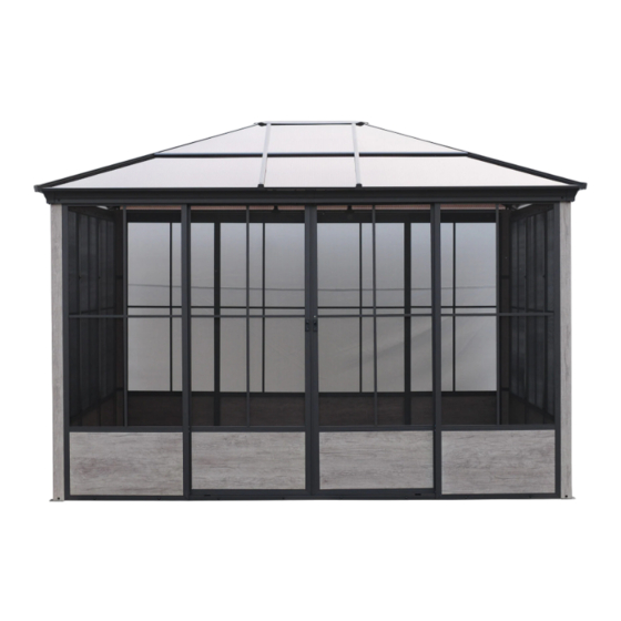
ITEM #5276103
SUNROOM
MODEL
#TPGAZ24109B
Español p. 26
Advertisement

Related Manuals for Allen + Roth TPGAZ24109B


Summary of Contents for Allen + Roth TPGAZ24109B
- Page 1 · sophisticated · inspiring ITEM #5276103 ALLEN + ROTH and logo design are trademarks or registered trademarks of LF, LLC. SUNROOM All rights reserved. MODEL #TPGAZ24109B Español p. 26 ATTACH YOUR RECEIPT HERE Serial Number ___________ Purchase Date ___________ Questions, problems, missing parts? Before returning to your retailer, call our customer service department at 866-439-9800, 8 a.m.
-
Page 2: Table Of Contents
TABLE OF CONTENTS Package Contents ........................3 Hardware Contents ........................5 Safety Information ........................7 Preparation ..........................7 Installation Instructions ........................8 Care and Maintenance ........................ 24 Warranty ............................24 Replacement Parts List ....................... 25... -
Page 3: Package Contents
PACKAGE CONTENTS DESCRIPTION Short left crossbar Base plate Short right crossbar Sliding door upper rail Long left crossbar Sliding door bottom rail Long right crossbar Frame corner connector Front & rear regular frame Door frame support tube Side regular frame Corner protector Sliding door Stopper... - Page 4 PACKAGE CONTENTS DESCRIPTION DESCRIPTION Bottom reinforcement strip Upper center connector Lower center connector Left Edge Short support bar Right Edge Long support bar Mid Edge Left roof joint Short support bar cap Right roof joint Long support bar cap Mid roof joint Left upper panel Upper reinforcement strip Left upper panel...
-
Page 5: Hardware Contents
HARDWARE CONTENTS (NOT TO SCALE) Regular frame plug M6 x 15 mm Bolt Qty. 8 + 2 Extra Qty. 159 + 5 Extra M6 x 15 mm Bolt M4 x 16 mm Bolt Qty. 16 + 1 Extra Qty. 24 + 2 Extra M6 x 15 mm Bolt M6 x 35 mm Bolt Qty. -
Page 6: Safety Information
SAFETY INFORMATION Please read and understand this entire manual before attempting to assemble or install the product. Four people are need for assembly. CAUTION SET UP YOUR GAZEBO PROPERLY • This unit is heavy. Do not assemble this item alone. 4 people are recommended for safe assembly. •... - Page 7 ASSEMBLY INSTRUCTIONS 1.Fix the Base plate (G1) to the Post (G) with Bolts(AA). Hardware Used M6 x 15 mm Washer Wrench 2. Connect the Long left crossbar (C1) and the Long right crossbar (C2) with Bolts (AA ) through the Crossbar inner Connector (F). Hardware Used M6 x 15 mm X 16...
- Page 8 ASSEMBLY INSTRUCTIONS 3.Attach the Stopper (O2) to the Long crossbar (C1/C2) with Bolts (AA), then attach the Connector (V1) to the Long crossbar (C1/C2) with Bolts (AA) Hardware Used M6 x 15 mm X 10 X 10 Washer X 10 Wrench 4.
- Page 9 ASSEMBLY INSTRUCTIONS 5.Attach the Stopper (O2) to the Short crossbar (B1/B2) with bolts (AA). Hardware Used M6 x 15 mm Washer Wrench 6.1 Connect the assembled Short crossbar (B1/B2) and Long crossbar (C1/C2) to the Post (G) with bolts (AA/BB/MM/GG). Note: No need Cap (GG) on outside.
- Page 10 ASSEMBLY INSTRUCTIONS 7.1 Attach the middle hole of he Frame corner connector (J) to the post (G) with Bolts (AA). 7.2 Connect the upper ends of the regular frame ( D1/D2) to the crossbar (C1/C2/B1/B2) with Bolts (CC ), then connect the holes on both sides of the Frame corner connector (J) to the regular frame (D1/D2) with Bolts (AA)
- Page 11 ASSEMBLY INSTRUCTIONS 8.1 Secure the upper ends of the Side regular frame(D1) to the Crossbar (B1/ B2) with Bolt (CC) and Washer (LL). 8.2 Connect the Regular frames(D2) together with Connector (N) by using the Bolts (AA). Hardware Used M6 x 15 mm X 16 M6 x 35 mm X 20...
- Page 12 ASSEMBLY INSTRUCTIONS 10.Connect the Sliding door bottom rail (H) with Bolts (CC) and Washer M6 (LL) by means of Front & rear regular frame (D1) and Door frame support tube Hardware Used M6 x 35 mm X 16 X 16 Washer Wrench-4#...
- Page 13 ASSEMBLY INSTRUCTIONS 11.1 Ins ert the Sliding door upper rail (I) into the top connector of the Sliding door (E1/E2). 11.2 Secure the Rail cap (HH) to both ends of the Sliding door upper rail with Bolts (EE). 11.3 Insert the lower end of the Sliding door into the Sliding door bottom rail (H) , then stand the door up and attach the upper end to the Long crossbar (C1/C2) with Bolts (AA)
- Page 14 ASSEMBLY INSTRUCTIONS...
- Page 15 ASSEMBLY INSTRUCTIONS 12.Insert the Bolts (JJ) into the Lower center connector (A2) from the topend , then screw on the Nuts (KK) by inserting the bottom end. Note: Do not tighten Washer M6 (LL) at the the nut, just screw it halfway to the Bolt.
- Page 16 ASSEMBLY INSTRUCTIONS 14. Insert the two bolts (JJ) Washer M6 (LL) Wrench-5# (OO) into the grooves of the Short support bar (L) as shown in the figure. Hardware Used M6 x 15 mm X 12 X 12 Washer X 12 Wrench 15.
- Page 17 ASSEMBLY INSTRUCTIONS 16. Insert the Rail cap (HH) of the Lower center connector (A2) into theM Short support bar (L), tighten the Rail cap (HH), attach the bottom side of the Short support bar (L) to the Connector (V1) with the Bolts (AA), and fasten the Caps (MM).
- Page 18 ASSEMBLY INSTRUCTIONS 17. Secure the Upper center connector (A1) to the Lower center connector (A2) by the Bolts (AA). 17.2 Cover the Bolt cover (II) onto the Bolts under the Lower Center Connector. Hardware Used M6 x 15 mm Washer Wrench Bolt Cover X 20...
- Page 19 ASSEMBLY INSTRUCTIONS 18. Slide the panel (①③⑤) through the slot of the Support bar (L/M) and adjust the position of the (left/right) upper panel①③⑤.
- Page 20 ASSEMBLY INSTRUCTIONS 19. Insert the Roof joint (P1/P2/P3) into the lower slot of the support bar (L/M). Adjust the position to make sure they are vertically parallel. Repeat for each side. 20.Insert the Panel (②④⑤) into the slot of the Support bar. Adjust the position of the (left/right) lower panel (②④⑤).
- Page 21 ASSEMBLY INSTRUCTIONS 21.1 Put the Edge (S1/S2/S3) onto the Support bar (L/M) with Bolts (AA) and fasten the Caps (MM).Repeat the above steps for the rest of the Edges and Short Support bars . Adjust the position of the Edges to make sure they are vertical and parallel.
- Page 22 ASSEMBLY INSTRUCTIONS 22.1 Attach the ends of the Upper reinforcement strip (Q1/Q2/Q3) to the Long support bar (M) and Short support bar (L) by fixing them to the Bolts (JJ) shown in steps 13 and 14. 22.2 Attach the ends of the Bottom reinforcement strip (R1/R2/R3) to the Long support bar (M) and Short support bar (L), by fixing them to the Bolts (JJ) shown in steps...
- Page 23 ASSEMBLY INSTRUCTIONS 23.Thread the Stakes (RR) through the Base plate (G1) into the ground to secure the gazebo. Hardware Used Stake...
-
Page 24: Care And Maintenance
CARE AND MAINTENANCE • For cleaning, use a mild detergent solution, rinse with water, and allow to air dry. Do not use acetone, abrasive, or other special detergents as they would be harmful to the product’s finish. • Due to the nature of steel, surface oxidation (rusting) will occur if this protective coating is scratched. This is a natural process. -
Page 25: Replacement Parts List
REPLACEMENT PARTS LIST For replacement parts, call our customer service department at 866-439-9800, 8 a.m. - 8 p.m., EST, Monday - Sunday. You could also contact us at partsplus@lowes.com. Regular frame plug M6 x 15 mm Bolt M6 x 15 mm Bolt M6 x 15 mm Bolt M4 x 16 mm Bolt M6 x 35 mm Bolt... - Page 26 · sofisticado · inspirador ARTÍCULO #5276103 ALLEN + ROTH y el diseño del logotipo son marcas comerciales o marcas registradas de LF, LLC. SOLÁRIUM Todos los derechos reservados. MODELO # TPGAZ24109B ADJUNTE EL RECIBO AQUÍ Número de serie ___________ echa de compra ___________ ¿Preguntas, problemas, piezas faltantes? Antes de volver a la tienda, llame a nuestro...
- Page 27 ÍNDICE Contenido del paquete ........................24 Aditamentos ..........................25 Información de seguridad......................26 Preparación ........................... 26 Instrucciones de instalación......................27 Cuidado y mantenimiento....................... 41 Garantía ............................41 Lista de piezas de repuesto ......................42...
- Page 28 CONTENIDO DEL PAQUETE CANTIDAD PIEZA DESCRIPCIÓN CANTIDAD PIEZA DESCRIPCIÓN Barra transversal izquierda corta Placa de base Barra transversal derecha corta Riel superior de puerta corrediza Barra transversal izquierda larga Riel superior de puerta corrediza Barra transversal derecha larga Conector de esquina de la estructura Estructura regular frontal y posterior...
- Page 29 CONTENIDO DEL PAQUETE CANTIDAD CANTIDAD PIEZA DESCRIPCIÓN PIEZA DESCRIPCIÓN Tira de refuerzo inferior Conector central superior Conector central inferior Borde izquierdo Barra de soporte corta Borde derecho Borde central Barra de soporte larga Tapa de barra de Unión de techo izquierda soporte corta Unión de techo derecha Tapa de barra de...
- Page 30 ADITAMENTOS (NO SE MUESTRAN A ESCALA) Tapón de estructura regular Perno M6 x 15 mm Cant. 8 + 2 adicionales Cant. 159 Perno M6 x 15 mm Perno M4 x 16 mm + 5 adicionales Cant. 16 Cant. 24 Perno M6 x 15 mm Perno M6 x 35 mm + 1 adicional + 2 adicionales...
- Page 31 INFORMACIÓN DE SEGURIDAD Lea y comprenda completamente este manual antes de intentar ensamblar o instalar el producto. Para realizar el ensamblaje se necesitan cuatro personas. PRECAUCIÓN ENSAMBLAR EL GAZEBO ADECUADAMENTE • Este módulo es pesado. No ensamble este artículo solo. Se recomienda que haya 4 personas para un ensamblaje seguro.
- Page 32 INSTRUCCIONES DE ENSAMBLAJE 1.Fije la placa base (G1) al poste (G) con pernos (AA). Aditamentos utilizados M6 x 15 mm Arandela Tapa Llave inglesa 2. Conecte la barra transversal izquierda larga (C1) y la barra transversal derecha larga (C2) con pernos (AA) a través del conector interior de la barra transversal (F).
- Page 33 INSTRUCCIONES DE ENSAMBLAJE 3. Conecte el tope (O2) a la barra transversal larga (C1/C2) con pernos (AA), luego conecte el conector (V1) a la barra transversal larga (C1/C2) con pernos (AA). Aditamentos utilizados M6 x 15 mm X 10 X 10 Arandela X 10 Tapa...
- Page 34 INSTRUCCIONES DE ENSAMBLAJE 5. Fije el tope (O2) a la barra transversal corta (B1/B2) con pernos (AA). Aditamentos utilizados M6 x 15 mm Arandela Tapa Llave inglesa 6.1 Conecte la barra transversal corta ensamblada (B1/B2) y la barra transversal larga (C1/C2) al poste (G) con pernos (AA/BB/MM/GG).
- Page 35 INSTRUCCIONES DE ENSAMBLAJE 7.1 Fije el orificio central del conector de esquina de la estructura (J) a la Poste (G) con pernos (AA) individualmente. 7.2 Conecte los extremos superiores de la estructura regular (D1/D2) a la barra transversal (C1/C2/B1/B2) con pernos (CC), luego conecte los orificios en ambos lados del conector de esquina de la estructura (J) a la estructura regular (D1/...
- Page 36 INSTRUCCIONES DE ENSAMBLAJE 8.1 Asegure los extremos superiores de las dos R a la barra transversal (B1/B2) con pernos (CC) y arandelas (LL). 8.2 Fije la placa Estructura regular lateral (D2) together con Conector (N) con pernos (AA). Aditamentos utilizados M6 x 15 mm X 16 M6 x 35 mm...
- Page 37 INSTRUCCIONES DE ENSAMBLAJE 10. Conecte el riel inferior de la puerta corrediza (H) con pernos (CC) y arandelas M6 (LL) con el uso de las estructuras regulares frontal y posterior (D1) y el tubo de soporte del marco para puerta. Aditamentos utilizados M6 x 35 mm X 16...
- Page 38 INSTRUCCIONES DE ENSAMBLAJE 11.1 Inserte el riel superior de la puerta corrediza (I) en el conector superior de la puerta corrediza (E1/E2). 11.2 Asegure la tapa del riel (HH) a ambos extremos del riel superior de la puerta corrediza con pernos (EE). 11.3 Inserte el extremo inferior de la puerta corrediza en el riel inferior de la puerta corrediza (H), luego levante la puerta y fije...
- Page 39 INSTRUCCIONES DE ENSAMBLAJE...
- Page 40 INSTRUCCIONES DE ENSAMBLAJE 12. Inserte los pernos (JJ) en el conector central inferior (A2) desde el extremo superior, luego enrosque las tuercas (KK) al insertar el extremo inferior. Nota: no apriete la arandela M6 (LL) en la tuerca, solo enrósquela hasta la mitad del perno.
- Page 41 INSTRUCCIONES DE ENSAMBLAJE 14. Inserte los dos pernos (JJ), arandelas M6 (LL) con la llave inglesa 5# (OO) en las ranuras de la barra de soporte corta (L), como se muestra en la figura. Aditamentos utilizados M6 x 15 mm X 12 X 12 Arandela...
- Page 42 INSTRUCCIONES DE ENSAMBLAJE 16. Inserte la tapa del riel (HH) del conector central inferior (A2) en la barra de soporte corta M (L). Apriete la tapa del riel (HH), fije el lado inferior de la barra de soporte corta (L) al conector (V1) con los pernos (AA) y fije las tapas (MM).
- Page 43 INSTRUCCIONES DE ENSAMBLAJE 17. Asegure el conector central superior (A1) al conector central inferior (A2) con los pernos (AA). 17.2 Cubra la cubierta para perno (II) sobre los pernos debajo del conector central inferior. Aditamentos utilizados M6 x 15 mm Arandela Tapa Llave inglesa...
- Page 44 INSTRUCCIONES DE ENSAMBLAJE 18. Deslice el panel (①③⑤) a través de la ranura de la barra de soporte (L/M) y ajuste la posición del panel superior (izquierdo/derecho) ①③⑤.
- Page 45 INSTRUCCIONES DE ENSAMBLAJE 19.Inserte la unión de techo (P1/P2/P3) en la ranura inferior de la barra de soporte (L/M). Ajuste la posición para asegurarse de que estén verticalmente paralelas. Repita para cada lado. 20. Inserte el panel (②④⑤) en la ranura de la barra de soporte.
- Page 46 INSTRUCCIONES DE ENSAMBLAJE 21.1 Coloque el borde (S1/S2/S3) en la barra de soporte (L/M) con pernos (AA) y ajuste las tapas (MM). Repita los pasos anteriores para el resto de los bordes y las barras de soporte cortas. Ajuste la posición de los bordes para asegurarse de que estén verticales y paralelos.
- Page 47 INSTRUCCIONES DE ENSAMBLAJE 22.1 Fije los extremos de la tira de refuerzo superior (Q1/Q2/Q3) a la barra de soporte larga (M) y la barra de soporte corta (L), fíjelos a los pernos (JJ) que se muestran en los pasos 13 y 14. 22.2 Fije los extremos de la tira de refuerzo inferior (R1/R2/R3) a la barra de soporte larga (M) y la barra de soporte corta (L) al...
- Page 48 INSTRUCCIONES DE ENSAMBLAJE 23.Pase las estacas (RR) a través de la placa base (G1) y fíjelas en el suelo para asegurar el gazebo. Aditamentos utilizados Estaca...
- Page 49 CUIDADO Y MANTENIMIENTO • Para limpiar, use una solución de detergente suave, enjuague con agua y deje secar al aire. No use acetona, productos abrasivos u otros detergentes especiales porque dañarían el acabado del producto. • Debido a la naturaleza del acero, puede producirse una oxidación superficial si este recubrimiento protector se raya.
- Page 50 LISTA DE PIEZAS DE REPUESTO Para obtener piezas de repuesto, llame a nuestro Departamento de Servicio al Cliente al número 866-439-9800, de 8 a.m. a 8 p.m., hora estándar del Este. También puede ponerse en contacto con nosotros en partsplus@lowes.com. Tapón de estructura regular Perno M6 x 15 mm Perno M6 x 15 mm...
Need help?
Do you have a question about the TPGAZ24109B and is the answer not in the manual?
Questions and answers