Table of Contents
Advertisement
Advertisement
Table of Contents

Related Manuals for LiteGear LITEDIMMER SPECTRUM AC/DC 200

Summary of Contents for LiteGear LITEDIMMER SPECTRUM AC/DC 200
- Page 1 LiteDimmer Spectrum AC/dc 200 & 400 USERS GUIDE...
- Page 2 © 2023 LITEGEAR, INC. All rights reserved. Information subject to change without notice. LiteGear and all affiliated companies disclaim liability for any injury, damage, direct or indirect loss, consequential or economic loss or any other loss occasioned by the use of, inability to use or reliance on the information contained in this document.
-
Page 3: Table Of Contents
Index Safety Information Art-Net/sACN ........21-22 Technical Specifications ..51-52 Dangers ............1 CRMX Settings ......23-24 Dimensions ........... 53 Local Control ........25 Maintenance ........... 54 Notices ............1 Output Settings ......26-27 Help..............54 Warning ............2 Certifications .......... 55 Introduction ..........3 Display Settings ......... -
Page 4: Dangers
DANGER • Repairs must be performed by LiteGear or an authorized service agent. • Maintenance to be performed only when identified in this user guide. • Hight voltage! Risk of electric shock and fire. • Follow all safety information and operation instructions before operating or installing this product or system. -
Page 5: Warning
WARNING Risk of electric shock from high humidity. • Do not operate or expose this product to rain or moisture. • If the product is exposed to moisture, allow unit to dry for a period of 4 hours to prevent any electrical damage from occurring to electrical components. -
Page 6: Introduction
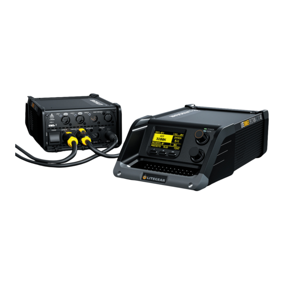
Introduction LiteDimmer Spectrum AC/DC 200 and LiteDimmer Spectrum AC/DC 400 are part of a new class of dimmers packed with great new features, an ergonomic design, and ultra-compact form factor. Complete with local control and industry leading communication protocols, the LiteDimmer Spectrum AC/DC 200 and LiteDimmer Spectrum AC/DC 400 can control multiple large-format pixels, making pixel mapping of the LiteMat Spectrum easier than ever. -
Page 7: Features
Features Hardware Features • Simple and intuitive user interface. • Convenient of connecting data and power. • Advanced processing power. • Advanced color control • Expanded memory • Software updates via a USB-A port. • Ethernet-based communication. • Integrated Network Switch •... - Page 8 Features Software Features Streaming ACN (E1.31) is fully implemented in the LiteDimmer Spectrum AC/DC 200 and the LiteDimmer Spectrum AC/ DC 400. This standard ethernet-based protocol efficiently transports DMX universes over the network and eliminates the need for a DMX gateway.
-
Page 9: Overview
Overview Front Panel (Controls) - Page 10 Overview Front Panel (Controls) 1. OLED Display - Offers an intuitive navigation for the LiteDimmer Spectrum AC/DC 200 and LiteDimmer Spectrum AC/ DC 400 control center. 2. Function Buttons - Allows for effortless interface selections when used in conjunction with the encoders.
-
Page 11: Back Panel (Connections)
Overview Back Panel (Connections) - Page 12 Overview Back Panel (Connections) 8. Power Switch - Integrated power switch acts as both a breaker and on/off switch. 9. USB-A Port - The integrated port allows for quick and easy firmware updates. 10. EtherCon Ports - Supports Art-Net and sACN communication protocols and features an Art-Net/sACN gateway and an integrated network switch..
-
Page 13: Top & Bottom (Features)
Overview Base 16. Multi-Function Handle - Conveniently allows the dimmer to be carried and provides a sturdy attachment point 17. K-Mount Plate - Quickly and easily attach any LiteGear K-Mount accessory. -
Page 14: Connecting 28-Pin Cable
Overview Connections Best practices for connecting to and disconnecting from the connector. 1. Toggle the Power Switch to the OFF position. 2. Insert the cable connector into the PDX OUT port until the connector locks in place. 3. Toggle the Power Switch to the ON position. Best practices for connecting to and disconnecting from the Battery... -
Page 15: Installation
LiteDimmer Truss Mount The LiteDimmer truss mount provides secure attachment of the LiteDimmer Spectrum AC/DC 200 or the LiteDimmer Spectrum AC/DC 400 to any 1.5” to 2” pipe. A k-Mount enables quick attachment to the AC600 while the 2” cheeseborough affixes firmly to almost any pipe. -
Page 16: Litedimmer Stand Mount
LiteDimmer Stand Mount The LiteDimmer Stand Mount provides a secure attachment of the LiteDimmer Spectrum AC/DC 200 or the LiteDimmer Spectrum AC/DC 400 to a light stand. A k-Mount enables quick attachment to the AC600, while the Super Clamp affixes firmly to the stand stem. -
Page 17: Dmx Settings
Settings DMX Settings DMX Settings allows the user to control the fixture through any DMX control device. The user can connect through wired or wireless DMX. When using wired DMX it is possible to daisy-chain between units. OS 3.0 DMX operation includes its collection of DMX settings that are separate from Local settings. -
Page 18: Dmx Address
Settings DMX Settings - DMX Address DMX Address mode allows the user to set a desired DMX Address. 1. Press function button below SETTINGS. 2. Rotate the top encoder knob to navigate to DMX SETTINGS and press the top encoder knob to select. 3. -
Page 19: Dmx Personalities
9. Spectrum RGBATD, 16b 21. V.RGB, Spectrum, 16b DMX Personalities, scan the 10. Spectrum RGBATD, Pixel 8b 22. V.RGB, Spectrum, Pixel 8b QR code above or go to 11. Spectrum RGBATD, Pixel 16b 23. V.RGB, Spectrum, Pixel 16b litegear.com/spectrum-os-resources/ 12. RGBATD, 8b... -
Page 20: Dmx Loss Behavior
Settings DMX Settings - Loss Behavior DMX Loss Behavior mode allows the user to save or erase DMX settings after unplugging the dimmer. 1. Press function button below SETTINGS. 2. Rotate the top encoder knob to navigate to DMX SETTINGS and press the top encoder knob to select. 3. -
Page 21: Rdm State
Settings DMX Settings - RDM State RDM State enable the user to turn the RDM functionality on or off. 1. Press function button below SETTINGS. 2. Rotate the top encoder knob to navigate to DMX SETTINGS and press the top encoder knob to select. 3. -
Page 22: Fixture #/Universe Assignment
Settings DMX Settings - Fixture # Fixture # allows for setting the fixture number. Universe Assignment allows for labeling the DMX universe (Note: This does not set the DMX Universe) 1. Press function button below SETTINGS. 2. Rotate the top encoder knob to navigate to DMX SETTINGS and press the top encoder knob to select. 3. -
Page 23: Load-In Presets
Settings DMX Settings - Load-In Presets allows for the storage and loading of up to 10 DMX setups. Setup parametrs include: Series, Personality, Art-Net Network, Art-Net Subnet, Art-Net Universe, sACN Universe 1. Press function button below SETTINGS. 2. Rotate the top encoder knob to navigate to DMX SETTINGS and press the top encoder knob to select. 3. -
Page 24: Art-Net/Sacn
Settings Art-Net/sACN Art-Net/sACN allows the user to choose the desired communication protocol. 1. Press function button on the display below SETTINGS. 2. Rotate the top encoder knob to navigate to ART-NET & sACN and press the top encoder knob to select. 3. - Page 25 Settings Art-Net/sACN (Continued) Art-Net Universe: - SET UNIVERSE NUMBER choose the universe you would like to join. Range from 0 to 15. • Once the universe has selected, press function button on the display below SET. Merge Mode: - Last Take Preced - High Take Preced Gateway: Gateway: (Sends the Art-Net or sACN DMX data to the 5-Pin DMX Thru Connector) sACN Universe:...
-
Page 26: Crmx Settings
Settings CRMX Settings CRMX settings allows the user to select the DMX transmit/receive state. CRMX State 1. Press function button on the display below SETTINGS. 2. Rotate the top encoder knob to navigate to CRMX SETTINGS and press the top encoder knob to select. 3. - Page 27 Settings CRMX Settings (Continued) Off: - Rotate the top encoder knob to navigate to OFF and press the top encoder knob to select. - VERIFY if CRMX State is off. DMX Transmit - if ON, then the incoming CRMX DMX data is sent to the 5-Pin DMX Thru Connector 1.
-
Page 28: Local Control
Settings Local Control Local Control allows the user to control the fixture through the 2 encoders and set of 3 function buttons below the OLED display. PIXEL MODE is not accessible when using the dimmer manually. To learn about pixel see “Pixel”... -
Page 29: Output Settings
Settings Output Settings Output Settings allow for the adjustment of the dimmer color space, pixel handling, and power limiting features. These setting apply both with local control and via DMX. 1. Press function button on the display below SETTINGS. 2. Rotate the top encoder knob to navigate to OUTPUT SETTINGS and press the top encode knob to select. 3. - Page 30 Settings Output Settings (Continued) Pixel Handling Options: - SET PIXEL QTY choose how many pixels you would like to control. The range is from 1 to 4 pixels for the LiteDimmer Spectrum AC/DC 200. The range is from 1 to 8 for the LiteDimmer Spectrum AC/DC 400. Power Limit Options: - Set a limit for the total power the dimmer is able to consume.
-
Page 31: Display Settings
Settings Display Settings Display Settings allow the user to control the OLED display screen’s illuminated time. The display also allows users to select the screen rotation depending on the orientation of the dimmer. 1. Press function button on the display below SETTINGS. 2. -
Page 32: Dimmer Firmware Update
Settings USB Functions - Updating Dimmer Firmware USB Functions /Updating Dimmer Firmware allow the user to install /update the dimmer firmware. 1. Press function button on the display below SETTINGS. 2. Rotate the top encoder knob to navigate to USB FUNCTIONS and press the top encoder knob to select. 3. -
Page 33: Pixel Firmware Update
Settings USB Functions- Updating Pixel Firmware (Dimmer must be connected to fixture to update pixel firmware) USB Functions/Updating Pixel Firmware allow the user to install/update the pixel engine firmware. 1. Press function button on the display below SETTINGS. 2. Rotate the top encoder knob to navigate to USB FUNCTIONS and press the top encoder knob to select. 3. -
Page 34: Save/Load Settings
Settings USB Functions- Save/Load Settings allows for the saving or loading of all of the settings for the ballast (cloning) using a USB flash drive 1. Press function button on the display below SETTINGS. 2. Rotate the top encoder knob to navigate to USB FUNCTIONS and press the top encoder knob to select. 3. -
Page 35: Save Service Log
Settings USB Functions- Save Service Log allows for saving the Ballast Service Log to a USB flash drive 1. Press function button on the display below SETTINGS. 2. Rotate the top encoder knob to navigate to USB FUNCTIONS and press the top encoder knob to select. 3. -
Page 36: Format Usb Drive
Settings USB Functions- Format USB Drive will format a USB drive to FAT16 or FAT32 as appropriate for use in the AC/DC200, AC/ DC400 or AC600. This operation also copies FW files to the newly formated drive, so that it can be used to update other ballasts. -
Page 37: Network Settings
Settings Network Settings Network Settings allow the user to select and verify network status, addresses, and information. 1. Press function button on the display below SETTINGS. 2. Rotate the top encoder knob to navigate to NETWORK SETTINGS and press the top encoder knob to select. 3. - Page 38 Settings Network Settings (Continued) IP Mode: - Rotate the top encoder knob to navigate to IP MODE and press the top encoder knob to select. - Rotate the top encoder knob to navigate to select desired IP MODE and press the top encoder knob to select. - DHCP - Art-Net 2.x.x.x - Art-Net 10.x.x.x...
- Page 39 Settings Network Settings (Continued) IP Gateway: - Rotate the top encoder knob to navigate to GATEWAY and press the top encoder knob to select. - Rotate the top encoder knob to input desired IP GATEWAY. - Verify IP GATEWAY is correct. - Press function button on the display below SET.
- Page 40 Settings Network Settings (Continued) Observe MAC ADDRESS: - Rotate the top encoder knob to navigate to MAC ADDRESS and press the top encoder knob to select. - Verify IP MAC ADDRESS is correct. Observe NETWORK DEVICE NAME: - Rotate the top encoder knob to navigate to NETWORK DEVICE NAME and press the top encoder knob to select. - Verify IP NETWORK DEVICE NAME is correct.
-
Page 41: System Info
Settings System Info System Info allows the user to view dimmer information such as System status, Dimmer Info, Pixel Info, Help, and System Copyright. 1. Press function button on the display below SETTINGS. 2. Rotate the top encoder knob to navigate to System Info and press the top encoder knob to select. 3. - Page 42 Settings System Info- System Status 1. Press function button on the display below SETTINGS. 2. Rotate the top encoder knob to navigate to System Info and press the top encoder knob to select. 3. Rotate the top encoder knob to navigate to SYSTEM STATUS and press the top encode knob to select. 4.
- Page 43 Settings System Info Pixel Info 1. Press function button on the display below SETTINGS. 2. Rotate the top encoder knob to navigate to System Info and press the top encoder knob to select. 3. Rotate the top encoder knob to navigate to PIXEL INFO and press the top encode knob to select. 4.
- Page 44 Settings System Info Help 1. Press function button on the display below SETTINGS. 2. Rotate the top encoder knob to navigate to System Info and press the top encoder knob to select. 3. Rotate the top encoder knob to navigate to HELP and press the top encode knob to select. 4.
-
Page 45: Utilities
Settings Utilities Utilities allow the user to assign lf-pixels and to set and test lf-pixels. 1. Press function button on the display below SETTINGS. 2. Rotate the top encoder knob to navigate to UTILITIES and press the top encoder knob to select. 3. -
Page 46: Set Real Time Clock
Settings Utilities - Set the Real Time Allows for the setting of the clock which is used for timestamping events and files. 1. Press function button on the display below SETTINGS. 2. Rotate the top encoder knob to navigate to UTILITIES and press the top encoder knob to select. 3. -
Page 47: Clear Service Logs
Settings Utilities - Clear Service Logs Clears the Service Logs (the Service Logs are not cleared during a Factory Reset) 1. Press function button on the display below SETTINGS. 2. Rotate the top encoder knob to navigate to UTILITIES and press the top encoder knob to select. 3. -
Page 48: Factory Reset
Settings Factory Reset Reset will reset all settings, modes, profiles, and DMX selections to the factory defaults. (Service Log is not Cleared. See Utilities) 1. Press function button on the display below SETTINGS. 2. Rotate the top encoder knob to navigate to FACTORY RESET and press the top encoder knob to select. 3. -
Page 49: Functions
Functions Setting Tint in True Hybrid and Spectrum Modes Pressing the Tint button allows for ±Magenta/Green Color Correction. There are 100 steps of Green (+) and 100 steps of Magenta (-) correction from neutral (0). When the desired Tint is selected, press DONE to return to the previous screen or simply remain at the screen that shows all parameters. -
Page 50: Audition
Functions Audition Audition, available in local modes, allows the operator to fade the output OFF and then back ON, allowing for previewing lighting. 1. Press the bottom encoder knob. 2. Press function button below AUD (on the OLED display) to active and hold as required. To inactive simply release. -
Page 51: Parameter Presets
Functions Parameter Presets Parameter Presets exist for each main parameter, CCT, Accent Color, and Saturation. Six factories presets are available at your fingertips. Easily invoke the feature by short-pressing the top screen-side button. Three of the most common presets are offered on the lower line of the display and a slight turn of the top encoder shows additional options. A short-press of the top encoder cycles through parameters. -
Page 52: Cue Function
Functions Cue Function Cue Function operates like global-presets with a dedicated playback screen. This feature consists of three “looks” including two standard looks and one momentary look. 1. Press the bottom encoder knob to select. 2. Set the color you would like to store in a cue. 3. -
Page 53: Error Codes
Error Codes Pixel Faults Com Flt: Faulty Dimmer to Pixel communications Over A: Pixel current exceeds circuit rating. (1.8A) Undr VW: Pixel supply voltage nears low voltage circuit rating. (44V) Over VW: Pixel supply voltage approaches high voltage limit. (51V) Over VF: Pixel supply voltage exceeds high voltage limit. -
Page 54: Specifications
Specifications LiteDimmer Spectrum AC/DC 200 Technical Specifications Input Voltage: 100 – 240V AC, 50/60 Hz Input Current: 3A Output Voltage: 48V DC Output Current: 5A Data Connectors: USB-A, 2x EtherCon, 5-Pin DMX In and Thru, Internal CRMX Antenna Data Connectors: PDX... - Page 55 Specifications LiteDimmer Spectrum AC/DC 400 Technical Specifications Input Voltage: 100 – 240V AC, 50/60 Hz Input Current: 4.5A Output Voltage: 48V DC Output Current: 9.25A Data Connectors: USB-A, 2x EtherCon, 5-Pin DMX In and Thru, Internal CRMX Antenna Data Connectors: PDX Mains Power Connectors: powerCON TRUE1 TOP In and Thru (Edison / Schuko / Bare Ends cables available) Control: DMX, RDM, CRMX, Art-Net, sACN Switches: On-board On/Off Switch...
- Page 56 Specifications LiteDimmer Spectrum AC/DC 200 and LiteDimmer Spectrum AC/DC 400 Dimensions 104.4 7.3 in (185 mm) 185.0 13.3 in (338.6 mm) 13.3 338.6...
-
Page 57: Maintenance
Pressing the function button below HELP on the Welcome Screen provides access to a QR code that will link your smart phone or tablet to the Spectrum support page on the LiteGear website. Here you will find resources to answer many common questions. -
Page 58: Certifications
Certifications... - Page 59 For additional information on your Auroris and LiteDimmer Spectrum AC/DC 200 & 400, visit us at litegear.com/litemat-spectrum...
Need help?
Do you have a question about the LITEDIMMER SPECTRUM AC/DC 200 and is the answer not in the manual?
Questions and answers