Table of Contents
Advertisement
Available languages
Available languages
Quick Links
Advertisement
Chapters
Table of Contents

Related Manuals for Midland BENCHMARK HH0407

Summary of Contents for Midland BENCHMARK HH0407
- Page 1 5140-041 HH0407 MANUAL...
- Page 2 This product is supported by Midland Power. Contact us directly for assistance and warranty help. Do not return this product to store. You must register online for your warranty to be valid. It only takes a minute, do it now while you still have your purchase receipt.
- Page 3 Thanks for choosing the HH0407! You're excited to get started, we'll keep this brief. READ THIS ENTIRE GUIDE BEFORE USING THIS PRODUCT AND SAVE FOR LATER USE. This user guide contains important instructions including safety, setup, operation, and maintenance that must be followed. All information in this guide is based on information available at the time of print.
-
Page 4: Table Of Contents
TABLE OF CONTENTS 1. Safety 2. Learn About Your Tiller 3. Getting Started 4. Pre-Operation Check 5. Starting the Engine 6. Stopping the Engine 7. Using the Tiller 7.1 Adjusting the Depth Regulator 7.2 Adjusting the Tilling Width 7.3 Adjusting the Wheel Links 7.4 Engaging the Tines and Wheels 8. -
Page 5: Safety
1. SAFETY WARNING! This product can expose you to chemicals including carbon monoxide, which is known to the State of California to cause cancer and birth defects or other reproductive harm. For more TOXIC FUMES HAZARD. Running engines give off information go to www.P65Warnings.ca.gov carbon monoxide, an odourless poisonous gas that can cause nausea, fainting, or death. - Page 6 Place the tiller at least 3 feet away from buildings or other equipment during operation. Know how to stop the tiller quickly and understand operation of all the controls. Never permit anyone to operate the tiller without proper instructions.
- Page 7 causing personal injury or property damage. Watch for holes, roots, bumps, or other rough ground. Tall grass can hide obstacles. Always look behind and down and use caution when using reverse or pulling the tiller towards you. Never attempt to start the tiller unless both wheels are locked in the same position.
- Page 8 Only qualified maintenance personnel with knowledge of fuels and machinery hazards should perform maintenance procedures. See ‘Maintenance Schedule’ for the recommended maintenance schedule.
-
Page 9: Learn About Your Tiller
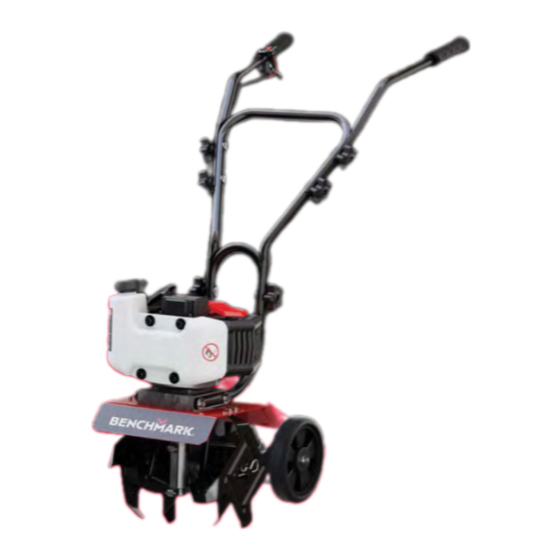
2. LEARN ABOUT YOUR TILLER This section will show you how to identify key parts of your tiller. Going over the terminology below will make sure we’re on the same page. 2.1 COMPONENT IDENTIFICATION ON/OFF Switch Fuel Cap Tines Throttle Control Lever Recoil Starter Choke Lever... - Page 10 2.2 CONTROL FUNCTIONS Choke Lever A carburetor choke lever engages or disengages the choke, subsequentially adjusting the amount of air that is enabled to flow through the intake of the carburetor. Depth Regulator In hard compacted soil, it helps restrain the tiller’s forward motion. In looser soil, it controls how deeply the tines can dig into the ground.
-
Page 11: Getting Started
3. GETTING STARTED Setup of your tiller is designed to get you up and running as quickly as possible. Cut the four corners of the carton from top to bottom instead of attempting to lift it out of the box. 3.1 ASSEMBLING THE DEPTH REGULATOR Remove the pin from the depth regulator bracket. - Page 12 3.2 ASSEMBLING THE HANDLES Using the knobs and screws, position and secure the lower handle bar to the handle mounting bar on the main body.
- Page 13 Secure the lateral handle bars to either side of the lower handle bar with the screws and knobs provided. HH0407...
- Page 14 Ensure that the lateral handle bar with the throttle control lever is on your right-hand side. Throttle Control Lever Right-hand Side...
- Page 15 3.3 ADD FUEL AND ENGINE OIL WARNING! Used motor oil can cause skin irritations if left in long-term contact with skin. Thoroughly wash off used oil as soon as possible with soap and water. Gasoline is highly flammable and explosive under certain conditions.
- Page 16 SAE 10W-30 oil is recommended for general use. DO NOT OVERFILL. Effective Viscosity Range of Engine Oils 15W-50 Synthetic 5W-30 10W-30 5W-30 0°C °C 32°F °F...
-
Page 17: Pre-Operation Check
4. PRE-OPERATION CHECK WARNING! Exhaust gas contains poisonous carbon monoxide. NEVER run the tiller in an enclosed area. Be sure to provide adequate ventilation. Operate the tiller on a level surface. If the tiller is tilted, fuel spillage may result. Keep away from rotating parts while the tiller is running. - Page 18 SAE 10W-30 oil is recommended for general use. DO NOT OVERFILL. 4.2 SURVEY YOUR AREA Familiarize yourself with the area in which you plan to operate the tiller. Mark off all boundaries of where you plan to till. ...
-
Page 19: Starting The Engine
5. STARTING THE ENGINE DANGER! Using a gas powered engine indoors WILL KILL YOU IN MINUTES. Engine exhaust contains high levels of carbon monoxide (CO), a poisonous gas you cannot see or smell. If you can smell the engine exhaust, you are breathing CO. Even if you cannot smell the exhaust, you could be breathing CO. - Page 20 5.1 MANUAL RECOIL START Set the On/Off switch on the right handlebar to the ON position Set the choke lever to the START position. Push the primer bulb 6 times, waiting 2 seconds between each push. Stop when you see the fuel flowing from the fuel tank to the carburetor through the transparent hose.
- Page 21 Move the choke lever to the RUN position. Pull the recoil handle rapidly until engine starts. Carefully allow recoil handle to return. Repeat until engine starts. HH0407...
-
Page 22: Stopping The Engine
6. STOPPING THE ENGINE To stop the engine, turn engine ON/OFF switch to the OFF position. Set the choke lever to the START position. -
Page 23: Using The Tiller
7. USING THE TILLER 7.1 ADJUSTING THE DEPTH REGULATOR WARNING! Always release the throttle lever back to the neutral position and stop the engine before adjusting the depth regulator. Adjust the depth regulator up one hole at a time, testing tiller operation after each change. -
Page 24: Adjusting The Tilling Width
7.2 ADJUSTING THE TILLING WIDTH Tilling width is controlled by the placement of the tines. There are 2 types of tines. One has all 4 teeth facing the same direction; the other has 2 teeth facing in the opposing direction. All 4 tips of the blade are 2 tips are pointing in the opposing pointing the same direction. - Page 25 All 4 tips of the blade are 2 tips are pointing in the opposing For 12 in (30 cm) Tilling Width: pointing the same direction. direction to the other two. HH0407...
- Page 26 For 9.7 in (25 cm) Tilling Width...
-
Page 27: Adjusting The Wheel Links
7.3 ADJUSTING THE WHEEL LINKS There are 3 grooves in the connector plate. Position the wheels in the highest groove (Slot 3) when operating the tiller. Position the wheels in Slots 1 or 2 when the tiller is not in operation. Pull hard on the wheel assembly to release the spring lock. -
Page 28: Engaging The Tines And Wheels
7.4 ENGAGING THE TINES AND WHEELS Engage the tines by squeezing the throttle lever to the handle. - Page 29 Releasing the lever stops the tines and brings the tiller to a stationary position. NOTE Always fully engage the throttle lever when tilling. Always keep distance between yourself and the tiller. Any contact with the rotating tines can result in serious injury. ...
-
Page 30: Tilling Tips
8. TILLING TIPS 8.1 TILLING To allow for machine cultivating after the plants have grown, leave enough clearance room for the tiller between the seed rows. When tilling unbroken ground or extremely hard soil, till at a shallow height by setting the clevis pin in the highest hole of the depth regulator. -
Page 31: Maintenance
9. MAINTENANCE WARNING! Fuel and its vapors are extremely flammable, which could cause burns or fire resulting in death or serious injury. When performing maintenance that requires the unit to be tipped, the fuel tank must be empty, or fuel can leak out and result in a fire or explosion. -
Page 32: Maintenance Schedule
9.1 MAINTENANCE SCHEDULE Regular maintenance will improve performance and extend the service life. Maintain the tiller according to the maintenance schedule below. NOTE Service more frequently when used in dusty areas or adverse conditions. These items should be serviced by an authorized service center unless you have the proper tools and are mechanically proficient. -
Page 33: Cleaning The Air Filter
9.2 CLEANING THE AIR FILTER Air Filter Air Filter Cover Remove the screw securing the silencer cover and open. Remove the sponge air filter. Wash the sponge air filter with detergent and water. Rinse thoroughly when cleaned. Squeeze out all excess water and allow to dry completely. Lightly coat the sponge air filter with engine oil. -
Page 34: Spark Plug Service
9.3 SPARK PLUG SERVICE NOTE Do NOT rinse spark plug in water. Follow guidelines and be careful not 0.5 mm to overtighten the spark plug. (0.02 in) Recommended spark plug: RDJ7Y Check the spark plug gap and clean the carbon deposits at the bottom of the spark plug. -
Page 35: Lubricating The Tiller
Reinstall the spark plug cap. Reinstall the spark plug maintenance cover. NOTE The spark plug must be securely tightened or it could cause the spark plug to heat up enough to damage the engine. Never use a spark plug with an improper heat range. 9.4 LUBRICATING THE TILLER Unscrew the screw that closes the gear box. -
Page 36: Carburetor Modification For High Altitude Operation
9.7 CARBURETOR MODIFICATION FOR HIGH ALTITUDE OPERATION (Above 2,000 feet) NOTE This engine is equipped to run at altitudes below 2,000-ft. A high-altitude main jet is recommended when operated at 2,000 to 7,000-ft above sea level. At elevations above 7,000-ft the engine may experience decreased performance even with a high-altitude main jet. - Page 37 Carburetor Assembly Fuel Cup Seal Mixing Tube (might remain inside carburetor) Main Jet Fuel Cup Washer Drain Bolt Bolt Seal Bolt Turn off the engine. Close the fuel valve. Place a bowl under the fuel cup to catch any spilled fuel. Unthread the bolt holding the fuel cup.
-
Page 38: Transportation & Storage
10. TRANSPORTATION & STORAGE 10.1 DRAINING THE FUEL TANK Drain the old fuel and completely fill the tank with fresh gas and oil mixture. Add a fuel stabilizer according to the manufacturer’s directions to keep your fuel fresh over long periods, we recommend B3C fuel additives. Run the engine for 2 minutes to circulate the fuel stabilizer. - Page 39 Storage Duration Preparation Required Less than 1 Month No storage preparation required, simply store as is. 1 Month to 1 Year Drain the old gas and completely fill the tank with fresh gas before storage. Add fuel stabilizer according to the manufacturer’s directions.
-
Page 40: Troubleshooting
11. TROUBLESHOOTING Problem Cause Solution Engine difficult to Out of fuel. Add fresh fuel. start. Engine Switch OFF. Turn engine switch ON. Engine is not primed. Press the primer bulb 3 times. Spark plug wire disconnected. - Page 41 Tines will not rotate. Debris interfering Remove debris from with the tines. around tines. Tines are loose. Replace tine bolts and nuts. Damaged drive belts. Replace drive belts. Engine will not stop. Check the switch. ...
-
Page 42: Technical Specifications
12. TECHNICAL SPECIFICATIONS SPECIFICATIONS PARAMETERS Type Two Stroke Engine Displacement 52cc Engine Speed 7500 rpm Spark Plug RDJ7Y Spark Plug Gap 0.02 in (0.5mm) Start System Recoil Start Fuel Type Unleaded Gasoline Fuel Tank Volume 0.23 Gal / 1 L Model Name HH0407 Tilling Width... -
Page 43: Limited Warranty
Midland or an authorized service center, show a defect in workmanship or material. Valid proof of purchase must be submitted online for registration with Midland, or presented to Midland at time of claim, for warranty to be valid. This warranty is not transferable from the original owner. - Page 44 This warranty is the entire and only warranty given by Midland for Midland products or equipment. No agent or employee is authorized to extend or enlarge this warranty on behalf of Midland by any written or verbal statement or advertisement.
- Page 45 Emission Control System Warranty Parts: This list applies to parts supplied by Midland Power Inc. and does not cover parts supplied by the equipment manufacturer. Please see the original equipment manufacturer’s emissions warranty for non-Midland Power Inc. parts. Consumable parts are covered up to a maximum of 30 days.
- Page 46 Enjoy! Be sure to check www.benchmark.midlandpowerinc.com for updates regarding your product.
- Page 47 Customer Service Online: www.benchmark.midlandpowerinc.com E-mail: support@midlandpowerinc.com Toll Free: 1-877-528-3772...
- Page 48 HH0407...
- Page 49 5140-041 HH0407 MANUEL...
- Page 50 Ce produit est pris en charge par Midland Power. Contactez-nous directement pour obtenir de l’aide sur la garantie et tout autre assistance. Ne retournez pas ce produit en magasin. Vous devez vous enregistrer en ligne pour valider votre garantie. Cela ne prend qu’une minute… faites-le maintenant pendant que vous avez toujours votre reçu d’achat.
- Page 51 Merci d’avoir choisi le HH0407 ! Vous avez hâte de démarrer, alors nous garderont cette section courte. LISEZ CE GUIDE EN ENTIER AVANT D’UTILISER CE PRODUIT ET CONSERVEZ-LE POUR UNE UTILISATION ULTÉRIEURE. Ce guide de l’utilisateur comprend des instructions importantes à suivre sur la sécurité, la configuration, le fonctionnement et l’entretien du produit.
- Page 52 TABLE DES MATIÈRES 1. Sécurité 2. Renseignez-vous sur votre motoculteur 3. Pour commencer 4. Vérification avant utilisation 5. Démarrage du moteur 6. Arrêter le moteur 7. Utiliser le motoculteur 7.1 Réglage du régulateur de profondeur 7.2 Réglage de la largeur de travail 7.3 Réglage des roues 7.4 Engagement des dents et des roues 8.
-
Page 53: Sécurité
1. SÉCURITÉ AVERTISSEMENT! Ce produit peut vous exposer à des produits chimiques, y compris le monoxyde de carbone, qui est connu dans l’État de Californie pour causer le cancer et des malformations TOXIC FUMES HAZARD. Running engines give off congénitales ou d’autres problèmes de reproduction. Pour plus carbon monoxide, an odourless poisonous gas d’informations, visitez www.P65Warnings.ca.gov that can cause nausea, fainting, or death. - Page 54 L’utilisation d’essence dont la teneur en éthanol est supérieure à 10 % peut endommager le moteur et le système d’alimentation en carburant, et annulera la garantie du fabricant. Lorsque vous faites le plein, éloignez le motoculteur des cigarettes, des flammes nues, de la fumée et/ou des étincelles.
- Page 55 dissipées. Utilisez uniquement à la lumière du jour ou sous un bon éclairage artificiel. N’utilisez jamais le motoculteur sans boucliers, gardes, levier de commande ou autres dispositifs de protection appropriés en place et en état de marche. N’utilisez jamais le motoculteur avec des dispositifs de sécurité endommagés.
- Page 56 Utilisez des gants en caoutchouc enc as de contact avec l’huile moteur. Après tout entretien, lavez immédiatement les mains avec du savon et de l’eau propre. Une exposition répétée au lubrifiant peut provoquer une irritation de la peau.. ...
-
Page 57: Renseignez-Vous Sur Votre Motoculteur
2. RENSEIGNEZ-VOUS SUR VOTRE MOTOCULTEUR Cette section vous montrera comment identifier les éléments clés de votre motoculteur. En parcourant la terminologie ci-dessous, nous serons sur la même longueur d’onde. 2.1 IDENTIFICATION DES COMPOSANTS Bouton ON / OFF Capuchon du carburant Dents Levier de commande de l’accélérateur... - Page 58 2.2 FONCTIONS DE CONTRÔLE Levier de starter Un levier de starter du carburateur engage ou désengage le starter, ajustant ensuite la quantité d’air qui peut circuler à travers l’admission du carburateur. Régulateur de profondeur Dans un sol dur et compacté, il aide à limiter le mouvement vers l’avant du motoculteur.
-
Page 59: Pour Commencer
3. POUR COMMENCER L’installation de votre tondeuse à gazon est conçue pour vous permettre d’être opérationnel le plus rapidement possible. Coupez les quatre coins du carton de haut en bas au lieu d’essayer de le sortir de la boîte. 3.1 ASSEMBLAGE DU RÉGULATEUR DE PROFONDEUR Retirez la goupille du support du régulateur de profondeur. - Page 60 3.2 ASSEMBLAGE DES POIGNÉES À l’aide des écrous papillon et des vis, positionnez et fixez la barre de guidon inférieure à la barre de montage sur le corps principal.
- Page 61 Fixez les guidons latéraux de chaque côté de la poignée inférieure avec les vis et boutons fournis. HH0407...
- Page 62 Assurez-vous que la poignée latérale avec le levier de commande des gaz se trouve sur votre droite. Levier de commande de l’accélérateur Votre droite...
- Page 63 3.3 ADD FUEL AND ENGINE OIL AVERTISSEMENT! L’huile moteur usagée peut provoquer des irritations cutanées en cas de contact prolongé avec la peau. Lavez soigneusement l’huile usagée dès que possible avec de l’eau et du savon. L’essence est hautement inflammable et explosive dans certaines conditions.
- Page 64 Évitez de mettre de la saleté ou de l’eau dans le réservoir de carburant. NE PAS utiliser un mélange d’essence contenant du méthanol. Cela causerait de graves dommages au moteur. L’utilisation d’essence avec une teneur en éthanol supérieure à 10 % peut endommager le moteur et le système de carburant, et annulera la garantie du fabricant.
-
Page 65: Vérification Avant Utilisation
4. VÉRIFICATION AVANT UTILISATION AVERTISSEMENT! Les gaz d’échappement contiennent du monoxyde de carbone toxique. NE JAMAIS faire fonctionner le motoculteur dans un espace clos. Assurez-vous de fournir une ventilation adéquate. Utilisez le motoculteur sur une surface plane. Si le motoculteur est incliné, un déversement de carburant peut en résulter. - Page 66 NE PAS utiliser un mélange d’essence contenant du méthanol. Cela causerait de graves dommages au moteur. L’utilisation d’essence avec une teneur en éthanol supérieure à 10 % peut endommager le moteur et le système de carburant, et annulera la garantie du fabricant.
-
Page 67: Démarrage Du Moteur
5. DÉMARRAGE DU MOTEUR DANGER! Utiliser un moteur à essence à l’intérieur VOUS TUERA EN QUELQUES MINUTES. Les gaz d’échappement du moteur contiennent des niveaux élevés de monoxyde de carbone (CO), un gaz toxique qu’on ne peut ni voir ni sentir. Si vous pouvez sentir l’échappement du moteur, vous respirez du CO. - Page 68 5.1 DÉMARRAGE À RECUL MANUEL Réglez l’interrupteur ON/OFF du guidon droit sur la position ON. Réglez le levier de starter sur la position START. Appuyez 6 fois sur la poire d’amorçage, en attendant 2 secondes entre chaque poussée. Arrêtez-vous lorsque vous voyez le carburant s’écouler du réservoir de carburant vers le carburateur à...
- Page 69 Déplacez le levier de starter en position RUN. Tirez rapidement jusqu’à ce que le moteur démarre. Laissez délicatement la poignée de recul revenir. Répétez jusqu’à ce que le moteur démarre. HH0407...
-
Page 70: Arrêter Le Moteur
6. ARRÊTER LE MOTEUR Pour arrêter le moteur, placez l’interrupteur ON/OFF du moteur en position OFF. Remettez le levier du starter en position START. -
Page 71: Utiliser Le Motoculteur
7. UTILISER LE MOTOCULTEUR 7.1 RÉGLAGE DU RÉGULATEUR DE PROFONDEUR AVERTISSEMENT! Remettez toujours le levier d’accélérateur en position neutre et arrêtez le moteur avant de régler le régulateur de profondeur. Ajustez le régulateur de profondeur un trou à la fois, en testant le fonctionnement du motoculteur après chaque changement. -
Page 72: Réglage De La Largeur De Travail
7.2 RÉGLAGE DE LA LARGEUR DE TRAVAIL La largeur de travail est contrôlée par la position des dents. Il existe deux types de dents. L’une a les 4 dents orientées dans la même direction ; l’autre a 2 dents orientées dans la direction opposée. Les 4 pointes de la lame sont 2 pointes sont orientées dans la orientées dans la même direction. - Page 73 Les 4 pointes de la lame sont 2 pointes sont orientées dans la Pour une largeur de travail de 12 pouces (30 cm) : orientées dans la même direction. direction opposée aux deux autres. HH0407...
- Page 74 Pour une largeur de travail de 9,7 pouces (25 cm) :...
-
Page 75: Réglage Des Roues
7.3 RÉGLAGE DES ROUES Il y a 3 rainures dans la plaque de connexion. Placez les roues dans la rainure la plus haute (emplacement 3) lorsque vous utilisez le motoculteur. Positionnez les roues dans les emplacements 1 ou 2 lorsque le motoculteur n’est pas en fonctionnement. Tirez fort sur l’ensemble de roue pour libérer le verrou à... -
Page 76: Engagement Des Dents Et Des Roues
7.4 ENGAGEMENT DES DENTS ET DES ROUES Engagez les dents en pressant le levier d’accélérateur contre la poignée. - Page 77 Le relâchement du levier arrête les dents et amène le motoculteur en position stationnaire. REMARQUE Engagez toujours complètement le levier d’accélérateur lors du labourage. Gardez toujours une distance entre vous et le motoculteur. Tout contact avec les dents en rotation peut entraîner des blessures graves. ...
-
Page 78: Conseils De Labourage
8. CONSEILS DE LABOURAGE 8.1 LABOURAGE Pour permettre le travail du sol à la machine après la croissance des plantes, laissez suffisamment d’espace libre entre les rangées de semences pour le motoculteur. Lorsque vous labourez un sol ininterrompu ou un sol extrêmement dur, labourez à... -
Page 79: Entretien
9. ENTRETIEN AVERTISSEMENT! Le carburant et ses vapeurs sont extrêmement inflammables, ce qui pourrait provoquer des brûlures ou un incendie entraînant la mort ou des blessures graves. Lors d’un entretien nécessitant de renverser l’unité, le réservoir de carburant doit être vide, sinon du carburant peut s’échapper et provoquer un incendie ou une explosion. -
Page 80: Calendrier D'entretien
9.1 CALENDRIER D’ENTRETIEN Un entretien régulier améliorera les performances et prolongera la durée de vie. Entretenez le motoculteur conformément au programme d’entretien ci-dessous. REMARQUE Faites l’entretien plus fréquemment en cas d’utilisation dans des zones poussiéreuses ou dans des conditions défavorables ... -
Page 81: Nettoyage Du Filtre À Air
9.2 NETTOYAGE DU FILTRE À AIR Couvercle du Filtre à air ltre à air Retirez la vis fixant le couvercle du silencieux et ouvrez-le. Retirez le filtre à air en éponge. Lavez le filtre à air en éponge avec du détergent et de l’eau. Rincer abondamment une fois nettoyé. -
Page 82: Remplacement Et Nettoyage De La Bougie D'allumage
9.3 REMPLACEMENT ET NETTOYAGE DE LA BOUGIE D’ALLUMAGE REMARQUE Ne rincez pas la bougie d’allumage dans l’eau. Suivez les instructions et faites attention à ne pas trop serrer la bougie d’allumage. 0,5 mm Bougie d’allumage recommandée : RDJ7Y (0,02 po) Vérifiez l’interstice de la bougie d’allumage et nettoyez les dépôts de carbone sur le fond de la bougie. -
Page 83: Lubrification Du Motoculteur
Mesurez l’interstice avec une jauge d’épaisseur. Normalement il doit être de 0,5 mm (0,02 po), Ajustez en recourbant soigneusement l’électrode. Réinstallez à la main soigneusement la bougie pour éviter tout croisement. Une nouvelle bougie devrait être serrée d’1/2 tour avec la clé. Une bougie usagée devrait être serrée de 1/8 à... -
Page 84: Modification Du Carburateur Pour Un Fonctionnement En Haute Altitude
9.7 MODIFICATION DU CARBURATEUR POUR UN FONCTIONNEMENT EN HAUTE ALTITUDE (Au-dessus de 2000 pieds) REMARQUE Ce moteur est équipé pour fonctionner à des altitudes inférieures à 2.000 pieds. Un gicleur principal de haute altitude est recommandé lorsque utilisé entre 2.000 et 7.000 pieds au-dessus du niveau de la mer. - Page 85 Assemblage du carburateur Joint de coupelle de carburant Tube de mélange (peut rester à l'intérieur du carburateur) Gicleur principal Coupelle de carburant Machine à laver Boulon de vidange Joint de boulon Boulon Éteignez le moteur. Fermez le robinet de carburant. Placez un bol sous la coupelle de carburant pour récupérer tout carburant renversé.
-
Page 86: Transport Et Stockage
10. TRANSPORT ET STOCKAGE 10.1 VIDANGE DU RÉSERVOIR DE CARBURANT Vidangez le carburant usagé et remplissez complètement le réservoir avec un mélange de gaz et d’huile frais. Ajoutez un stabilisateur de carburant conformément aux instructions du fabricant pour conserver votre carburant frais pendant de longues périodes. - Page 87 Ne pas stocker le motoculteur dans un endroit non ventilé où les vapeurs de carburant peuvent atteindre les flammes, les étincelles, les veilleuses ou un objet enflammé. Vidangez le carburant à l’extérieur, loin de toute source d’inflammation. N’utilisez que des récipients de carburant homologués. Duration d’entreposage Préparation Requis Moins que 1 ans...
-
Page 88: Dépannage
11. DÉPANNAGE Problème Cause Solution Le moteur est difficile En panne Ajoutez du carburant neuf. à démarrer. d’essence. Allumez l’interrupteur du L’interrupteur du moteur. moteur est fermé. Appuyez 3 fois sur la poire Le moteur n’est d’amorçage. - Page 89 Vibrations et bruit Pièces détachées. Serrez toutes les fixations. excessifs. Problèmes de Reportez-vous aux solutions moteur (ci- moteur (ci-dessus). dessus). Les dents ne tournent Débris gênant les Retirez les débris autour des pas. dents. dents.
-
Page 90: Spécifications Techniques
12. SPÉCIFICATIONS TECHNIQUES SPÉCIFICATIONS PARAMÈTRES Type Deux temps Cylindrée du moteur 52cc La vitesse du moteur 7500 tri/min Bougie d'allumage RDJ7Y Ecartement électrode bougie 0,02 po (0,5 mm) Système de démarrage Recul Type de carburant Essence sans plomb Capacité de carburant Nom du modèle HH0407 Largeur de travail... -
Page 91: Tout Sur La Garantie
376 Magnetic Drive, Toronto, ON M3J 2C4, Canada Garantie À compter du moment de l’achat et pour la durée de la période de garantie, Midland Power Inc. (Midland) garantit que l’équipement qu’elle fabrique sera exempt de défauts de matériaux et de fabrication. Midland remplacera ou réparera, à sa seule discrétion, toute pièce qui, après évaluation et test par Midland ou un centre de... - Page 92 Cette garantie est la seule et entière garantie donnée par Midland pour les produits ou équipements Midland. Aucun agent ou employé n’est autorisé à étendre ou à...
- Page 93 Système de Contrôle des Émissions Pièces de Garantie: Cette liste s’applique aux pièces fournies par Midland Power Inc. et ne couvre pas les pièces fournies par le fabricant de l’équipement. S’il vous plaît voir la garantie des émissions de l’équipement d’origine pour non-Midland Inc. pièces électriques.
- Page 94 Profitez-en! Veuillez vérifier chaque mois sur www.benchmark.midlandpowerinc.com les mises à jour concernant votre produit.
- Page 95 Service à la clientèle En Ligne : www.benchmark.midlandpowerinc.com Courriel : support@midlandpowerinc.com Numéro gratuit : 1-877-528-3772...
- Page 96 HH0407...
Need help?
Do you have a question about the BENCHMARK HH0407 and is the answer not in the manual?
Questions and answers
can't get the wheel link to unlock
To unlock the wheel link on the Midland Benchmark HH0407:
1. Pull hard on the wheel assembly to release the spring lock.
2. Slide the wheel to the desired groove (Slot 1, 2, or 3).
3. Release the wheel to lock it in place.
This answer is automatically generated