Advertisement
Quick Links
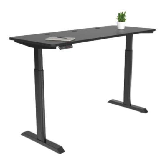
PowerLift Electric Standing Desk
ELE-TB Series
How can we improve our assembly instructions?
Your comments and suggestions are important to us.
Please e-mail us at: engineering@versaproducts.com
American Manufacturing
Protected by US Patent No. 10,485,336 & 10,849,424
Assembly Instructions
Assembly Instructions
Lifetime Warranty
REV. 09142022
MADE IN
AMERICA
1 (800) 465-1660
support@versadesk.com
Advertisement

Related Manuals for versa ELE-TB Series

Summary of Contents for versa ELE-TB Series
- Page 1 Assembly Instructions Assembly Instructions PowerLift Electric Standing Desk REV. 09142022 ELE-TB Series How can we improve our assembly instructions? MADE IN Your comments and suggestions are important to us. AMERICA Please e-mail us at: engineering@versaproducts.com 1 (800) 465-1660 American Manufacturing Lifetime Warranty support@versadesk.com...
- Page 2 Assembly Instructions Tools 4mm Allen wrench Phillips head screwdriver and/or Tape measure (included) hand drill Parts Surface & Frame (Assembly) Feet Control Switch Control Box Power Cord 1 (800) 465-1660 American Manufacturing Lifetime Warranty support@versadesk.com Protected by US Patent No. 10,485,336 & 10,849,424...
- Page 3 Assembly Instructions Hardware 1/4-20 x 1/2” Button 1/4-20 x 3/4” Button 10A x 3/4” Head Screw Head Screw Wood Screw Zip Tie P Clip 1/2-13 Leveler 1 (800) 465-1660 American Manufacturing Lifetime Warranty support@versadesk.com Protected by US Patent No. 10,485,336 & 10,849,424...
- Page 4 Assembly Instructions Place the Leg in between the Frame and align the holes marked in red. Then, use (4) 1/4-20 x 1/2” Button Head Screws to secure the Leg to the Frame as shown. Repeat for other side. Frame 1/4-20 x 1/2 Button Head Screw NOTE: You may need to loosen these screws to be able to properly secure the Leg to the Frame.
- Page 5 Assembly Instructions Attach (2) 1/2-13 Levelers to bottom of the Foot. Repeat for other side. Foot 1/2-13 Leveler Use (2) 10A x 3/4” Wood Screws to attach the Control Switch to the Surface as shown. The surface has 2 pre-drilled holes near the edge to fulfill this step. NOTE: You can also attach the switch on the other end of the...
- Page 6 Assembly Instructions Attach the Control Box to the Surface using (2) 10A x 3/4 Wood Screws. The Control Box has 2 mounting holes that should be used to complete this step. Make sure you place the control box on the side closest to the Control Switch as shown.
- Page 7 Assembly Instructions Control Switch Operation Instruction Display Save Down Memory Standing Memory Sitting Position Position 1. Save Lift up/down the table to the desired height, and press button, the Display will show - while the - keeps flashing, then press button, after which, the height memory is done.