
Related Manuals for Citel LSCM-D

Summary of Contents for Citel LSCM-D
- Page 1 LSCM-D User Manual Smart SPD Monitoring Device Surge Current Counter N210201c - This document could be modified without notice. Update available on website.
- Page 2 France Shanghai · China Head Office Tel: +86 21 5812 2525 Sales department e-mail: info@citelsh.com Sèvres, France Web:www.citel.cn Address:No.88,Shangke Road, Tel: +33 1 42 23 50 23 Zhangjiang Hi-Tech Park, Pudong, e-mail: contact@citel.fr Shanghai, China Web: www.citel.fr...
- Page 3 1-3-1 Technology 1-3-2 Main features 2-1 Main view and mechanical scheme 2-2 Interface introduction 2-2-1 Power supply P7/10 2-2-2 RS485 ports 2-2-3 Sensor Installation 2-2-4 Alarm input 2-2-5 Alarm output 2-2-6 PE shield connection 2-3 Typical wiring diagram for LSCM-D...
- Page 4 3-1 Main operator panel 3-2 Main operator interfaces 3-2-1 First page-basic information P11/17 3-2-2 Second page-switch status 3-2-3 Third page-surge current information OLED Instructions 3-2-4 Fourth page-status information of the content system 3-3 System setting3-3-1 Setting introduction 3-3-2 First page-system settings 3-3-3 Second page-system settings P18/20 4-1 Introduction...
- Page 5 More precise lifetime prediction to ensure timely maintenance for LSCM-D for lightning monitoring surge protection devices (SPDs) More reasonable type selection for SPDs...
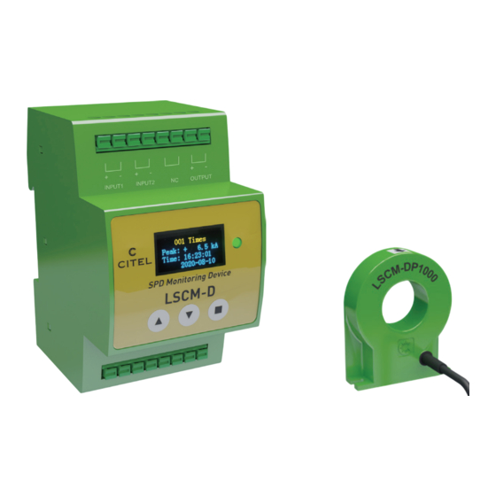
- Page 6 LSCM-D also can be used for monitoring SPD/MCBs/Fuses remote signalling state Output alarm for monitoring input switching and lightning are both applicable. LSCM-D is composed of one sensor and one monitoring unit, detailed combinations described as follwing table. Type Description Version...
- Page 7 1-Introduction 1-2 Main functions The main funcitons for LSCM-D described as below : Lightning and surge current detection for wide detection Two inputs and one output terminal can realize to range : monitor remote/switching signalling from SPDs and its associated disconnectors (operating/disconnected).
- Page 8 Voltage signal Memory:128KB Differential ADC Signal amplifier OLED display module measured by sensor signal acquisition Program burn port USART1 GPIO GPIO Sensor REF signal DC-DC module LED status Key control 24Vdc/230Vac power input Monitoring Unit Fig1. LSCM-D system schematic diagram...
-
Page 9: Main Features
Surge current monitoring With high precision The peak value and polarity of surge currents flowing The precision rate for LSCM-D within +/-5%. The precision conductors, including PE wires or down conductor, as well could reach better performance in certain electromagnetic as the time stamping for the event can be recorded. - Page 10 Based on compact design and wide surge detection range for the recorded information (surge parameters, devices status) • Remote signal communication: remote computer can access to the full recorded data of LSCM-D through RS485 • Detect the surge current via SPD PE wire which always communication/Modbuis protocol.
-
Page 11: Installation
2- Installation 2-1 Main view and mechanical Scheme Monitoring unit LSCM-D Sensor LSCM-P1000 Fig2. Mechanical Scheme for LSCM-D... -
Page 12: Interface Introduction
2-2-1 Power supply The monitoring device should connect to the earthing The applicable voltage for power supply is 12-24 system. By this way, the system immunity for LSCM-D can be Vdc/ac or 120-230Vac (two different versions) increased and the common interference through RS485 can (please refer to 1-3-2). - Page 13 2-Installation 2-2-6 Sensor Connect to SPD remote signal Standby port LSCM-D equipped with dedicated coil sensor for Connect to external alarm equipment Connect to external disconnectors surge measuring : two versions ar available for different detection range. The sensor should be mounted around the discharge conductors as fig4 shows.
- Page 14 2-Installation Disconnection Contactor monitoring 2-3 Typical wiring diagram for LSCM-D Remote contact of external disconnector for SPD • Symmetrical DIN rail mounting SPD remote signal • Connection terminal : spring contact -1.5 mm² wire max AC Power • Operating/storage temperature : -25/+70 °C •...
- Page 15 3-OLED Instructions 3-1 Main operator panel Monitoring unit equipped with one 128×64 OLED display screen and three operating buttons like below, buttons from left to right are defined as”▲▼■"respectively. The main interface for OLED can be divided into four main operator interfaces (3-2) and two system setting interface (3-3).
-
Page 16: Switch Status
3-2 Main operator interfaces CITEL CITEL 3-2-1 First page : basic information SPD Monitoring SPD Monitoring The first interface displays basic information for LSCM-D, including 16:21:40 16:21:40 2020-08-10 2020-08-10 manufacturer name, device designation, real-time clock time and date. 3-2-2 Second page : switch status... - Page 17 3-OLED Instructions 3-2-3 Third page : Surge current information The third page is the interface about surge current information. Press button ■ 001 Times 001 Times can access this page and detailled the recorded detected data (the latest 1200 Peak: + Peak: + 6.5 kA 6.5 kA...
- Page 18 ▲▼ can move the cursor in this page. User address There are two pages for system setting. By using buttons ▲ ▼can modify LSCM-D communication address with upper computer, and use button ■ to confirm • The first page as 3-3-2 described, RS485 baud rate code setting.
- Page 19 3-OLED Instructions Output state related to remote signalling and associated device Language setup Four states can be defined in sub-option as below: Setting language, select buttons ▲ and ▼ can modify -Input 1 =>after set and when state for input 1 changes, the the optional language for English and simplified state of output will change 1.0 s and then back to normal Chinese, and use button ■...
- Page 20 3-OLED Instructions 3-3-3 Second page : System settings Output state related to lightning strikes Time setup Two states can be defined in sub-option as below: After access the second system setting page, press button ■ -Open the output related for lightning detection=> when to enter the year setting, and select buttons▲and▼...
- Page 21 After select the sensor, the lightning detection range also can been Be careful, if the record is cleared, all the data can not set too, take LSCM-D/24/P1000 for example, three option recovered. "1kA-100kA", "2kA-100kA" and "4kA-100kA" optional, the range When all setting finished, move the cursor to “exit setup”...
-
Page 22: Modbus Protocol
4- Modbus Protocol 4-1 Introduction 4-1-1 About Modbus protocol Modbus is a very commonly used communication protocol and and with it, control equipment produced by different manufac- communication convention in industry. Modbus protocol turers can be connected into an industrial network for central- includes RTU, ASCII and TCP type, and Modbus-RTU is the ized monitoring. - Page 23 field. The response supported by almost every commercial SCADA, HMI, OPC Server message from LSCM-D also consists of the Modbus and data acquisition software program in the marketplace. This protocol, including the domain to confirm the action, any makes it very easy to integrate Modbus compatible equipment into data to return, and an error detection domain.
- Page 24 first in low bytes and then in high bytes, therefore, the high byte record, verify the program in the slave device, etc. of CRC is the last byte to send a message. 《Modbus protocol》for LSCM-D to programe please visit CITEL official website and download it.
Need help?
Do you have a question about the LSCM-D and is the answer not in the manual?
Questions and answers