
Related Manuals for Citel LSCM-D

Summary of Contents for Citel LSCM-D
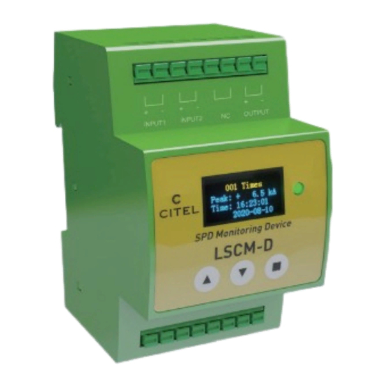
- Page 1 LSCM-D User Manual Smart SPD Monitoring Device Surge Current Counter N210201 - This document could be modified without notice. Update available on website.
- Page 2 France Shanghai · China Head Office Tel: +86 21 5812 2525 Sales department e-mail: info@citelsh.com Sèvres, France Web:www.citel.cn Address:No.88,Shangke Road, Tel: +33 1 42 23 50 23 Zhangjiang Hi-Tech Park, Pudong, e-mail: contact@citel.fr Shanghai, China Web: www.citel.fr...
- Page 3 1-3 Technology and features Introduction 1-3-1 Technology 1-3-2 Main features 2-1 Mechanical scheme 2-2 Interface introduction 2-2-1 Power supply P7/10 2-2-2 RS485 ports 2-2-3 Sensor Installation 2-2-4 Alarm input 2-2-5 Alarm output 2-2-6 PE shield connection 2-3 Typical wiring diagram for LSCM-D...
- Page 4 3-1 Main operator panel 3-2 Main operator interfaces 3-2-1 First page-basic information P11/17 3-2-2 Second page-switch status 3-2-3 Third page-surge current information OLED Instructions 3-2-4 Fourth page-status information of the content system 3-3 System setting3-3-1 Setting introduction 3-3-2 First page-system settings 3-3-3 Second page-system settings P18/29 4-1 Introduction...
- Page 5 1 - Introduction 1-1 Overview: LSCM-D As we know, surge voltages caused by lightning strikes can lead to severe damages and destructions to power and signaling networks, such as common buildings, new energy plant structures like wind turbines. SPDs (Surge Protective Devices) are currently used to tackle this important threat.
- Page 6 The Solution : The smart monitoring and measuring device LSCM-D is designed for measuring the surge current which will flow in the Surge protection branch and for indicating the the status of the SPD and and its associated disconnectors .
- Page 7 1-Introduction 1-2 Main functions The main funcitons for LSCM-D described as below : Lightning and surge current detection for wide detection Monitor connected devices: with two inputs and one range : output switch signal, the status of SPD and/or backup - 0.3/25kA@10/350 s or 0.3/50kA @ 8/20 s(LSCM-P300)
- Page 8 Differential ADC Signal amplifier OLED display module measured by sensor signal acquisition Internal SRAM: packaging Program burn port USART1 GPIO GPIO Sensor REF signal DC-DC module LED status Key control 24Vdc/230Vac power input Monitoring Unit Fig1. LSCM-D system schematic diagram...
-
Page 9: Main Features
1-Introduction 1-3-2 Main features With high precision The accuracy rate for LSCM-D can declare within +/-5%. The Surge current detection precision could reach better performance in low electromag- The peak value and polarity of surge currents flowing netic interference conditions. - Page 10 • Local information: the front OLED display gives access Based on the compact design and wide surge detection the recorded information (surge parameters, devices status) range for 10/350 s and 8/20 s, LSCM-D typically can be • Remote signal communication: a remote computer, used for: through RS485 communication/Modbuis protocol to the •...
-
Page 11: Installation
2- Installation 2-1 Mechanical scheme Monitoring unit LSCM-D Sensor LSCM-P1000 Fig2. Mechanical scheme for LSCM-D... -
Page 12: Interface Introduction
2-2-1 Power supply 2-2-3 Sensor The applicable voltage for power supply is 12-24 LSCM-D equipped with dedicated coil sensor for surge measuring : two Vdc/ac or 120-230Vac (two different versions) versions ar available for different detection range. The sensor should be (please refer to 1-3-2). - Page 13 Connect to external alarm equipment Connect to external disconnectors earthing system with each one of the two SH ports (Shield) . By this way, the system immu- nity for LSCM-D can be increased and the common interference through RS485 can be INPUT1 INPUT2...
- Page 14 2-Installation Disconnection Contactor monitoring 2-3 Typical wiring diagram for LSCM-D Remote contact of external disconnector for SPD • Symmetrical DIN rail mounting SPD remote signal • Connection terminal : spring contact -1.5 mm² wire max AC Power • Operating/storage temperature : -25/+70 °C •...
- Page 15 3-OLED Instructions 3-1 Main operator panel Monitoring unit equipped with one 128×64 OLED display screen and three operating buttons like below, buttons from left to right are defined as”▲▼■"respectively. The main interface for OLED can be divided into four main operator interfaces (3-2) and two system setting interface (3-3).
-
Page 16: Switch Status
3-2 Main operator interfaces CITEL CITEL 3-2-1 First page : basic information SPD Monitoring SPD Monitoring The first interface displays basic information for LSCM-D, including 16:21:40 16:21:40 2020-08-10 2020-08-10 manufacturer name, device designation, real-time clock time and date. 3-2-2 Second page : switch status The second page displays disconnectors’... - Page 17 3-OLED Instructions 3-2-3 Third page : Surge current information The third page is the interface about surge current information. Press button ■ 001 Times 001 Times can access this page and detailled the recorded detected data (the latest 1200 Peak: + Peak: + 6.5 kA 6.5 kA...
- Page 18 3-OLED Instructions 3-3 System settings 3-3-1 Settings introduction System setup is mainly used to set up system information, such as RS485 communication baud rate, user device address, languages settings. Press the function button ■ more than 5 seconds can access the first system settings page, press button ▲▼ can move the cursor in this page.
- Page 19 ■ to confirm the change. User address If continue to press ▼, the second page for system By using buttons ▲ ▼can modify LSCM-D communication address settings as 3-2-3 will display. with upper computer, and use button ■ to confirm code setting.
- Page 20 After select the sensor, the lightning detection range also can been can be set by the means of time synchronization set too, take LSCM-D/24/P1000 for example, three option "1kA-100- with upper computer, more simpleand fast than kA", "2kA-100kA" and "4kA-100kA" optional, the range option the button way.
- Page 21 3-OLED Instructions Clear record If user want to clear all history record, first move the cursor to “clear record” option, then press button ■ to confirm the selec- tion. Be careful, if the record is cleared, all the data can not recovered. When all setting finished, move the cursor to “exit setup”...
-
Page 22: Modbus Protocol
4- Modbus Protocol 4-1 Introduction 4-1-1 About Modbus protocol and with it, control equipment produced by different manufac- Modbus is a very commonly used communication protocol and turers can be connected into an industrial network for central- communication convention in industry. Modbus protocol ized monitoring. - Page 23 field. The response supported by almost every commercial SCADA, HMI, OPC Server message from LSCM-D also consists of the Modbus and data acquisition software program in the marketplace. This protocol, including the domain to confirm the action, any makes it very easy to integrate Modbus compatible equipment into data to return, and an error detection domain.
- Page 24 4-Modbus Protocol Device address Data field RTU mode address field of a message frame contains eight Data field is composed of two sets of hexadecimal numbers, with bits. The possible address from the device is 0...247 (decimal), a range of 00...FF. A pair of an RTU character sent from the and the address range of a single device is 1...247.
-
Page 25: Read Device Information
4-Modbus Protocol 4-2 Read device information 4-2-1 Read the status of input/output ports Query Response Slave address Slave address Function Function Starting address Hi Byte count Starting address Lo Data Hi No. register number Hi xx(1) Data Lo No. register number Lo CRC check Lo CRC check Lo CRC check Hi... - Page 26 4-Modbus Protocol 4-2-2 Read device time Query Response Slave address Slave address inute Function Function Second Starting address Hi Byte count Covering position Starting address Lo Year Hi CRC check Lo No. register number Hi Year Lo CRC check Hi No.
- Page 27 4-Modbus Protocol 4-2-3 Read the total times of lightning trigger and input ports trigger Query Response Slave address Input 2 port total number Lo Slave address Function CRC check Lo Function Byte count CRC check Hi Starting address Hi Lightning strike times Hi Starting address Lo Lightning strike times Lo No.
- Page 28 4-Modbus Protocol 4-2-4 Read lightning strike record information Query Response Slave address Month Slave address Function Date Function Byte count Hour Starting address Hi Nth lightning strikes Hi Minute Starting address Lo Nth lightning strikes Lo Second xx(1) No. register number Hi xx(2) Peak current integer part Polarity...
- Page 29 4-Modbus Protocol 4-2-5 Read the input port record Query Response Slave address Slave address Month Function Function Date Starting address Hi Byte count Hour xx(1) Starting address Lo Data 1 Hi Minute xx(2) No. register number Hi Trigger times Hi Second No.
- Page 30 4-Modbus Protocol 4-2-6 Read language, sensor model and device serial number Query Response Slave address Slave address xx(1) Function Function Language xx(2) Starting address Hi Bytes count Sensor tarting address Lo None No. register number Hi None No. register number Lo None CRC check Lo None...
- Page 31 4-Modbus Protocol 4-3 Write device information 4-3-1 Write output state Query Response xx(1) Slave address Data Lo Slave address Function CRC check Lo Function Starting address Hi CRC check Hi Starting address Hi Starting address Lo Starting address Lo No. register number Hi No.
- Page 32 4-Modbus Protocol 4-3-2 Write the time in device Query Response Slave address Month Slave address Function Date Function Starting address Hi Hour Starting address Hi Starting address Lo Minute Starting address Lo No. register number Hi Second No. register number Hi No.
-
Page 33: System Restart
4-Modbus Protocol 4-3-3 System restart Slave address Byte count Function Data Hi Starting address Hi Data Lo Starting address Lo CRC check Lo No. register number Hi CRC check Hi No. register number Lo... - Page 34 4-Modbus Protocol...
Need help?
Do you have a question about the LSCM-D and is the answer not in the manual?
Questions and answers