Table of Contents
Advertisement
These instructions apply to the 800 series Smart Thermostat Zoning system only.
The EcoNet® Zoning System allows a single HVAC system the ability to maintain multiple desired space
temperatures by managing capacity and airflows into different spaces in the home. While zoning is not a
new concept, the equipment, how it operates, smart communications as well as changes to regulations
may be. The EcoNet zoning system operates on different specific principals than many other zoning
systems on the market today.
Only EcoNet® compatible HVAC equipment can be used. With limited exception, non-communicating, two
stage outdoor units may be used but are limited to two zones. Ideal applications will use fully modulating
equipment where there is more flexibility in system minimum airflow requirements, and those ideal
applications will not generally need an Intelligent Bypass. To achieve this, regardless of equipment used,
each of the individual zones should support the minimum airflow of the equipment selected and installed.
Do not depend on Overconditioning or an Intelligent Bypass for large volumes of excess air as this may
create system issues and customer complaints.
A Successful and satisfactory installation will start with a full understanding of the EcoNet Zoning System's
capabilities, features and limitations as well as the skills and training of the installation crew. For best
results...
Attend up to date EcoNet Zoning training provided by a qualified Distributor
Partner or a Factory District Technical Representative
Read and Understand the EcoNet 800 Series Application and Design Guide.
Read and commit to following these Installation Instructions to insure a
pleasing experience for your customer.
Page | 1
EcoNet ® 800 Series Zoning
Installation Instructions
.
Advertisement
Table of Contents

Subscribe to Our Youtube Channel
Related Manuals for EcoNet Zoning 800 Series


Summary of Contents for EcoNet Zoning 800 Series
- Page 1 These instructions apply to the 800 series Smart Thermostat Zoning system only. The EcoNet® Zoning System allows a single HVAC system the ability to maintain multiple desired space temperatures by managing capacity and airflows into different spaces in the home. While zoning is not a new concept, the equipment, how it operates, smart communications as well as changes to regulations may be.
-
Page 2: Table Of Contents
Damper Selection Installing the Zone Panel(s) Installing the Dampers Wiring Overview The EcoNet Bus Wiring the Thermostats Wiring the Zone Panel & Dampers 16 Setting the Dip Switches Intelligent Bypass Adding a Transformer Start up and Commissioning Pages 19-26 ... -
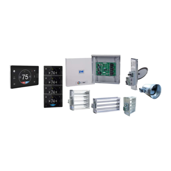
Page 3: Equipment And Components Pages
Many EcoNet-enabled HVAC systems with ECM variable speed (constant CFM) blower motors are supported. EcoNet systems with a constant torque (X-13 or similar) blower motor or gas furnaces with only one stage of heat are NOT supported (E.G. RH2TZ series air handlers or (-)801V Gas Furnaces). -
Page 4: Components
These controls do not necessarily have to be wired back to the EcoNet zoning panel or main control, but rather they can be wired in series to any device on the EcoNet communicating bus. The zone controls look and are physically identical to the main (-)ETST800SYS Smart Thermostat but have very different control firmware. - Page 5 EWC® Brand Ultra Zone® – Fully Modulating Dampers The EcoNet Zoning System is compatible only with EWC® Ultra-Zone® damper models URD (ducted round), ND (rectangular louvered), or SID (slip-in round). They are all 24VAC power open/power close allowing for full modulation to one of 35 positions. The dampers are wired to the zone panel, with each zone being able to support up to five (5) dampers.
-
Page 6: Dampers
A bypass damper will connect to the EcoNet zone panel in either the Zone 3 location when on a two- zone system or for systems with 3-5 zones, it will be connected to the Zone 6 location on the second zone panel. -
Page 7: Air Handler Sensors
47-24225-01 Furnace Supply Air Sensor Air Handler Sensors The RXHT-A02 Sensor kit is used for air handlers and includes two sensors. While these sensors are compatible with the last generation of equipment and come with 2 or 3 prong connectors, the connectors will need to be cut off, and the wires stripped at the end to be used in current equipment. -
Page 8: Zoning Considerations Pages
Unlike some off the shelf zoning systems, the EcoNet system is not only tasked with providing the best comfort but it also must protect the equipment. At face value, the simple solution may be to install a bypass but... -
Page 9: Designing The Zones
Zoning Considerations continued Ideally, the modulating zoning system, essentially a variable duct system, should use fully modulating equipment. This would include the modulating gas furnaces and the 18 SEER2 inverter systems. These systems work better than others in a zoning application. It cannot be stressed enough that managing expectations is a big part of preventing problems or concerns after the system is installed. - Page 10 According to the tables beginning on page 30, the furnace minimum airflow when running on low fire is 1475 but it can be adjusted to as low as 1162 using the installer set up screen in the EcoNet thermostat. When running in cooling mode, the minimum airflow is 580 CFM and if a 10% airflow reduction is applied in the installer settings, that will now be 464 CFM.
-
Page 11: Damper Selection
600 in heat mode. If those are adjusted down by 10% in the thermostat, they can now be 450 and 495 respectively. (The 3, 4 and 5 ton heat pumps, when zoned by the EcoNet zoning systems are reduced to these values). The thermostat and zoning system control the outdoor unit’s capacity and the air handler does what the outdoor unit tells it to, except when the electric heat is on as auxiliary or supplemental heat. -
Page 12: Installing The Zone Panel(S)
Installing the Zone Panel(s) The zone panels are to be installed on a wall or studs adjacent to the indoor air handler or furnace. Plywood will make a good backing board if needed. They should not be installed directly to the equipment or supply duct. -
Page 13: Wiring Overview
Wiring Overview The EcoNet zoning system communicates on a 4-wire bus between all equipment, zone panels and thermostats. The 4 wires and terminals are all designated as E1, E2, R and C. The E1 and E2 is where the communication takes place. -
Page 14: The Econet Bus
The EcoNet Bus The EcoNet bus is connected to the top left of the zone panel using the designations E1, E2, R and C. The other terminals along the left side of the panel are unused in all applications. The zone dampers are connected along the right side of the board and are designated as Z1/4, Z2/5 and Z3/6. -
Page 15: Wiring The Thermostats
Wiring the Thermostats The main thermostat and zone controls have the same subbase. The subbase has 6 terminals marked R – 24vac, C – Common, S1 – Remote Sensor, S2 – Remote Sensor, E1 – Communication, E2 – Communication. These connections and wires must be the same at all devices. S1 and S2 can be used to install a remote space temperature sensor if desired. -
Page 16: Setting The Dip Switches
6 an actual zone or otherwise unused but has no bypass. Intelligent Bypass The Intelligent Bypass is one of the EcoNet zoning system’s method to shed excess air when a zone has a maximum airflow setting slightly lower than the minimum airflow required to allow the system to run. - Page 17 used in this case to allow 100 CFM from the supply plenum to be bypassed, most commonly, back into the return plenum by opening a damper that is mounted in a duct between the two. The intelligent bypass considers demand at other zones as well. If another zone has a small demand and the damper to that zone is enough to manage that 100 CFM, the bypass would remain closed until the demand changes enough to require it be opened again.
-
Page 18: Adding A Transformer
The primary voltage to the second transformer may come from the incoming power to the furnace or air handler without issue. In the images above, note the red 24vac wire from the EcoNet bus (thermostats and equipment) is not connected to the zone panel but the common remains connected. This... -
Page 19: Start Up And Commissioning Pages
EcoNet bus, that is the common wire on the second transformer. Start-up and Commissioning If you have been installing EcoNet zoning in the past using the (-)ETST700SYS thermostat, there are quite a few changes in the 800 series that you must pay close attention to. -
Page 20: Naming The Zones
Zone 1 control. This routine will be used to determine the zones basic airflow and provide insight to the proportions between the zones. Don’t get too hung up on the percentages, especially if a bypass is installed. These numbers are used by the EcoNet system’s formulas. Page | 20... - Page 21 Once this value is set, The EcoNet Zone system will record the all open system static value. IN about 1 minute, all zones except zone 1 will close.
-
Page 22: Linearization
the airflow used was lower than full capacity air volume. Each zone tested will appear as “Zone X Size/SP” this static in all cases should be higher than the full open static pressure because some dampers were closed at this time. Finally, a full closed SP will be listed as a result of the portion of the test where all dampers are closed. -
Page 23: Adjusting Airflow Limits
Adjusting Airflow Limits Airflow limits are set to adjust the maximum airflow values for each zone. These limits are meant to allow the installer, along with the homeowner, to control the airflow noise in each zone and to prevent the blower from cutting back and declaring a fault due to high static or blower motor RPM. -
Page 24: Damper Test
or add a bypass at this point, you will have to repeat the duct measurement routine. You do not have to Linearize the dampers again unless you add or change dampers. Do not skip this step! Failure to adjust the airflow limits will most certainly result in a call- back to the job due to noise or faults associated. - Page 25 Humidity Sensor to Use: For humidification and dehumidification, you may select which zone control’s humidity sensor will be used. Selections are to use any desired zone or Average All zones. Overconditioning: Overconditioning on this screen of the main thermostat only sets the value for Zone 1. To set other zones, go to each zone controls settings screen, and unless yes is selected under All Zones follow Zone 1.
-
Page 26: Diagnostics And Troubleshooting Pages
You may also select specific equipment to find other useful information to help you diagnose issues and be better equipped to install and adjust the EcoNet zoning system. These pages are constantly being updated. Bookmark, or add to favorites the EcoNet help pages for future use. - Page 27 if there was communication with a panel established and has since gone away. Check wiring to respective zone panel A001_Z through A006_Z: Zone Control Room Sensor Fault The room temperature sensor in the respective zone control has failed. If it’s a remote sensor, replace the remote sensor.
-
Page 28: Led Lights On Panel
T024_Z: Supply Air Sensor Fault for Bypass If the Zoning system is configured for a bypass, the EcoNet system expects to see a supply air sensor for the furnace or air handler. All systems with bypass are required to have a supply air sensor. -
Page 29: Customer App
LED Locations Bottom Left: This LED is not used by the EcoNet Zoning system. It may be on or off. Upper Center: These two LED’s Indicate that the board has power and will blink in what appears to be a random sequence when either transmitting or receiving data from the EcoNet system. - Page 30 point of contact. The DSC is factory trained and has access to the factory District Technical Representatives (DTR) and Product Support Specialists (PSS) who are well versed in all the products. When calling for help, its only practical to call from the job site where you can get information needed by the DSC.
-
Page 31: Minimum Airflow Tables Pages
Minimum Airflow Requirements The tables below on pages 30-32 show minimum airflows for design and application of the zoning system. Note your selected outdoor unit, indoor unit and if it applies your electric heat selection. The minimum airflow for design will be the highest of the components used. Review the components in your system minimum airflows and use the highest to determine your smallest zone capability. - Page 32 Furnaces w/ Non-Communicating 2 Stage OD Low Cool or Heat Pump Mode. Model OD Unit Size Modulating (-)98MV (-)98MV0603A17 (-)98MV0703A17 (-)98MV0855A21 1050 1313 (-)98MV1005A21 1050 1313 (-)98MV1155A24 1050 1313 Model OD Unit Size Modulating (-)97MV (-)97MV0603A17 (-)97MV0703A17 (-)97MV0855A21 1050 1313 (-)97MV1005A21 1050 1313...
- Page 33 Outdoor Units Model Low Cool Low Cool-10% Low Heat Low Heat – 10% High Tier AC (-)A18AZ24 (-)A18AZ36 (-)A18AZ48 (-)A18AZ60 Model Low Cool Low Cool-10% Low Heat Low Heat – 10% High Tier HP (-)P18AZ24 (-)P18AZ36 550¹ 495¹ (-)P18AZ48 600² 540²...
-
Page 34: Zoning Job Site Information Sheet Pages
EcoNet Zoning Job Site Information Sheet Page1 Page | 34... - Page 35 EcoNet Zoning Job Site Information Sheet Page2 An electronic PDF version of the Zoning JSIS can be found in PTS. Page | 35...
Need help?
Do you have a question about the Zoning 800 Series and is the answer not in the manual?
Questions and answers