
Related Manuals for Quantifi Photonics OSA 1000 Series


Summary of Contents for Quantifi Photonics OSA 1000 Series
- Page 1 1000 Series Optical Spectrum Analyzer MATRIQ User Manual quantifiphotonics.com...
- Page 2 Information provided by Quantifi Photonics is believed to be accurate and reliable. However, no responsibility is assumed by Quantifi Photonics for its use nor for any infringements of patents or other rights of third parties that may result from its use. No license is granted by implication or otherwise under any patent rights of Quantifi Photonics.
-
Page 3: Table Of Contents
7.4 Manage CohesionUI settings 7.5 Change the instrument IP address 7.6 View system information 8 Controlling your OSA with CohesionUI 8.1 OSA sweep settings 3 / 82 Quantifi Photonics | OSA 1000 Series MATRIQ User Manual | Document version 3.02... - Page 4 9.5.1 Common commands 9.5.2 Slot commands 9.5.3 Configuration Commands 9.6 Programming examples 9.7 SCPI Command Console 10 Programming examples and applications 10.1 Setting up NI-MAX application 4 / 82 Quantifi Photonics | OSA 1000 Series MATRIQ User Manual | Document version 3.02...
- Page 5 14.1 Contacting the Technical Support Group 14.2 Transportation 15 Warranty Information 15.1 General information 15.2 Liability 15.3 Exclusions 15.4 Certification 15.5 Service and repairs 5 / 82 Quantifi Photonics | OSA 1000 Series MATRIQ User Manual | Document version 3.02...
-
Page 6: What's In This User Manual
Controlling your OSA with CohesionUI SCPI commands: Controlling your OSA with SCPI commands Programming examples and applications Maintenance Upgrade firmware Restore factory settings 6 / 82 Quantifi Photonics | OSA 1000 Series MATRIQ User Manual | Document version 3.02... -
Page 7: Conventions
Indicates a potentially hazardous situation which, if not avoided, may result in minor or moderate injury or component damage. Do not proceed unless the required conditions are met and understood. NOTE Indicates relevant information that requires your attention. 7 / 82 Quantifi Photonics | OSA 1000 Series MATRIQ User Manual | Document version 3.02... -
Page 8: Safety Information
Do not install or terminate fibers while the light source is active. Turn the Quantifi Photonics product OFF before inspecting the end face(s) of the product, or any optical patch cords connected to it. Never look directly into a live fiber; ensure that your eyes are protected at all times. -
Page 9: Electrostatic Discharge Precautions
Store the unused product in the original protective electrostatic packaging that it was shipped in. Use a wrist strap and grounding table mat when unpacking or handling the product. 9 / 82 Quantifi Photonics | OSA 1000 Series MATRIQ User Manual | Document version 3.02... -
Page 10: Introducing The Osa 1000 Series
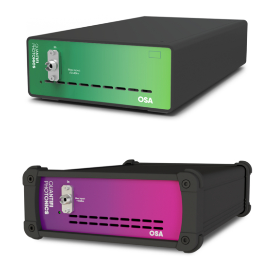
4 Introducing the OSA 1000 Series The OSA 1000 Series enables cost-effective spectral test and measurement in a compact form factor. The OSA is grating-based and is designed for efficient, space saving performance where space and time are critical. It is an excellent fit for fully automated production testing of optical sources, amplifiers, transceivers, and passive optical components. -
Page 11: Hardware Description
On / Off push button 4.2 Status LEDs The LED shows the status of the channel: Meaning Product is powered OFF Product is powered ON solid GREEN 11 / 82 Quantifi Photonics | OSA 1000 Series MATRIQ User Manual | Document version 3.02... -
Page 12: Setting Up Hardware
Always clean optical end faces before mating. NOTE You must use the external power supply that has been supplied by Quantifi Photonics with the unit. Any attempt to use a different external power supply may cause product damage and will void your warranty. ... -
Page 13: Set Up Your Osa 1000 Series Product And Power On
If a query is sent to the OSA before initialization has successfully completed, it will return an array of zeroes (0). 13 / 82 Quantifi Photonics | OSA 1000 Series MATRIQ User Manual | Document version 3.02... -
Page 14: Instrument Ip Address
You can change the instrument's static USB IP address and you can assign a static Ethernet IP address using CohesionUI. Multi-instrument control If you have several Quantifi Photonics instruments with static IP addresses on your network, make sure to assign a unique IP address to each instrument before connecting. -
Page 15: Installing Software
6 Installing software To work with Quantifi Photonics MATRIQ and EPIQ instruments, you need to install the latest version of the Cohesion Operator software package on any computer that you use to connect with your instrument (client computer). The software package is included on the USB media device that we provide with your instrument, or you can download it from quantifiphotonics.com (go to Resources >... -
Page 16: Install The Cohesion Operator Software Package
The installation wizard will install required drivers, applications, and desktop icons on the computer. Multi-instrument control If another Quantifi Photonics instrument is already connected to the client computer via USB, make sure each instrument has a unique USB IP address to avoid any addressing conflicts. -
Page 17: Check Firmware Version And Other Information
To check details in Cohesion Operator: 1. Select the instrument. 2. Click Connect. 3. Current instrument information will be displayed. Installed Package refers to the currently loaded firmware version. 17 / 82 Quantifi Photonics | OSA 1000 Series MATRIQ User Manual | Document version 3.02... -
Page 18: Upgrade Firmware
The instrument will be upgraded to the selected firmware package. This can take a few minutes and the instrument might reboot several times in the process. 7. A message shows when the upgrade is complete. 18 / 82 Quantifi Photonics | OSA 1000 Series MATRIQ User Manual | Document version 3.02... - Page 19 If an upgrade attempt is unsuccessful, the Cohesion Operator will stop the upgrade process and restore the instrument to its previous firmware version. Messages will be displayed accordingly. 19 / 82 Quantifi Photonics | OSA 1000 Series MATRIQ User Manual | Document version 3.02...
-
Page 20: Restore Factory Settings
This will retrieve instrument information, with Installed Package showing the current firmware version. 4. Click Restore. The instrument will be returned to factory settings, including IP address settings. 20 / 82 Quantifi Photonics | OSA 1000 Series MATRIQ User Manual | Document version 3.02... -
Page 21: Cohesionui - Overview
7 CohesionUI - Overview CohesionUI is a web-based graphical interface that you can use to work with your Quantifi Photonics product. CohesionUI is part of the MATRIQ firmware package running on your Quantifi Photonics instrument. From the menu on the left you can navigate to the following pages: 1. -
Page 22: Access Instruments With Cohesionui
2. Select the instrument by entering its IP address or by selecting it from the Discovery dropdown. 3. Click Open CohesionUI. CohesionUI will open in your standard browser. 22 / 82 Quantifi Photonics | OSA 1000 Series MATRIQ User Manual | Document version 3.02... - Page 23 To open CohesionUI in a browser: 1. Launch a supported browser. 2. Enter the instrument IP address in the address bar. CohesionUI will launch in the browser. 23 / 82 Quantifi Photonics | OSA 1000 Series MATRIQ User Manual | Document version 3.02...
-
Page 24: Set Values
4. Click on a parameter and select a value from the dropdown menu. 5. Confirm the value. For details on how to change the step size, refer to Manage CohesionUI settings. 24 / 82 Quantifi Photonics | OSA 1000 Series MATRIQ User Manual | Document version 3.02... -
Page 25: Set Values And Actual Values
: The actual value of the parameter as queried by the product. SET: The intended value of a given parameter as set by the user. 25 / 82 Quantifi Photonics | OSA 1000 Series MATRIQ User Manual | Document version 3.02... -
Page 26: Manage Cohesionui Settings
Please note that the units displayed on this page are not always relevant for each product. 3. Step size refers to the amount by which a value is increased or decreased when clicking the + or - button. 26 / 82 Quantifi Photonics | OSA 1000 Series MATRIQ User Manual | Document version 3.02... - Page 27 To adjust unit preferences one at a time: 1. Hover over SETTINGS. 2. Select a unit from the dropdown, for example the power unit. 27 / 82 Quantifi Photonics | OSA 1000 Series MATRIQ User Manual | Document version 3.02...
-
Page 28: Change The Instrument Ip Address
You can change the instrument's static USB IP address, and assign a static Ethernet IP address if required. Multi-instrument control If you have several Quantifi Photonics instruments with static IP addresses on your network, make sure to assign a unique IP address to each instrument before connecting. - Page 29 To change the Ethernet IP address: 1. Connect with the instrument from a client computer via USB. Ensure that this the only Quantifi Photonics instrument currently connected via USB. 2. Open CohesionUI using the currently assigned USB IP address. 3. Go to SETTINGS.
-
Page 30: View System Information
2. For more details, click INFO to display the information panel. 3. The information panel lists the instrument's serial number, and software and firmware versions. 30 / 82 Quantifi Photonics | OSA 1000 Series MATRIQ User Manual | Document version 3.02... -
Page 31: Controlling Your Osa With Cohesionui
8 Controlling your OSA with CohesionUI You can use Quantifi Photonics' graphical user interface CohesionUI to work with your OSA instrument. For details on how to get started with CohesionUI, refer to CohesionUI - Overview. In CohesionUI you can control: 1. OSA sweep settings 2. -
Page 32: Osa Sweep Settings
After setting the START and STOP frequency / wavelength values and the number of sweep POINTS, clicking APPLY will save the parameter values into memory and update the sweep settings of the OSA. 32 / 82 Quantifi Photonics | OSA 1000 Series MATRIQ User Manual | Document version 3.02... - Page 33 This second panel has two draggable bars at either end of the frequency / wavelength span, which can be moved to zoom the main trace view to a specific range. Zooming does not change the actual START and STOP frequency / wavelength sweep values; it only changes the displayed trace. 33 / 82 Quantifi Photonics | OSA 1000 Series MATRIQ User Manual | Document version 3.02...
- Page 34 The MIN and MAX values are limited by the START and STOP values that were set in the SWEEP settings. The OSA cannot zoom the display to a value outside the START / STOP range. 34 / 82 Quantifi Photonics | OSA 1000 Series MATRIQ User Manual | Document version 3.02...
-
Page 35: Osa Analysis Settings
If MASK AREA (GHz) = NOISE AREA (GHz), the OSA will use the entire NOISE AREA (GHz) for noise calculations. If set MASK AREA (GHz) > NOISE AREA (GHz), the OSA will decrease the MASK AREA (GHz) to equal the NOISE AREA (GHz). 35 / 82 Quantifi Photonics | OSA 1000 Series MATRIQ User Manual | Document version 3.02... - Page 36 Channel power at SIGNAL RBW (nm). CHANNEL LEVEL (dBm) = LEVEL (dBm) – NOISE (dBm/NBW) SNR (dB) Optical signal to noise ratio SNR=CHANNEL LEVEL (dBm)-NOISE (dBm/NBW) 36 / 82 Quantifi Photonics | OSA 1000 Series MATRIQ User Manual | Document version 3.02...
- Page 37 37 / 82 Quantifi Photonics | OSA 1000 Series MATRIQ User Manual | Document version 3.02...
- Page 38 Apply the parameters by toggling the ENABLE/DISABLE button to ENABLE. Detected peaks will be highlighted in the trace, measurements will be displayed in the table below the trace. 38 / 82 Quantifi Photonics | OSA 1000 Series MATRIQ User Manual | Document version 3.02...
-
Page 39: Smsr
HIGHEST ADJACENT PEAK and HIGHEST PEAKS ON EITHER SIDE OF MASK methods. After all parameters have been set, toggle the ENABLE / DISABLE button to apply the changes. 39 / 82 Quantifi Photonics | OSA 1000 Series MATRIQ User Manual | Document version 3.02... - Page 40 In the example below, the mask has been set to be 400 GHz either side of the primary peak at approximately 193.415 THz (as shown in the CENTER FREQUENCY). The NOISE THRESHOLD has also been moved down to -60 dBm, to facilitate valid peak detection. 40 / 82 Quantifi Photonics | OSA 1000 Series MATRIQ User Manual | Document version 3.02...
- Page 41 In the example below, the laser has a secondary peak within the primary mode, at approximately 193.362 THz. This could be a valid side mode that exists very close to the primary mode but could have been missed with a masking method. 41 / 82 Quantifi Photonics | OSA 1000 Series MATRIQ User Manual | Document version 3.02...
- Page 42 In the example below, it detects and calculates the SMSR between the primary peak and the two detected peaks at approximately 193.109 THz and 193.719 THz. 42 / 82 Quantifi Photonics | OSA 1000 Series MATRIQ User Manual | Document version 3.02...
- Page 43 A non-symmetric mask can also be applied with this SMSR method, to facilitate SMSR calculation between other side modes. In the example below, the SMSR is calculated between the peaks at approximately 193.109 THz and 194.030 THz. 43 / 82 Quantifi Photonics | OSA 1000 Series MATRIQ User Manual | Document version 3.02...
- Page 44 This detection mode for SMSR calculation will find the primary peak of highest power. It will then detect the highest peaks on either side of this primary peak that are also above the set NOISE THRESHOLD. 44 / 82 Quantifi Photonics | OSA 1000 Series MATRIQ User Manual | Document version 3.02...
-
Page 45: Spectral Width
To calculate the SPECTRAL WIDTH, toggle the ENABLE / DISABLE button. 45 / 82 Quantifi Photonics | OSA 1000 Series MATRIQ User Manual | Document version 3.02... -
Page 46: Find Peaks
If the THRESHOLD is set close to the noise floor of the OSA, more peaks will be detected and displayed. To calculate and display the peaks, toggle the ENABLE / DISABLE button. 46 / 82 Quantifi Photonics | OSA 1000 Series MATRIQ User Manual | Document version 3.02... -
Page 47: Controlling Your Osa With Scpi Commands
[VALUE1] or [VALUE2] can be used, but not both. Some commands may have more than two choices available. This parameter can be omitted where the command has a default defined in the command description. 47 / 82 Quantifi Photonics | OSA 1000 Series MATRIQ User Manual | Document version 3.02... -
Page 48: Index Addressing Of Modules (Slot, Source) And Units (Channel)
Unless specified, all output response data is transmitted in ASCII format. 9.3 Status and event registers 9.3.1 Standard Event Status Register The Standard Event Status Register (SESR) is modified by the Quantifi Photonics product with the results of the command operations. Description 7 (MSB), 6... -
Page 49: Status Byte Register
The Event Status Bit (ESB) is set from the SESR and the SESR Mask Message Available (MAV) is set when there is data in the output queue 3, 2, 1, 0 (LSB) Not used 49 / 82 Quantifi Photonics | OSA 1000 Series MATRIQ User Manual | Document version 3.02... -
Page 50: Status And Event Registers Diagram
9.3.5 Status and event registers diagram 50 / 82 Quantifi Photonics | OSA 1000 Series MATRIQ User Manual | Document version 3.02... -
Page 51: Command Summary
Reset the module to default power-on settings >> :OPTions? Query installed modules >> :IDN? Query the module identification :CHANnel<m> >> :TEMPerature? Query the module temperature 51 / 82 Quantifi Photonics | OSA 1000 Series MATRIQ User Manual | Document version 3.02... -
Page 52: Configuration Commands
Query the SMSR measurement of a sweep >> :SWTHresh? Query the Spectral Width of a peak in a sweep :MARKer<m> >> :MSEarch? Query the peak locations of a sweep 52 / 82 Quantifi Photonics | OSA 1000 Series MATRIQ User Manual | Document version 3.02... -
Page 53: Command Descriptions
NOTE: Any commands sent to the module when *OPC? is NOT equal 1, may not execute or return an error. Example *OPC? -> 1 53 / 82 Quantifi Photonics | OSA 1000 Series MATRIQ User Manual | Document version 3.02... - Page 54 Execution Error – SCPI was unable to execute the given command. Command Error – SCPI was unable to parse the given command, likely due to an incorrect command. 54 / 82 Quantifi Photonics | OSA 1000 Series MATRIQ User Manual | Document version 3.02...
-
Page 55: Slot Commands
Parameters Response A comma separated array, or a single integer value based on the arguments given Example :SLOT1:OPT? -> 1,1,, 55 / 82 Quantifi Photonics | OSA 1000 Series MATRIQ User Manual | Document version 3.02... - Page 56 ALL: Returns all the above values in a comma separated string Response A single value, or a comma-separated array of values Example :SLOT1:CHAN1:TEMP? ALL -> 5.0,60.0,17.1 56 / 82 Quantifi Photonics | OSA 1000 Series MATRIQ User Manual | Document version 3.02...
-
Page 57: Configuration Commands
REPeat: Sets the sweep mode to a REPEAT sweep SINGLe: Sets the sweep mode to a SINGLE sweep Response Example :INIT1:CHAN1:SMOD REP 57 / 82 Quantifi Photonics | OSA 1000 Series MATRIQ User Manual | Document version 3.02... - Page 58 SET: Returns the set stop wavelength value (default units of nm) Response A single value, or a comma-separated array of values Example :SENS1:CHANnel1:WAV:STOP? SET -> 1600.002444 58 / 82 Quantifi Photonics | OSA 1000 Series MATRIQ User Manual | Document version 3.02...
- Page 59 MAX: Sets the start frequency to the maximum frequency value DEF: Sets the start frequency to the default frequency value Response Example :SENS1:CHAN1:FREQ:STAR 186000 59 / 82 Quantifi Photonics | OSA 1000 Series MATRIQ User Manual | Document version 3.02...
- Page 60 MAX: Sets the stop frequency to the maximum frequency value DEF: Sets the stop frequency to the default frequency value Response Example :SENS1:CHAN1:FREQ:STOP 191000 60 / 82 Quantifi Photonics | OSA 1000 Series MATRIQ User Manual | Document version 3.02...
- Page 61 :SENS1:CHAN1:SWE:WAV? -> 1520.006784, 1600.002444, 10, -67.304688,-67.007813,-67.910156,-68.132813,-67.324219, -66.691406,-67.230469, -67.277344,-67.230469,-67.265625 :SENS1:CHAN2:SWEEP:WAV? X -> 10,1522.051816,1530.335876,1538.710604,1547.177498,1555.738087,1564.393935,1573.146642, 1581.997841,1590.949205,1600.002444'In :SENS1:CHAN2:SWEEP:WAV? Y -> 10,-62.019531,-52.089844,-50.312500,-55.757813,-51.796875,-47.878906,-48.628906, -55.117188,-45.941406,-44.242188 :SENS1:CHAN2:SWEEP:WAV? FULL -> 10,X,1522.051816,1530.335876,1538.710604,1547.177498,1555.738087, 1564.393935,1573.146642,1581.997841,1590.949205,1600.002444,Y,-62.019531,-52.089844, -50.312500,-55.757813,-51.796875,-47.878906,-48.628906,-55.117188,-45.941406,-44.242188' 61 / 82 Quantifi Photonics | OSA 1000 Series MATRIQ User Manual | Document version 3.02...
- Page 62 SET: Returns the number of sweep points to the user defined value Response A single value, or a comma-separated array of values Example :SENS1:CHANnel1:SWE:POIN? -> 1000 62 / 82 Quantifi Photonics | OSA 1000 Series MATRIQ User Manual | Document version 3.02...
- Page 63 <channel power> in units of dBm <noise power per NBW> in units of dBm/NBW <SNR> in units of dB Example :CALC1:CAT1:OSNR? -30,0.5,0,0,0,0 -> 1,193542.578125,-12.710617,-66.198472,-12.710636,-66.198472,53.487855 63 / 82 Quantifi Photonics | OSA 1000 Series MATRIQ User Manual | Document version 3.02...
- Page 64 A comma separated string containing the <peaks>,<center freq GHz>,<suppression ratio dB>,<delta freq GHz> Example :CALC1:CAT1:SMSR? 1,0,0,-50 -> 1,193409.171875,50.379475,-304.25 :CALC1:CAT1:SMSR? 2,-50 -> 1,193409.171875,50.379475,-304.25 :CALC1:CAT1:SMSR? 3,0,0,-50 -> 1,193409.171875,50.379475,-304.25 2,193409.171875,52.401028,303.875 :CALC1:CAT1:SMSR? 4,-50 -> 1,193409.171875,50.379475,-304.25 2,193409.171875,52.401028,303.875 64 / 82 Quantifi Photonics | OSA 1000 Series MATRIQ User Manual | Document version 3.02...
- Page 65 <peak frequency locations> a comma separated string of all peaks above the specified power threshold in ascending value order. <peak powers> a comma separated string of each recorded peak’s corresponding optical power in units of dBm. Example :CALC1:MARK1:MSE? -58 -> 3,185641.921875,185648.765625,193542.796875,-57.020798,-56.928300,-11.050784 65 / 82 Quantifi Photonics | OSA 1000 Series MATRIQ User Manual | Document version 3.02...
-
Page 66: Programming Examples
9.6 Programming examples The following is a simple example of how to control the OSA 1000 Series using SCPI commands. See the previous section for specific details and extra parameters that the listed commands accept. We recommend that you use the *ESR? query after every command that is sent to the device. This enables you to debug unreceived or incorrect commands sent to the product. -
Page 67: Scpi Command Console
9.7 SCPI Command Console The SCPI Command Console enables you to communicate with Quantifi Photonics product via SCPI commands. You can easily test commands and verify their syntax. For available SCPI commands, refer to the user manual of the Quantifi Photonics product you are communicating with. - Page 68 2. To switch to another Quantifi Photonics device: Enter ip and press <ENTER>. Enter the IP address of the Quantifi Photonics product you would like to switch to and press <ENTER>. Confirm that you are communicating with the right product: Enter *idn? and press <ENTER>.
- Page 69 The instrument executes the command, there will be no action response. 8. If you enter a command incorrectly, for example: *csl The instrument returns error code 17: IO write error. 69 / 82 Quantifi Photonics | OSA 1000 Series MATRIQ User Manual | Document version 3.02...
-
Page 70: Programming Examples And Applications
In NI-MAX a RIO interface will show up, however there are no communication methods available or implemented on this interface. Quantifi Photonics products are ONLY accessible through the VISA TCPIP INSTR interface provided by the CohesionSCPI service installed on the system. 70 / 82 Quantifi Photonics | OSA 1000 Series MATRIQ User Manual | Document version 3.02... -
Page 71: Setting Up Ni-Max Application
10.1 Setting up NI-MAX application To communicate with any Quantifi Photonics product, the chassis / benchtop product must first be setup as a TCP/IP instrument. 1. After installing NI-MAX, launch the application. In the left side panel of the window, click the Devices and Interfaces option. A drop down of available instruments detected will show up. -
Page 72: Setting Up Ni-Visa Application
2. On the right-hand side panel, select Open VISA Test Panel. A new window will popup. Click the Input / Output button from the window menu. Valid chassis and module commands can be entered in, and their returns queried 72 / 82 Quantifi Photonics | OSA 1000 Series MATRIQ User Manual | Document version 3.02... -
Page 73: Python® 2.7 Code Example
10.3 Python® 2.7 code example The following example shows how to communicate with the Quantifi Photonics product using Python code. # You can get VXI11 from pip: # pip install python-vxi11==0.9 import vxi11 from vxi11.vxi11 import Vxi11Exception # replace this with the IP of your device ip = "127.0.0.1"... -
Page 74: Matlab® Code Example
10.4 MATLAB® code example To communicate with the Quantifi Photonics product in MATLAB® the installation of a VISA IO driver is required. These drivers enable the creation of the Interface Object for instrument communication. If developing locally on the PXIE Platform, then these will already be installed. However, if development is on a remotely connected system the VISA Libraries, e.g. -
Page 75: Working With Optical Fibers
Always inspect fiber end faces for cleanliness using a fiber inspection probe before inserting them into a port.. If required, clean fibers and faces as detailed below. Quantifi Photonics is not responsible for damage or errors caused by bad fiber cleaning or handling. NOTE To avoid damaging ferrules or fiber faces due to mismatched connectors, always check ports and connector type information before inserting a connector. - Page 76 NOTE Failing to align and/or connect fiber-optic cables properly will result in significant signal loss and reflection. 76 / 82 Quantifi Photonics | OSA 1000 Series MATRIQ User Manual | Document version 3.02...
-
Page 77: System Requirements
Quantifi Photonics MATRIQ / EPIQ instruments Google Chrome™ Supported browsers for working with CohesionUI Microsoft Edge® Recommended client computer operating system Microsoft Windows® 10 (64-bit) 77 / 82 Quantifi Photonics | OSA 1000 Series MATRIQ User Manual | Document version 3.02... -
Page 78: Maintenance
To ensure that the unit is performing within specification, we recommend it is re-calibrated every 12 months. All Quantifi Photonics products are calibrated during manufacture, and each product is shipped to the customer with a Calibration Certificate. On this certificate, the calibration date, as well as the next calibration due date are mentioned. -
Page 79: Technical Support
Avoid high humidity or large temperature fluctuations. Keep the product out of direct sunlight. Avoid unnecessary shocks and vibrations. 79 / 82 Quantifi Photonics | OSA 1000 Series MATRIQ User Manual | Document version 3.02... -
Page 80: Warranty Information
Quantifi Photonics shall not be liable for damages resulting from improper usage, transportation or unauthorized modification of the product, its accompanying accessories and software. The external power supply that has been supplied by Quantifi Photonics with the unit can only be used with that unit, do not use it with any other product. -
Page 81: Exclusions
15.3 Exclusions Quantifi Photonics reserves the right to make changes in the design or construction of any of its products at any time without incurring obligation to make any changes whatsoever on units purchased. Accessories, including but not limited to fuses, pilot lamps, batteries and universal interfaces (EUI) used with Quantifi Photonics products are not covered by this warranty. - Page 82 Measure. Solve. Quantifi Photonics is transforming the world of photonics test and measurement. Our portfolio of optical and electrical test instruments is rapidly expanding to meet the needs of engineers and scientists around the globe. From enabling ground- breaking experiments to driving highly efficient production testing, you'll find us working with customers to solve complex problems with optimal solutions.
Need help?
Do you have a question about the OSA 1000 Series and is the answer not in the manual?
Questions and answers