
Related Manuals for Quantifi Photonics 2000 Series


Summary of Contents for Quantifi Photonics 2000 Series
- Page 1 LASER 2000 SERIES Swept, tunable, continuous wave laser source PXIE USER MANUAL quantifiphotonics.com...
- Page 2 Information provided by Quantifi Photonics is believed to be accurate and reliable. However, no responsibility is assumed by Quantifi Photonics for its use nor for any infringements of patents or other rights of third parties that may result from its use. No license is granted by implication or otherwise under any patent rights of Quantifi Photonics.
- Page 3 6.1 Install the Cohesion Installer software package 6.2 Cohesion Manager 6.3 Cohesion Firmware Updater 7 CohesionUI - Overview 7.1 Access a module with CohesionUI 7.2 Display modules in a chassis 3 / 95 Quantifi Photonics | LASER 2000 PXIe Series User Manual | Version 1.02...
- Page 4 9.3.3 Status Byte Register 9.3.4 Service Request Enable Register (Mask) 9.3.5 Status and event registers diagram 9.4 PXIe Multi Chassis mode operation 9.4.1 NI-MAX application Multi Chassis mode 4 / 95 Quantifi Photonics | LASER 2000 PXIe Series User Manual | Version 1.02...
- Page 5 11 Working with optical fibers 12 System requirements 13 Maintenance 13.1 Annual calibration schedule 14 Technical Support 14.1 Contacting the Technical Support Group 14.2 Transportation 15 Warranty Information 5 / 95 Quantifi Photonics | LASER 2000 PXIe Series User Manual | Version 1.02...
- Page 6 15.1 General information 15.2 Liability 15.3 Exclusions 15.4 Certification 15.5 Service and repairs 6 / 95 Quantifi Photonics | LASER 2000 PXIe Series User Manual | Version 1.02...
-
Page 7: Before You Begin
CohesionUI - Overview Controlling your LASER with CohesionUI SCPI commands: Controlling LASER with SCPI commands Programming applications Managing your LASER Cohesion Manager Cohesion Firmware Updater 7 / 95 Quantifi Photonics | LASER 2000 PXIe Series User Manual | Version 1.02... - Page 8 Indicates a potentially hazardous situation which, if not avoided, may result in minor or moderate injury or component damage. Do not proceed unless the required conditions are met and understood. NOTE Indicates relevant information that requires your attention. 8 / 95 Quantifi Photonics | LASER 2000 PXIe Series User Manual | Version 1.02...
-
Page 9: Safety Information
Do not install or terminate fibers while the light source is active. Turn the Quantifi Photonics product OFF before inspecting the end face(s) of the product, or any optical patch cords connected to it. Never look directly into a live fiber; ensure that your eyes are protected at all times. -
Page 10: Electrostatic Discharge Precautions
Store the unused product in the original protective electrostatic packaging that it was shipped in. Use a wrist strap and grounding table mat when unpacking or handling the product. 10 / 95 Quantifi Photonics | LASER 2000 PXIe Series User Manual | Version 1.02... -
Page 11: Electromagnetic Compatibility
This symbol on the unit refers to documentation provided with the product for related safety information. Ensure that the required conditions are met and understood before using the product. 11 / 95 Quantifi Photonics | LASER 2000 PXIe Series User Manual | Version 1.02... - Page 12 LabView, C++, Python, or any of the other popular programming languages used to control automatic test equipment (ATE). CohesionUI Quantifi Photonics' graphical user interface CohesionUI runs on Windows and provides a virtual front-panel to control all aspects of the instrument using standard browsers.
-
Page 13: Hardware Description
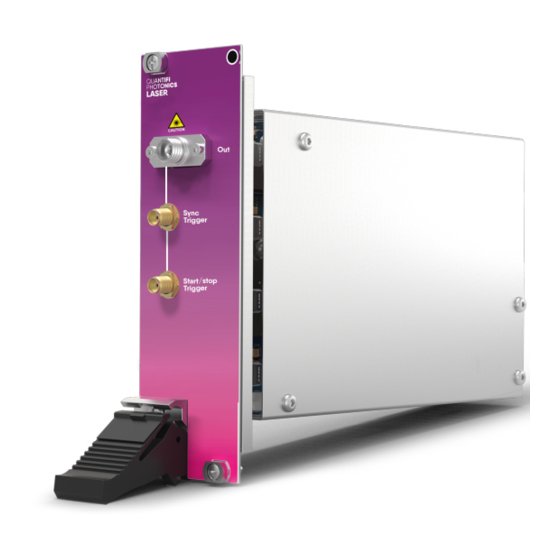
Sync trigger output (SMA max 3.3V TTL) Fastening screw Start/stop trigger output (SMA max 3.3V TTL) PXIe header Product label Module identifier label Product compliance label 13 / 95 Quantifi Photonics | LASER 2000 PXIe Series User Manual | Version 1.02... -
Page 14: Status Leds
Do NOT look into the fiber or inspect it while the laser is ENABLED / ON! During startup: Indicates the initialization of the LASER module. flashing RED After startup, if flashing persists for more than 15 seconds: Indicates an error. 14 / 95 Quantifi Photonics | LASER 2000 PXIe Series User Manual | Version 1.02... -
Page 15: Operation Modes
If the device is configured for multiple sweeps, the laser returns to the start wavelength after getting to the end of the step range and repeats the sweep as above. Start/stop trigger signal in step mode: 15 / 95 Quantifi Photonics | LASER 2000 PXIe Series User Manual | Version 1.02... - Page 16 The following table lists various sync trigger parameters against typical sweep speeds. Δ WL is the change in wavelength for every sync pulse. Sweep speed (nm/s) Period (μs) Pulse width (μs) Δ WL (pm) 66.7 62.5 66.7 16 / 95 Quantifi Photonics | LASER 2000 PXIe Series User Manual | Version 1.02...
- Page 17 Sweep speed (nm/s) Period (μs) Pulse width (μs) Δ WL (pm) 17 / 95 Quantifi Photonics | LASER 2000 PXIe Series User Manual | Version 1.02...
-
Page 18: Trigger Output Signal
inverting the polarity of the signal (refer Polarity inversion) setting a decimation factor to reduce the number of trigger pulses (refer Decimation factor 18 / 95 Quantifi Photonics | LASER 2000 PXIe Series User Manual | Version 1.02... - Page 19 By default the unmodified signal is active high, meaning the logic level is high when there is activity. When inverting the signal, the signal will be flipped and becomes active low. Polarity Signal 0 (default) active high active low 19 / 95 Quantifi Photonics | LASER 2000 PXIe Series User Manual | Version 1.02...
- Page 20 <N> 0 (default) the generated signal remains unchanged skip 1 pulse after the first pulse, repeat skip 3 pulses after the first pulse, repeat Examples 20 / 95 Quantifi Photonics | LASER 2000 PXIe Series User Manual | Version 1.02...
-
Page 21: Setting Up Hardware
Ensure that the chassis being used supports PXIe (or contains PXI-hybrid compatible slots). If you are unsure if your chassis is compatible with your Quantifi Photonics product, please contact Quantifi Photonics Customer Support. Make sure to follow these instructions when installing or removing a Quantifi Photonics module from a PXIe chassis. CAUTION The product is sensitive to electrostatic discharge (ESD). - Page 22 Push module into slot until you feel Engage the fastening clip. Secure all Power the chassis ON. resistance from the backplane connection. fastening screws. 22 / 95 Quantifi Photonics | LASER 2000 PXIe Series User Manual | Version 1.02...
- Page 23 Use the fastening clip to pull. Do NOT pull on the connectors. Store the module in its antistatic bag. Power ON the chassis. 23 / 95 Quantifi Photonics | LASER 2000 PXIe Series User Manual | Version 1.02...
-
Page 24: Installing Software
6 Installing software The Cohesion Installer software package enables communication between the PXIe controller and Quantifi Photonics modules installed in a chassis. The Cohesion Installer contains all required drivers and software: CohesionDriver Driver Service for Quantifi Photonics PXIe modules CohesionSCPI... - Page 25 1. We recommended that you save your work and close open programs before installing Cohesion Installer. 2. Locate and run CohesionInstaller-<version_number>.exe from the provided USB media device (or download it from the Quantifi Photonics website) and follow the on-screen installation prompts.
- Page 26 7. On startup after rebooting the system a User Account Control prompt might be displayed. Click Yes to allow running of the Cohesion Firmware Updater Utility and proceed with the application. 26 / 95 Quantifi Photonics | LASER 2000 PXIe Series User Manual | Version 1.02...
- Page 27 VXI11 compliant SCPI interface for TCP communication with the installed Quantifi Photonics modules CohesionUI optional web service providing a graphical interface for simplified operation of installed Quantifi Photonics modules To open Cohesion Manager: Search for Cohesion Manager in the Windows Start Menu.
- Page 28 Cohesion Manager application. It is a single-window summary application that enables you to: view the current firmware status of all Quantifi Photonics PXIe modules installed in the chassis. update firmware to a new version if available.
- Page 29 7 CohesionUI - Overview CohesionUI is a web-based graphical interface that you can use to work with your Quantifi Photonics products. CohesionUI is part of the Cohesion Installer software package. For details on Cohesion Installer, refer Installing software. 1. HOME: View all modules in the chassis 2.
- Page 30 7.1 Access a module with CohesionUI You can access Quantifi Photonics modules via CohesionUI from the chassis controller, or from a controller PC . To connect with a module, you need the IP address of the chassis the module is installed in.
- Page 31 7.2 Display modules in a chassis The HOME page is the main landing page in CohesionUI; it displays all available Quantifi Photonics modules in the PXIe chassis. 1. Numbers indicate the slots the modules are installed in. 2. You can hide (default setting) or show empty slots in the PXIe chassis by toggling the EMPTY SLOTS button.
- Page 32 1. Go to the HOME page. 2. Click the on the module. 3. Or, hover over the MODULES menu and select a module or channel from the list. 32 / 95 Quantifi Photonics | LASER 2000 PXIe Series User Manual | Version 1.02...
-
Page 33: Set Values
To set a pre-defined value, for example MIN, MAX or DEF: 4. Click on a parameter and select a value from the dropdown menu. 5. Confirm the value. 33 / 95 Quantifi Photonics | LASER 2000 PXIe Series User Manual | Version 1.02... - Page 34 : The actual value of the parameter as queried by the product. SET: The intended value of a given parameter as set by the user. For details on how to set values, refer values. 34 / 95 Quantifi Photonics | LASER 2000 PXIe Series User Manual | Version 1.02...
- Page 35 2. Change settings or unit preferences as required, for example temperature units. 3. Step size refers to the amount by which a value is increased or decreased when clicking the + or - button. 35 / 95 Quantifi Photonics | LASER 2000 PXIe Series User Manual | Version 1.02...
- Page 36 To adjust unit preferences one at a time: 1. Hover over SETTINGS. 2. Select a unit from the dropdown, for example the power unit. 36 / 95 Quantifi Photonics | LASER 2000 PXIe Series User Manual | Version 1.02...
- Page 37 7.7 Synchronize and reinitialize CohesionUI You can update CohesionUI with the latest information from your Quantifi Photonics modules by synchronizing or reinitializing. Synchronizing Updates CohesionUI with the latest information from the CohesionSCPI service Reinitializing Updates CohesionUI and the CohesionSCPI service with the latest information from the CohesionDriver service This can be particularly useful when operating a multi-chassis MXI setup and enables you to: ...
- Page 38 To reinitialize CohesionUI across all modules in all chassis: 1. Click SETTINGS. 2. Click RE-INIT. 3. All modules will be disabled and temporarily disconnected while reinitializing. 38 / 95 Quantifi Photonics | LASER 2000 PXIe Series User Manual | Version 1.02...
- Page 39 7.8 SCPI CohesionUI Command Console The CohesionUI SCPI Command Console enables you to communicate with Quantifi Photonics PXIe modules via SCPI commands. It enables you to test commands and verify their syntax. For details on available SCPI commands, refer to the programming guide in this manual.
- Page 40 For details on error codes, please refer to the programming guide in this manual. Clear the response buffer and start fresh – useful when getting out of sync with WRITE *CLS and READ actions 40 / 95 Quantifi Photonics | LASER 2000 PXIe Series User Manual | Version 1.02...
- Page 41 8. The instrument returns the error code, for example 32. For details on error codes, please refer to the *ESR? command in the programming guide. 41 / 95 Quantifi Photonics | LASER 2000 PXIe Series User Manual | Version 1.02...
-
Page 42: View System Information
To view module information when working with a module in CohesionUI: 1. Model number, serial number and firmware versions are displayed in the top right corner. 42 / 95 Quantifi Photonics | LASER 2000 PXIe Series User Manual | Version 1.02... - Page 43 8 Controlling your LASER with CohesionUI You can use Quantifi Photonics' graphical user interface CohesionUI to work with your LASER module. For details on how to get started with CohesionUI, refer to CohesionUI - Overview. We recommend that you run a power reference scan when you start or restart the LASER module. This measures and stores the output optical power across the wavelength range and enables you to reference these measurements against connected measurement tools.
-
Page 44: Step Mode
To start/stop the sweep: 4. Set Laser state to ON. 5. Click Start to start the sweep. You can stop a sweep at any time by clicking Stop. 44 / 95 Quantifi Photonics | LASER 2000 PXIe Series User Manual | Version 1.02... -
Page 45: Sweep Mode
To start/stop the sweep: 4. Set Laser state to ON. 5. Click Start to start the sweep. You can stop a sweep at any time by clicking Stop. 45 / 95 Quantifi Photonics | LASER 2000 PXIe Series User Manual | Version 1.02... -
Page 46: Fixed Mode
1. Select Operation mode: FIXED. 2. Set the wavelength. The current laser output power reading for this wavelength will be displayed. 3. Set Laser state to ON. 46 / 95 Quantifi Photonics | LASER 2000 PXIe Series User Manual | Version 1.02... - Page 47 To run a power reference scan: 1. Select Operation mode: FIXED. 2. Set Laser state to ON. 3. Click Run Power Reference Scan. 47 / 95 Quantifi Photonics | LASER 2000 PXIe Series User Manual | Version 1.02...
-
Page 48: Trigger Controls
3. Select the trigger line(s) and click Set masks to route the signal(s) to the selected trigger lines. Each trigger line can only carry either the sync or the start/stop trigger signal. 48 / 95 Quantifi Photonics | LASER 2000 PXIe Series User Manual | Version 1.02... - Page 49 For details on available SCPI commands, refer: Command summary Command descriptions For details on the module's operation modes and trigger output signals, refer Introducing the LASER 2000 Series. 49 / 95 Quantifi Photonics | LASER 2000 PXIe Series User Manual | Version 1.02...
-
Page 50: Programming Conventions
The output queue stores responses to query commands. The CohesionSCPI service transmits any data in the output queue when a read request is received. Unless specified, all output response data is transmitted in ASCII format. 50 / 95 Quantifi Photonics | LASER 2000 PXIe Series User Manual | Version 1.02... - Page 51 9.3 Status and event registers 9.3.1 Standard Event Status Register The Standard Event Status Register (SESR) is modified by the Quantifi Photonics product with the results of the command operations. Description 7 (MSB), 6 Not used Is set when a Command Error event has been detected...
- Page 52 The Event Status Bit (ESB) is set from the SESR and the SESR Mask Message Available (MAV) is set when there is data in the output queue 3, 2, 1, 0 (LSB) Not used 52 / 95 Quantifi Photonics | LASER 2000 PXIe Series User Manual | Version 1.02...
- Page 53 9.3.5 Status and event registers diagram 53 / 95 Quantifi Photonics | LASER 2000 PXIe Series User Manual | Version 1.02...
- Page 54 In the example shown below, there are two chassis connected via the PXIe-8384 to PXIe-8381 connection. Chassis #2 has the controller running CohesionSCPI service, and Chassis #3 is the ‘extended’ chassis. 54 / 95 Quantifi Photonics | LASER 2000 PXIe Series User Manual | Version 1.02...
- Page 55 Set CohesionSCPI service to operate in SINGLE Chassis Mode Parameters MULTI Set CohesionSCPI service to operate in MULTI Chassis Mode Response No response Example :SYSTEM:CHASSIS SINGLE 55 / 95 Quantifi Photonics | LASER 2000 PXIe Series User Manual | Version 1.02...
- Page 56 In Multi chassis mode, all the commands given above in the Specific Command Summary will still work, but they must be prefixed with :CHASSIS<c>. Common command example: Single Chassis Mode :SLOT2:IDN? Multi Chassis Mode :CHASSIS1:SLOT2:IDN? Specific command example: Single Chassis Mode :SOUR2:CHAN2:POW? MAX Multi Chassis Mode :CHASSIS1:SOUR2:CHAN2:POW? MAX 56 / 95 Quantifi Photonics | LASER 2000 PXIe Series User Manual | Version 1.02...
-
Page 57: Command Summary
Query the Operation Complete Status of the module >> :IDN? Query the slot identification >> :OPTions? Query the modules managed by the CohesionSCPI service >> :TEMPerature? Query the Temperature of the module 57 / 95 Quantifi Photonics | LASER 2000 PXIe Series User Manual | Version 1.02... - Page 58 >> :POWer? Query the output optical power fixed mode >> :SCAN Run a power reference scan >> :WAVelength/? Set / Query the current laser wavelength 58 / 95 Quantifi Photonics | LASER 2000 PXIe Series User Manual | Version 1.02...
- Page 59 Set/Query polarity of the signal (module Sync trigger output) Sync trigger :BACKplane >> :POLArity/? Set/Query polarity of the signal (PXI backplane trigger lines) >> :LINEs/? Set/Query the PXI backplane trigger lines 59 / 95 Quantifi Photonics | LASER 2000 PXIe Series User Manual | Version 1.02...
-
Page 60: Command Descriptions
NOTE: Any commands sent to the module when :MODUle<slot>:OPC? is NOT equal 1, may not execute or return an error. Example *OPC? -> 1 60 / 95 Quantifi Photonics | LASER 2000 PXIe Series User Manual | Version 1.02... - Page 61 Query the Standard Event Status Enable Register (Mask) Parameters Response Unsigned integer 8 bit value for the register <0 to 255>, as a string. Example *ESE? -> 254 61 / 95 Quantifi Photonics | LASER 2000 PXIe Series User Manual | Version 1.02...
- Page 62 Query the module self-test status Parameters Response Functional readiness status of the module. A non-zero response reports an error. :SLOT1:TST? Example -> 0 62 / 95 Quantifi Photonics | LASER 2000 PXIe Series User Manual | Version 1.02...
- Page 63 Query the modules managed by the CohesionSCPI service Parameters Response A comma separated array, or a single integer value based on the arguments given :SLOT3:OPTions? Example -> 1,,,,,,, 63 / 95 Quantifi Photonics | LASER 2000 PXIe Series User Manual | Version 1.02...
- Page 64 Enables laser output of <value> in the default Power unit Parameters OFF: Disables laser output ON: Enables laser output Response Example :OUTPut9:STAT ON 64 / 95 Quantifi Photonics | LASER 2000 PXIe Series User Manual | Version 1.02...
- Page 65 STEP: Sets the operation mode to step mode SWEEP: Sets the operation mode to sweep mode Response Example :OUTP9:MODE STEP 65 / 95 Quantifi Photonics | LASER 2000 PXIe Series User Manual | Version 1.02...
- Page 66 STEP = 1 allows values of 1, 2, 3 etc. STEP = 0.1 allows values of 1.1, 1.2, 1.3 etc. Response Example :OUTP9:SWEE:NUMB? ALL -> 0,65535,1,1 66 / 95 Quantifi Photonics | LASER 2000 PXIe Series User Manual | Version 1.02...
- Page 67 MIN: Sets the minimum starting wavelength Parameters MAX: Sets the maximum starting wavelength DEF: Sets the default starting wavelength Response Example :OUTP9:SWEE:WAV:STAR 1245000 67 / 95 Quantifi Photonics | LASER 2000 PXIe Series User Manual | Version 1.02...
- Page 68 MIN: Sets the minimum stopping wavelength Parameters MAX: Sets the maximum stopping wavelength DEF: Sets the default stopping wavelength Response Example :OUTP9:SWEE:WAV:STOP 1305000 68 / 95 Quantifi Photonics | LASER 2000 PXIe Series User Manual | Version 1.02...
- Page 69 >> :OUTPut<slot>:STEP:STARt Start wavelength sweep. Description NOTE: The laser state must be ON to start this operation. Parameters Response Example :OUTP9:STEP:STAR 69 / 95 Quantifi Photonics | LASER 2000 PXIe Series User Manual | Version 1.02...
- Page 70 STEP = 1 allows values of 1, 2, 3 etc. STEP = 0.1 allows values of 1.1, 1.2, 1.3 etc. Response Example :OUTP9:STEP:NUMB? ALL -> 0,65535,1,1 70 / 95 Quantifi Photonics | LASER 2000 PXIe Series User Manual | Version 1.02...
- Page 71 MIN: Sets the minimum starting wavelength Parameters MAX: Sets the maximum starting wavelength DEF: Sets the default starting wavelength Response Example :OUTP9:STEP:WAV:STAR DEF 71 / 95 Quantifi Photonics | LASER 2000 PXIe Series User Manual | Version 1.02...
- Page 72 MIN: Sets the minimum stopping wavelength Parameters MAX: Sets the maximum stopping wavelength DEF: Sets the default stopping wavelength Response Example :OUTP9:STEP:WAV:STOP DEF 72 / 95 Quantifi Photonics | LASER 2000 PXIe Series User Manual | Version 1.02...
- Page 73 MIN: Sets the minimum step size Parameters MAX: Sets the maximum step size DEF: Sets the default step size Response Example :OUTP9:STEP:WAV:STEP MAX 73 / 95 Quantifi Photonics | LASER 2000 PXIe Series User Manual | Version 1.02...
- Page 74 ACT: Returns the actual measured power reading Parameters UNIT: Returns the default power unit Response Example :SOUR9:POW? ACT -> 15.108000 74 / 95 Quantifi Photonics | LASER 2000 PXIe Series User Manual | Version 1.02...
- Page 75 MIN: Sets the minimum wavelength Parameters MAX: Sets the maximum wavelength DEF: Sets the default wavelength Response Example :SOUR9:WAV DEF 75 / 95 Quantifi Photonics | LASER 2000 PXIe Series User Manual | Version 1.02...
- Page 76 INFO: Returns the mapping between the numeral and the text form of the control mode Response :TRIG9:POLA? INFO -> Example 0:OFF,POSITIVE 1:ON,NEGATIVE 76 / 95 Quantifi Photonics | LASER 2000 PXIe Series User Manual | Version 1.02...
- Page 77 SET: Returns the PXI trigger line selection mask that is set for the start/stop trigger output signal Response Example :TRIG9:BACK:LINE? SET -> 0 77 / 95 Quantifi Photonics | LASER 2000 PXIe Series User Manual | Version 1.02...
- Page 78 MIN: Sets the minimum decimation factor Parameters MAX: Sets the maximum decimation factor DEF: Sets the default decimation factor Response Example :TRIG9:SYNC:DECI MAX 78 / 95 Quantifi Photonics | LASER 2000 PXIe Series User Manual | Version 1.02...
- Page 79 Set polarity of the signal 1|ON|NEGATIVE: Inverts polarity to active low Parameters 0|OFF|POSITIVE: (default) Sets polarity to active high Response Example :TRIG9:SYNC:BACK:POLA POSITIVE 79 / 95 Quantifi Photonics | LASER 2000 PXIe Series User Manual | Version 1.02...
- Page 80 Set the PXI trigger line mask for the sync trigger output signal Parameters <mask>: Routes the trigger output signal to these PXI trigger lines Response Example :TRIG9:SYNC:BACK:LINE 7 80 / 95 Quantifi Photonics | LASER 2000 PXIe Series User Manual | Version 1.02...
-
Page 81: Programming Applications
In NI-MAX a RIO interface will show up, however there are no communication methods available or implemented on this interface. Quantifi Photonics products are ONLY accessible through the VISA TCPIP INSTR interface provided by the CohesionSCPI service installed on the system. - Page 82 3. Select Manual Entry of LAN Instrument. Enter in the Hostname or IP Address. Note when operating locally, enter in the localhost IP address of 127.0.0.1. Click Finish to end the setup process. 82 / 95 Quantifi Photonics | LASER 2000 PXIe Series User Manual | Version 1.02...
- Page 83 2. On the right-hand side panel, select Open VISA Test Panel. A new window will popup. Click the Input / Output button from the window menu. Valid chassis and module commands can be entered in, and their returns queried 83 / 95 Quantifi Photonics | LASER 2000 PXIe Series User Manual | Version 1.02...
- Page 84 10.3 Setting up LabVIEW application 10.3.1 Soft Panels To control a Quantifi Photonics product with a LabVIEW Soft Panel, you will have to set up the product as a TCP/IP instrument (refer Setting up NI-MAX application). 1. Download the LabVIEW zip file from the Quantifi Photonics website. This contains all Soft Panels and Virtual Instruments (VIs) for Quantifi Photonics products.
- Page 85 10.3.2 LabVIEW Virtual Instruments (VIs) Instead of using the Soft Panels, you can also use the Virtual Instruments to control a Quantifi Photonics product from within LabVIEW. These VIs are provided for customers who want to develop custom applications using the Quantifi Photonics products.
- Page 86 10.4 Python® 2.7 code example The following example shows how to communicate with the Quantifi Photonics product using Python code. For a list of supported and valid SCPI commands, refer to the Programming Guide. # You can get VXI11 from pip: # pip install python-vxi11==0.9...
- Page 87 % Replace this with a valid command for your device (read the programming % guide section for examples) command = % Close the connection to the object. 87 / 95 Quantifi Photonics | LASER 2000 PXIe Series User Manual | Version 1.02...
- Page 88 Always inspect fiber end faces for cleanliness using a fiber inspection probe before inserting them into a port.. If required, clean fibers and faces as detailed below. Quantifi Photonics is not responsible for damage or errors caused by bad fiber cleaning or handling. NOTE To avoid damaging ferrules or fiber faces due to mismatched connectors, always check ports and connector type information before inserting a connector.
- Page 89 If your connector features a screw sleeve, tighten the connector to firmly maintain the fiber in place. Do not over-tighten, as this will dam- age the fiber and the port bulkhead. NOTE Failing to align and/or connect fiber-optic cables properly will result in significant signal loss and reflection. 89 / 95 Quantifi Photonics | LASER 2000 PXIe Series User Manual | Version 1.02...
-
Page 90: System Requirements
Quantifi Photonics MATRIQ / EPIQ instruments Google Chrome™ Supported browsers for working with CohesionUI Microsoft Edge® Recommended client computer operating system Microsoft Windows® 10 (64-bit) 90 / 95 Quantifi Photonics | LASER 2000 PXIe Series User Manual | Version 1.02... -
Page 91: Maintenance
All Quantifi Photonics products are calibrated during manufacture, and each product is shipped to the customer with a Calibration Certificate. On this certificate, the calibration date, as well as the next calibration due date are mentioned. -
Page 92: Contacting The Technical Support Group
14 Technical Support 14.1 Contacting the Technical Support Group To obtain after-sales service or technical support for this product, contact Quantifi Photonics: support@quantifiphotonics.com To accelerate the process, please provide information such as the name and the serial number (see the product identification label), as well as a description of your problem. - Page 93 15.2 Liability Quantifi Photonics shall not be liable for damages resulting from the use of the product, nor shall be responsible for any failure in the performance of other items to which theproduct is connected or the operation of any system of which the product may be a part.
-
Page 94: Service And Repairs
Quantifi Photonics. 15.4 Certification Quantifi Photonics certifies that this equipment met its published specifications at the time of shipment from the factory. 15.5 Service and repairs To send any equipment for service, repair or calibration please contact the Technical Support Group. - Page 95 Measure. Solve. Quantifi Photonics is transforming the world of photonics test and measurement. Our portfolio of optical and electrical test instruments is rapidly expanding to meet the needs of engineers and scientists around the globe. From enabling ground- breaking experiments to driving highly efficient production testing, you'll find us working with customers to solve complex problems with optimal solutions.