
Related Manuals for Heat Link SSP Series

Summary of Contents for Heat Link SSP Series
- Page 1 ® Heat Link SSP Series Installation, Operation, and Maintenance Manual °C °F...
-
Page 3: Table Of Contents
Installation, Operation, and Maintenance Manual Table of Contents SSP Series Product Safety Information ............... Warnings ....................Servicing ....................Function ......................Unpacking ...................... Installation Tools Needed ................Panel Configurations ................... Panel Dimensions ..................Panel Components (Diagram) ..............Panel Components Breakdown .............. -
Page 4: Product Safety Information
Installation, Operation, and Maintenance Manual SSP Series Product Safety Information Warnings The zone control panel is for indoor use only and must be installed by a qualifi ed installer/service technician. This product must be installed and operated in strict accordance with the terms set out in this manual and in accordance with the relevant requirements of the Local Authority Having Jurisdiction. -
Page 5: Unpacking
Installation, Operation, and Maintenance Manual SSP Series Unpacking Examine carton for any damage that may have occurred during shipping. If damage is visible Step 1 notify your courier and supplier immediately. Open the carton by cutting the straps and removing the lid. -
Page 6: Panel Configurations
Installation, Operation, and Maintenance Manual SSP Series Panel Configurations SSP panels are available in the mechanical configurations illustrated below. SSP panels are available with 4, 6, 8, 10, or 12 loop manifolds in a surface mount recessed cabinet. °C °C °F... -
Page 7: Panel Dimensions
Installation, Operation, and Maintenance Manual SSP Series Panel Dimensions Bottom View Enclosure Dimensions Cover Dimensions (Recessed) Cover Dimensions (Surface) # of # of Loops Locks ⁄ " ⁄ " ⁄ " 36" 30" ⁄ " 26.9" (876 mm) (724 mm) -
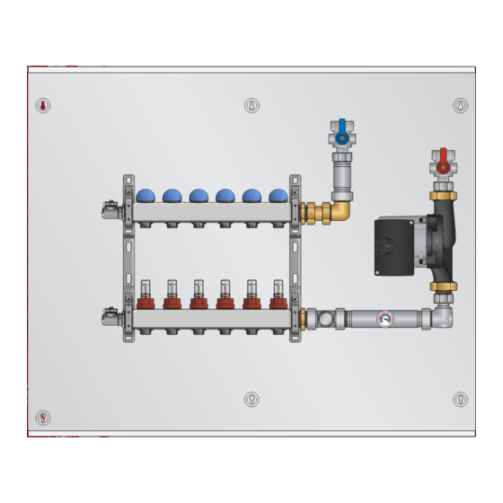
Page 8: Panel Components (Diagram)
Installation, Operation, and Maintenance Manual SSP Series Panel Components (Diagram) °C °F °C °F Small pump assembly, top feed (SSPSx100T panels) SSPLx106T shown Small pump assembly, bottom feed (SSPSx100T panels) °C °F °C °F L6SSP Series Mechanical Manual ® Heat... -
Page 9: Panel Components Breakdown
Installation, Operation, and Maintenance Manual SSP Series Panel Components Breakdown Part Number (Qty.) Components Component Description/Specifications SSPSx1xxx SSPLx1xxx SSPLx2xxx The pump moves heated fluid through the UPS15-58 UPS26-99 UPS26-99 Pump hydronic system when there is a call for heat from the thermostat. Factory set to 3rd speed. -
Page 10: Pump Curves
Installation, Operation, and Maintenance Manual SSP Series Pump Curves UPS15-58CIL2 Pump Curve Type UPS 15-58 CIL2 P/N: 97948357 115 V ~ PC: 1131HLK 60 Hz 8 μF (A) P |1/1 IP42 0.51 TF 95 0.59 Max. 1.0MPa 0.64 203°F Max. water temp. -
Page 11: Optional Add-Ons
Installation, Operation, and Maintenance Manual SSP Series Optional Add-Ons SSATH - Optional Installed Accessory Thermostatic Head Used as thermostatic control for the mixing valve. Specifications: • Temperature Setting Range: 68-158°F (20-70°C) • Sensor: Liquid filled contact sensor Notes: Do not use any tools when installing the thermostatic head... -
Page 12: Panel Mounting - Recessed Enclosure
Installation, Operation, and Maintenance Manual SSP Series Panel Mounting - Recessed Enclosure Prior to mounting the panel, ensure the wall is capable of supporting the weight of the panel, and that all ⁄ " ⁄ " required power outlets and/or wiring is available at the installation location. -
Page 13: Panel Mounting - Surface Enclosure
Installation, Operation, and Maintenance Manual SSP Series Panel Mounting - Surface Enclosure Prior to mounting the panel, ensure the wall is capable of supporting the weight of the panel, and that the required 110V wiring is available at the installation location. See controls manual for wiring details. -
Page 14: Piping Hookup
Installation, Operation, and Maintenance Manual SSP Series Piping Hookup Before making any connections, identify the required connections to and from the panel. Step 1 Connect mains piping using 1" MNPT fittings. Step 2 Connect all tubing to manifold connectors (77100 connectors sold separately). -
Page 15: Pex Tubing To Manifold Connections
Installation, Operation, and Maintenance Manual SSP Series PEX Tubing to Manifold Connections using #77100 Series Connectors (sold separately) 77105 ½", and 77119 ⅝" Connectors include a nut and split ring ferrule pre-assembly, and a brass insert with O-ring. Brass Insert Nut &... -
Page 16: Fill & Purge
Installation, Operation, and Maintenance Manual SSP Series Fill & Purge The following steps are recommended in order to fill the panel with water and purge entrained air once piping is completed, and before activation of the panel. Use a pail to collect and dispose of the purged fluid. - Page 17 Installation, Operation, and Maintenance Manual SSP Series From main supply line Purge °C °F hose (not included) Notes • Hose bib thread is ¾" GH thread.❷ • After fill procedure: the drip cap ❶ should be placed back on to the hose bib ❷...
-
Page 18: Balancing (75100 Series With Flow Meters)
Installation, Operation, and Maintenance Manual SSP Series Balancing (75100 series with Flow Meters) HeatLink Stainless Steel Manifolds (75000 series) are balanced on the supply side only. Remove locking cap to adjust flow meter. Flow Meter Opening Turns Please note: Do not use tools to adjust 0.35... -
Page 19: 75100 Series Friction Head Graph
Installation, Operation, and Maintenance Manual SSP Series 75100 Series Friction Head Graph 1.25 1.75 Turns from closed position 30 (90) 2.25 2.75 10 (30) 5 (15) 1 (3) 0.5 (1.5) 0.1 (0.3) (0.38) (1.89) (3.78) (7.57) (11.36) Flow rate US gpm (L/min.) 75100 Series Technical Data Operating pressure .....................87 psi (6 bar) -
Page 20: 75200 Series Friction Head Graph
Installation, Operation, and Maintenance Manual SSP Series 75200 Series Friction Head Graph Turns from closed position 30 (90) 10 (30) F.O. 5 (15) 1 (3) 0.5 (1.5) 0.1 (0.3) (0.38) (1.89) (3.78) (11.36) (18.93) Flow rate US gpm (L/min.) 75200 Series Technical Data Operating pressure ....................145 psi (10 bar) -
Page 21: Troubleshooting
Installation, Operation, and Maintenance Manual SSP Series Troubleshooting Problem Check / Verify Possible Cause Low Temperature Within Room Misplacement of thermostat location Make sure thermostat is not being within room. influenced by an additional heat source, such as lighting or air duct. -
Page 22: Differential Piping Schematic
Installation, Operation, and Maintenance Manual SSP Series Differential piping schematic The recommended pressure differential for SSP panels is 20psi. In systems where there is a pressure differential higher than 20psi, SSPS panels (with the UPS15-58 pump) should be piped as per the schematic below to avoid valve noise or damage. - Page 23 ® Installation, Operation, and Maintenance Manual Heat Link SSP Series www.heatlink.com...
- Page 24 www.heatlink.com January 24, 2024 Printed in Canada ©HeatLink Group Inc.
Need help?
Do you have a question about the SSP Series and is the answer not in the manual?
Questions and answers