Advertisement
Quick Links
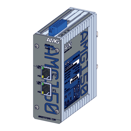
INTERFACE CONNECTIONS
① Insert the incoming Cat5/6
data cable into either RJ45 port.
② Insert the outgoing Cat5/6 PoE
cable into either RJ45 port.
Note: PoE can be delivered from
ports P1 & P2 at the same time
allowing for up to 2 PoE devices to
be powered.
PORT SPEEDS
Example part code:
AMG150-2GAT-P60
Character
F
G
POE CAPABILITIES
Example part code:
AMG150-2GAT-P60
Characters
PoE Standard Supported
None
Non-PoE Model
AT
IEEE 802.3at 30W Port
BT
IEEE 802.3bt 60/90W Port
Check the product label to determine
the PoE power supported on each port
and the units total maximum PoE budget.
AMG Systems Ltd. 4 Pioneer Way, Castleford, WF10 5QU, UK T: +44 (0) 1767 600 777 E: technical@amgsystems.com
AMG Systems Inc. 62 Spring Hill Road, Trumbull, CT 06611, USA T: +1-855-AMGPOE1 (855-264-7631)
D33205-02
RJ45 Port Speed
10/100 Base-T(X)
10/100/1000 Base-T(X)
Ensure the PSU size
used is at least equal
to the maximum PoE
budget figure.
Characters
PoE Budget
IEEE 802.3at Models
P30
30W Max
Type 1 & 2 PoE support
P60
60W Max
Mode A PSE only
P90
90W Max
IEEE 802.3bt Models
P180
180W Max
Type 1, 2, 3 & 4 PoE
support. Mode A
and/or Mode B PSE
www.amgsystems.com
Industrial 2-Port PoE Injector
Industrial 2-Port PoE Injector
amgsystems.com
AMG150 Series
AMG150 Series
Installation Manual - Hardware
Installation Manual - Hardware
Advertisement

Related Manuals for AMG AMG150

Summary of Contents for AMG AMG150
- Page 1 Mode B PSE and the units total maximum PoE budget. AMG Systems Ltd. 4 Pioneer Way, Castleford, WF10 5QU, UK T: +44 (0) 1767 600 777 E: technical@amgsystems.com amgsystems.com AMG Systems Inc. 62 Spring Hill Road, Trumbull, CT 06611, USA T: +1-855-AMGPOE1 (855-264-7631) D33205-02 www.amgsystems.com...
- Page 2 DIN RAIL MOUNT INSTALLATION SURFACE MOUNT INSTALLATION IP RATING ① Remove the DIN rail clip by unscrewing the two fixing screws as shown. ② Attach the included wall mount brackets with the To maintain the units IP40 rating any provided 4 x M3 screws as screw holes that are not used should still shown.
Need help?
Do you have a question about the AMG150 and is the answer not in the manual?
Questions and answers