
Related Manuals for LG LFC23760ST/03


Summary of Contents for LG LFC23760ST/03
- Page 1 REFRIGERATOR SERVICE MANUAL CAUTION BEFORE SERVICING THE UNIT, READ THE SAFETY PRECAUTIONS IN THIS MANUAL. MODELS: LFC23760ST / 03 LFC23760SW / 03 LFC23760SB / 03...
- Page 2 ECN (Engineering Change Number) Rev.01 Change Cover Lower, Case PCB and Rail Rev.02 Change compressor & base compressor Holder,Shelf Cover,Lamp Door Assembly,Refrigerator(Left) Door Foam Assembly,Refrigerator Cover Assembly,Display Cap Assembly,Duct Cover Assembly,Machinery(Rear) Compressor,Set Assembly Thermistor Assembly,PTC Overload Protect Cover,Relay Grille Assembly,Fan Motor,DC Bracket Assembly,Motor PCB Assembly...
-
Page 3: Table Of Contents
CONTENTS SAFETY PRECAUTIONS ......................1. SPECIFICATIONS ....................... 2. PARTS IDENTIFICATION ....................3. DISASSEMBLY ........................3-1 Fan and Fan Motor......................3-2 Defrost Control Assembly....................3-3 Lamp..........................3-4 Control Box Refrigerator....................3-5 Multiduct.......................... 3-6 Cover Valve........................3-7 Door Disassembly......................3-8 How to remove the Door Handle..................3-9 How to remove Pull out drawer.................. -
Page 4: Safety Precautions
SAFETY PRECAUTIONS Please read the following instructions before servicing your refrigerator. 1.Check the refrigerator for current leakage. 7.Before tilting the refrigerator, remove all materials from on or in the refrigerator. 2.To prevent electric shock,unplug before servicing. 8.When servicing the evaporator, wear gloves to prevent injuries from the sharp evaporator 3.Always check line voltage and amperage. -
Page 5: Specifications
1. SPECIFICATIONS LFC23760SW LFC23760ST LFC23760SB SPECIFICATIONS Color Super White Stainless Black 892 (W) x 925 (D) x 1860 (H) mm Dimensions Net Weight 123 Kg Capacity 23 cuft Refrigerant R134a Climate class Temperate (T) Rated Rating 115V~ / 60Hz Cooling System Fan Cooling Temperature Control MICOM control... - Page 6 DIMENSIONS Description LFC23760** Depth w/ Handles Depth w/o Handles Depth w/o Door 28 ¼ Depth (Total with Door Open) 45 ½ Height to Top of Case Height to Top of Door Hinge Width 32 ¾ Width (door open 90 deg. w/o handle) 36 ¼...
-
Page 7: Parts Identification
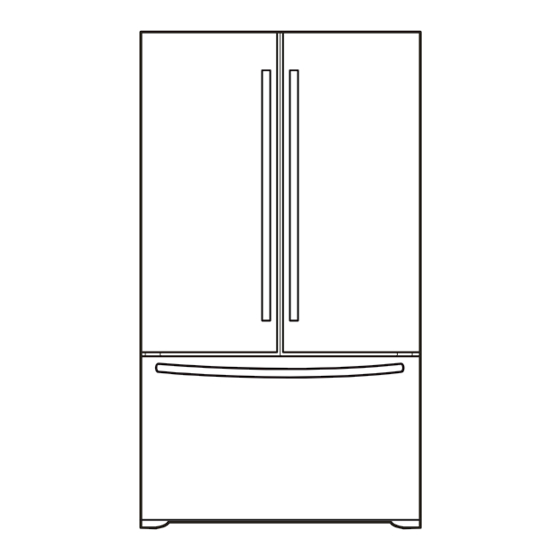
2. PARTS IDENTIFICATION Read this section to familiarize yourself with the parts and features of your new refrigerator. NOTE: This guid ecovers different models. Your refrigerator could have some or all of the features and parts listed below. The location of some of the parts may not correspond to that of your model. Ice Bin Digital Sensor Control Durabase... - Page 8 Read this section to familiarize yourself with the parts and features of your new refrigerator. NOTE: This guid ecovers different models. Your refrigerator could have some or all of the features and parts listed below. The location of some of the parts may not correspond to that of your model. Digital Sensor Control * Durabase Refrigerator Light...
-
Page 9: Disassembly
3. DISASSEMBLY 3-1 FAN AND FAN MOTOR 3-3 LAMP 3-3-1 REFRIGERATOR COMPARTMENT LAMP 1. Remove the freezer shelf. (If your refrigerator has an 1. Unplug your refrigerator. icemaker, remove the icemaker first). 2. Pull out all of the shelves. 2. Remove the plastic guide for slides on left side by 3. -
Page 10: Control Box Refrigerator
3-4 CONTROL BOX-REFRIGERATOR 1. First, remove all shelves in the refrigerator, than remove the Refrigerator control Box by loosening 2 screws. CONTROL BOX COVER LAMP 2. Remove the Refrigerator Control Box by pulling it downward. 3. Disconnect the lead wire on the right position and separate the lamp sockets. 3-5 MULTI DUCT 1. - Page 11 3-6 VALVE COVER (in some models) 3-6-1 DISASSEMBLE 3-6-2 ASSEMBLE 1. Unscrew the back cover. 1. Insert the ribs to the right side of the back cover hole. 2. Screw the valve cover from the back side. 2. Unscrew the valve cover from the back side.
-
Page 12: Door Disassembly
3-7 DOOR DISASSEMBLY 1. To remove Refrigerator door IMPORTANT: Before you begin, turn the refrigerator OFF and Right Door Unplug it. Remove all food and the shelves from the doors. Left Door NOTE: The appearance of the handle might be different. With the Philips screw driver, loose the two screws from the upper lid (1) remove it after that. - Page 13 Front view of the harness Right Door Loose the grounding screw (9) and the pins (10) located over the hinge, after, lift the hinge and remove it (11). Place the hinge in its original position (4) assembly the two pins (5) and the ground screws (6). Remove the door and place it over its inner face to avoid scratching.
-
Page 14: How To Remove The Door Handle
Plug the cable to the switch (16) (just in case if you Left Door unplugged the switch). Take the left door and place it over the hinge (11). Place the hinge's lid (17) and screw the two screw (18). Check that the door is well installed. Be sure that the hook (12) located in the upper part of the door) matches with the splitter of the refrigerator (13). - Page 15 3. To install the freezer's handle 1. To install the handle of the refrigerator Install the mounting screws over the door (1) place the Install the mounting screws over the door (1) place the handle over them (2) and tight the screws up (3). handle over them (2) and tight the screws up (3).
-
Page 16: How To Remove Pull Out Drawer
3-9 HOW TO REMOVE PULL OUT DRAWER IMPORTANT: To avoid possible injury or damage to the • With both hands, hold both sides of the door and pull up product or your property, please use two people to perform to separate it. the following instructions: 1. - Page 17 • Mount door supports (1) into the tabs on the railing • Align the top holes of the rail cover with the top holes of track (2), starting in the back first and then connecting the door supports to mount the cover. the part in the front last, as shown in the figure.
-
Page 18: Closing And Aligning The Doors
3-10 CLOSING AND ALIGNING THE DOORS Aligning the Doors Closing the Doors If the spacing between the doors is uneven, follow the Your refrigerator has two front leveling screws, one on the instructions below to align them: right and one on the left. If your refrigerator seems unstable or if you would like the doors to close more easily, With one hand, lift up the door you want to raise at simply adjust the inclination of the refrigerator by following... -
Page 19: Adjustment
4. ADJUSTMENT 4-1 COMPRESSOR 4-2-3 PTC-Applied Circuit Diagram Starting Method for the Motor 4-1-1 Role The compressor intakes low temperature and low pressure gas from the evaporator of the refrigerator and compresses OVERLOAD PROTECTOR this gas to high-temperature and high-pressure gas. It then delivers the gas to the condenser. -
Page 20: Olp (Overload Protector)
4-3 OLP (OVERLOAD PROTECTOR) 4-3-1 Definition of OLP cross section) (OVERLOAD PROTECTOR (1) OLP (OVERLOAD PROTECTOR) is attached to the Customer part number Compressor and protects the Motor by opening the Lot code/ 12345678 circuit to the Motor if the temperature rises and date code 330 FBYY -S1 BOX98... -
Page 21: Circuit Diagram
5. CIRCUIT DIAGRAM CIRCUIT DIAGRAM PWB(PCB) ASSEMBLY, DISPLAY 4 5 6 7 8 PIPE HEATER CON101 7 6 5 CON 5 CON 6 CON 7 CON 8 R-DOOR S/W 3 GY CON 4 RT-SENSOR 1 BN SB 2 C-FAN PR 4 CON 9 I/M MOTOR F-FAN... -
Page 22: Troubleshooting
6. TROUBLESHOOTING 6-1. COMPRESSOR AND ELECTRIC COMPONENTS (Rated voltage Remove PTC-Starter Power Source. from compressor and measure voltage between T erminal C of compressor and terminal 5 or 6 of PTC. No voltage. Reconnect. Check connection condition. Replace OLP. Advise customer that Applied voltage isn't power supply needs to in acceptable range. -
Page 23: Ptc And Olp
6-2. PTC AND OLP Separate PTC-Starter Observation value is Normal operation of compressor is impossible from Compressor and ±20% 115V/60Hz : 6.8 or poor. measure resistance between No. 5 and 6 of PTC-Starter with a T ester. (Figure 1) Replace PTC- The resistance value Starter. -
Page 24: Other Electrical Components
6-3 OTHER ELECTRICAL COMPONENTS • Not cooling at all Check for open short or Compressor Cause doesn't run. incorrect resistance readings in the following components a. Starting devices Short, open, or broken. Poor contact b. OLP or shorted. Coil open or shorted. c. -
Page 25: Service Diagnosis Chart
6-4 SERVICE DIAGNOSIS CHART COMPLAINT POINTS TO BE CHECKED REMEDY No Cooling. • • Plug into the outlet. • Check if the power switch is set to OFF . • Set the switch to ON. • Check if the fuse of the power switch is shorted. •... -
Page 26: Refrigeration Cycle
6-5 REFRIGERATION CYCLE • Troubleshooting Chart TEMPERATURE STATE OF STATE OF THE CAUSE REMARKS OF THE THE UNIT EVAPORATOR COMPRESSOR - Refrigerant level is low due to a Freezer Low flowing sound of A little higher than leak. ¥ compartment and refrigerant is heard and frost ambient PARTIAL... - Page 27 6-5-1 SEALED SYSTEM DIAGNOSIS Not Cooling Complaint All components operating, No airflow problems, Not frosted up as a defrost problem problem has been isolated to sealed system area Frost None Partial Pattern? Equalization Equalization Test Test Very Fast Very Slow Very Slow Very Fast Fast...
-
Page 28: Operation Principle And Repair Method Of Icemaker
7. OPERATION PRINCIPLE AND REPAIR METHOD OF ICEMAKER 7-1 OPERATION PRINCIPLE 7-1-1 Operation Principle of Icemaker Power Input Initial Control • Adjusts Ejector to Start Position with power on. Icemaking • Waits until water in the TRAY is frozen after Icemaker Control Starts operation. -
Page 29: Icemaker Functions
7-2 ICEMAKER FUNCTIONS 7-2-1 Start Position 1) When power is initially applied or reapplied after power is cut, it detects level of the TRAY after completion of MICOM initialization. The detecting lever moves up and down. 2) The level of icemaker tray is judged by output signal, high and low signal, of HALL SENSOR. Make the tray to horizontal by rotating ice ejection motor in normal or reverse direction so that High/Low signal can be applied to MICOM Pin (P22). - Page 30 MAXIMUM TILTING POINT Bank is not full HALL Sensor Output Signals Bank is full HALL Sensor Output Signals Ice checking AXIS LEVEL 30° Ice checking AXIS -160° -170° -8°-0° -10° -32° -41° -53° -58° -80° Lock Lock Ice ejection Icemaking original point 2±1 sec Horizontal...
- Page 31 7-2-4 Test Icemaker Mode Test function starts when test switch is pressed for more than 3 seconds. User shouldn’t force operation while doing test mode, service or cleaning. Test switch will work only when ice tray its in horizontal position, not during ice ejection or water supplying. When pressing the Test Switch, feeler arm will sense and then ice tray will start ice ejection, after twisting, ice tray returns to initial position.
-
Page 32: Circuit Of Micom
8. CIRCUIT OF MICOM 8-1 FUNCTION 8-1-1 Function 1. When the appliance is plugged in, it is set to "4" for Refrigerator and "4" for freezer. You can adjust the Refrigerator and the Freezer control temperature by pressing the ADJUST button. 2. - Page 33 8-1-5 Alarm for Open Door 1. This feature sounds a buzzer when the freezer or refrigerator door is not closed within 1 minute after it is opened. 2. One minute after the door is opened, the buzzer sounds three times each for 1/2 seconds. These tones repeat every 30 seconds.
- Page 34 8-1-9 Defect Diagnosis Function 1. Automatic diagnosis makes servicing the refrigerator easy. 2. When a defect occurs, the buttons will not operate; but the tones. such as ding. will sound. 3. When the defect CODE removes the sign, it returns to normal operation (RESET). 4.
- Page 35 8-1-10 TEST Mode 1. The T est mode allows checking the PCB and the function of the product as well as finding out the defective part in case of an error. 2. The test mode is operated by pressing two buttons at Display panel. 3.
-
Page 36: Pcb Function
8-2 PCB FUNCTION CON 7 CON 6 CON 5 CON 4 CON 8 CON 9 CON 10 CON 1 CON 3 CON 2 - 34 -... - Page 37 8-2-1 Power Circuit Power is supplied to the control board at the pin 11 and 9 of connector #1. (Refer to figure 1) CON 1 CON 2 CON 3 11 10 (SB) FRENCH DOOR HEATER POWER SUPPLY CORD CAPACITOR PART DOOR S/W-R1&R2 GN/YL (GN)
- Page 38 PWB(PCB) ASSEMBLY, DISPLAY 4 5 6 7 8 PIPE HEATER CON101 7 6 5 CON 5 CON 6 CON 7 CON 8 R-DOOR S/W 3 GY CON 4 RT-SENSOR 1 BN SB 2 C-FAN PR 4 CON 9 I/M MOTOR F-FAN PWB(PCB) ASSEMBLY, MAIN HALL...
- Page 39 To measure the outputs of the sensors, check the voltages between the pins as in the table. And refer the values in the section “RESISTANCE SPECIFICATION OF SENSOR” Sensor Pin Number Pin Number F- Sensor Con 7 Pin 10 Con 7 Pin 11 R- Sensor Con 7 Pin 8 Con 7 Pin 9...
-
Page 40: Resistance Specification Of Sensor
8-3 RESISTANCE SPECIFICATION OF SENSOR TEMPERATURE DETECTED RESISTANCE OF FREEZER RESISTANCE OF REFRIGERATOR SENSOR SENSOR DEFROST SENSOR & ROOM SENSOR -20°C 22.3 K 77 K -15°C 16.9 K 60 K -10°C 13.0 K? 47.3 K? -5°C 10.1 K? 38.4 K? 0°C 7.8 K? 30 K? - Page 41 #EV# 9. EXPLODED VIEW CASE PARTS CAUTION: Use the part number to order part, not the position number. 103B 281A 402A 103A 410A 282E 409D 271C 503F 503G 402A 271A 501F 903D 503D 610A 282F 503C 503E 501A 409B 120B 411A 125D 145A...
- Page 42 #EV# FREEZER PARTS CAUTION: Use the part number to order part, not the position number. 136B 131A 145C 248E 248F 145F 136A...
- Page 43 #EV# REFRIGERATOR PARTS CAUTION: Use the part number to order part, not the position number. 143E 140B 140D 146A 140E 143E 143E 140B 140D 140B 140D 140E 140E 143F 142D 140B 142E 103E 103E 103E 128A 170A 128B 167B 154A 103E 151A 155B...
- Page 44 #EV# DOOR PARTS CAUTION: Use the part number to order part, not the position number. 230A 230B 241F 104E 231A 233D 233D 233A 231B 233B 233C 212G 241C 233G 233H 241C 233E 233F 241C 244A 244A 212J 212J 241C 241C 286A 286A 241C...
- Page 45 #EV# ICEMAKER PARTS CAUTION: Use the part number to order part, not the position number. 600A 622B 627A 616E 623C 619C...
- Page 46 MFL62526029 April, 2010 Rev. 03...
Need help?
Do you have a question about the LFC23760ST/03 and is the answer not in the manual?
Questions and answers