Table of Contents
Advertisement
Quick Links
O P E R AT O R ' S S A F ET Y
A N D S E R V I C E M A N U A L
F 3 6 & F 4 6
This manual covers the following serial numbers and higher,
for each model listed:
F46/4 . . . . . . . . . . . . . . . . . . . . . 1470130.
F36/4 . . . . . . . . . . . . . . . . . . . . . 1370020.
Power Pitch . . . . . . . . . . . . . . . . PP10000
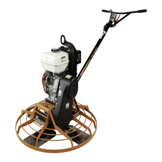
WAL K - B E H I N D H I G H T O R Q U E T R O W E L
MBW, Inc.
250 Hartford Rd • PO Box 440
Slinger, WI 53086-0440
Phone: (262) 644-5234
Fax: (262) 644-5169
Email: mbw@mbw.com
Website: www.mbw.com
MBW Europe Ltd.
Units 2&3 Cochrane Street
Bolton BL3 6BN
England, UK
Phone: +44 (0) 1204 387784
Fax: +44 (0) 1204 387797
Email: saleseurope@mbw.com
Website: mbw-europe.com
L20709.12.23.P
©MBW, Inc. 2023
Printed in the USA
Advertisement
Table of Contents

Related Manuals for MBW F36 Series


Summary of Contents for MBW F36 Series
- Page 1 Power Pitch ....PP10000 WAL K - B E H I N D H I G H T O R Q U E T R O W E L MBW Europe Ltd. MBW, Inc.
-
Page 2: Table Of Contents
TAB L E O F C O N TE N T S SAFETY INFORMATION ....1 Changing Trowel Blades ..... . 8 Setting Tilt Arm Carriage Bolt Height . - Page 3 WARNING CALIFORNIA PROPOSITION 65 WARNING Engine exhaust and some of its constituents and dust produced during the use of this product contain chemicals known in the state of California to cause cancer, birth defects, and other reproductive harm.
-
Page 4: Safety Information
MBW does not by monoxide, a poisonous, odorless, invisible the publication of these precautions, imply or in any way gas. Death or serious illness may result if represent that these are the sum of all dangers present near inhaled. - Page 5 California to cause cancer and birth defects or other reproductive harm. Avoid breathing engine MBW.COM exhaust. Do not operate equipment in confined areas. 21689 For more information go to www.P65Warnings.ca.gov...
-
Page 6: Safety Decals - Ez Pitch/Low Vibration Handle
Start engine at idle only! 12265 WARNING NEVER place foot on guard ring. 12265 22222 21799 WARNING OPERATION OF THIS EQUIPMENT MAY CREATE SPARKS THAT CAN START FIRES AROUND DRY VEGETATION. A SPARK ARRESTER MAY BE REQUIRED. THE OPERATOR SHOULD CONTACT LOCAL FIRE AGENCIES FOR LAWS OR REGULATIONS RELATING TO FIRE PREVENTION 19791... -
Page 7: Specifications
S P E C I F I C ATI O N S F36/4 F46/4 Ring Operating Diameter 37-1/2 in. (95 cm) 46-5/8 in. (121 cm) (Outside Diameter) Blade Sweep Diameter 35.5 in. (90 cm) 46 in. (117 cm) Max. Pan Diameter 36.5 in. -
Page 8: Operation
To increase the pitch, rotate the tilt knob clockwise. function properly. To decrease the pitch, rotate the tilt knob • FUEL SUPPLY - The engines on MBW Power Trowels counterclockwise. require a good grade of unleaded automotive gasoline. See the engine owner’s manual for specific details. -
Page 9: (Standard & Ez Pitch Handle)
Stopping Engine Move handle bar to desired height. Rotate handle height adjustment lever (16) clockwise Move throttle to idle position. to re-tighten. Turn trowel safety switch to “OFF”. If lever (21) is not parallel to handle bar when tight, Close the fuel valve. pull out on lever and rotate lever and release lever when up against handle bar. -
Page 10: Maintenance
Fluid Levels SYSTEM FLUID VOLUME RECOMMENDED OIL Gearbox Oil 21 oz. (620 ml) #680 140wt Sulfur Free (MBW #05700) Engine Refer to engine operator/owner manual Engine Maintenance Engine Speed Refer to the engine owner’s manual for maintenance The engine speed is factory preset according to the intervals and procedures. -
Page 11: Lifting
Fill it Mount the arm to gage #07277 as shown in figure 1. with 21 oz. (620 ml) of MBW Worm Gear Oil (MBW #05700). The oil should be to the bottom of the fill hole when sitting level. - Page 12 Trowels equipped with the MBW Power Pitch handle Slide upper actuator mount rear and upward in slot of system may periodically need adjustment to support bracket (5) until resistance is met, Then achieve full range of blade pitch angle. tighten bolt (14) in end of bracket to hold in place.
-
Page 13: Service
S E R V I C E Assembly and disassembly should be performed by a Service Tools service technician who has been factory trained on MBW equipment. The unit should be clean and free of debris. Part No. Description Pressure washing before disassembly is recommended. -
Page 14: Handle Removal/Installation
shaft until the recess in the worm gear hub is snug 23. Pour one can (21 oz.) of #05700 oil into worm shaft against the retaining ring. opening. Install cap and secure with four flange bolts (29). Torque bolts to 90 in/lbs in an “X” pattern. Press bearings (3) on each end of shaft. -
Page 15: Low Vibration Handle Cable Replacement
Remove socket head screw (31) from slot on right side of handle tube (21). Slide pitch cable assembly out top of tube, guiding threaded end thru cable slide on bottom end of tube. Remove button head screw (30) from shaft adapter (22) to remove cable (6). -
Page 16: Spider Bushing Removal
Remove machine screw (13) securing pin (3) at top of Locate springs under cover and replace with spring actuator. Use screw to remove pull-pin. kit (MBW #20859). Remove machine screw (13) at bottom of actuator Reassemble clutch and mount to trowel. - Page 17 Clutch lubrication portion of the Maintenance section. Gaskets and Seals Replace at every overhaul and teardown. Use MBW gasket and seal kit #05470. Gearbox Oil Replace after the first 50 hours of operation, then every 500 operating hours or yearly.
-
Page 18: Replacement Parts
Their sales engineers are available for professional consultation. If you cannot locate an M-B-W distributor in your area, contact MBW, Inc. or one of our Sales Branches listed below. When ordering replacement parts, be sure to have the following information available: •... -
Page 19: Gearbox Assembly
Gearbox Assembly - 16 -... - Page 20 ITEM PART NO. DESCRIPTION 01243 SEAL, GEAR SHAFT 01244 RETAINING RING, EXTERNAL 01251 BEARING TAPER ROLLER (Includes Bearing & Cup) 01252 BEARING TAPER ROLLER (Includes Bearing & Cup) 01254 KEY, 5/16 SQUARE x 2 lg. 01256 O-RING 01279 RETAINING RING, EXTERNAL 05323 HOUSING, GEARBOX 05326...
-
Page 21: Spider Assembly
Spider Assembly - 18 -... - Page 22 ITEM PART NO. DESCRIPTION 01169 GREASE FITTING, 45 01258 SPRING 01280 SOCKET HEAD SHOULDER SCREW, 3/8” x 3/8” 22731 YOKE PLATE ASM. 05330 PRESSURE PLATE, 4-ARM* 05331 SPIDER, 4-ARM (includes 15)* 05397 BOLT, HOLLOW 05402 COMBINATION BLADE, 8” x 14” 05412 COMBINATION BLADE, 8”...
-
Page 23: Drive Assembly
Drive Assembly - 20 -... - Page 24 ITEM PART NO. DESCRIPTION QTY. 06638 WASHER, 3/8” SPECIAL 06858 KEY, 3/16” SQUARE x 5/8” LONG 19372 LIFT HOOK, COATED 19804 CLIP NUT, 1/4-20 20701 SPACER, ENGINE SHAFT 20702 SPACER, TROWEL GEARBOX 20704 CLUTCH, DRIVE, 40 SERIES 20705 CLUTCH, DRIVEN, 40 SERIES 20706 V-BELT, 40 SERIES CLUTCH, 9-3/8 CENTER 20707...
-
Page 25: Guard Assembly
Guard Assembly - 22 -... - Page 26 ITEM PART NO. DESCRIPTION 15674 ENGINE, HONDA GX270 12887 ENGINE, HONDA GX390 21621 GUARD RING, 36” 22048 GUARD RING, 46” Serial number 1470019 & lower and 1470130 &up. 21337 GUARD RING, 46” Serial number 1470020 thru 1470129. 20703 MOUNTING BAR, ENGINE LOCK WASHER, 3/8, ZP F06LW F06PW...
-
Page 27: Standard Handle Assembly
Standard Handle Assembly - 24 -... - Page 28 ITEM PART NO. DESCRIPTION F36 F46 01291 CABLE TIE 01302 THRUST BEARING 05358 KNOB 05363 BEARING 05365 TILT SHAFT 05381 CABLE ASSEMBLY, (Includes items #27 & #28) 05395 PIVOT PIN 07592 SPLICE TERMINAL 07774 WIRE, SHORTING (63” long) 15991 LOCK WASHER, 1/4” INTERNAL TOOTH 16047 SELF TAP SCREW, 1/4-20 x 1/2 21109...
-
Page 29: Low Vibration Handle Assembly
Low Vibration Handle Assembly - 26 -... - Page 30 ITEM PART NO. DESCRIPTION F36 F46 01291 CABLE TIE 01302 THRUST BEARING 05358 KNOB 05363 BEARING 05365 TILT SHAFT 05381 CABLE ASSEMBLY, (Includes items #36 & #37) 05395 PIVOT PIN 07592 SPLICE TERMINAL 07774 WIRE, SHORTING (63” long) 15991 LOCK WASHER, 1/4” INTERNAL TOOTH 16047 SELF TAP SCREW, 1/4-20 x 1/2 21109...
-
Page 31: Ez Pitch Handle Assembly
EZ Pitch Handle Assembly - 28 -... - Page 32 ITEM PART NO. DESCRIPTION F36 F46 01291 CABLE TIE 05381 CABLE ASSEMBLY, (Includes items #34 & #36) 05395 PIVOT PIN 07592 SPLICE TERMINAL 07774 SHORTING WIRE ASM 15991 LOCK WASHER, 1/4” INTERNAL TOOTH 16040 COMPRESSING SPRING 16078 CLIP BEARING 16081 LEVER ARM 16083 LOCK DOG...
-
Page 33: Power Pitch Actuator & Wiring
Power Pitch Actuator & Wiring - 30 -... - Page 34 ITEM PART NO. DESCRIPTION 01244 RETAINING RING, EXT 22690 PUSH ON CAP, 2.0” 22691 PULL OUT DOWEL PIN, 1/4 22692 ACTUATOR MOUNT, BOTTOM 22693 ACTUATOR SUPPORT BRACKET 22694 SHIELD, ACTUATOR 22698 ACTUATOR MOUNT, TOP 22719 ACTUATOR ASM F02SW WASHER, 3/16 X 7/16 X 18GA F06SW WASHER, 9/16 X 1-3/8 X 12GA F08SW...
-
Page 35: Power Pitch Switch & Battery
Power Pitch Switch & Battery - 32 -... - Page 36 ITEM PART NO. DESCRIPTION 01291 CABLE TIE 12303 TERMINAL PIN 12304 SEAL, CONNECTOR WIRE 12306 CONNECTOR SHROUD 22594 M18 COVER ASM 22596 MOUNT, WIRE JUNCTION 22640 FUSE HOLDER 22641 QUICK CONNECT, .110 22665 SOCKET, TWO WIRE 22684 SPLICE, CLAMP ON, TWO WIRE 22685 SPLICE, CLAMP ON, THREE WIRE 22686...
-
Page 37: Warranty
M-B-W, INC. and MBW EUROPE, LTD. right to adjusts labor rates on a claim by claim basis. ("MBW") to define what is, what is not, and for how long 5.OTHER - IT IS EXPRESSLY AGREED THAT THIS...
Need help?
Do you have a question about the F36 Series and is the answer not in the manual?
Questions and answers