Table of Contents
Advertisement
Quick Links
MBW, Inc.
250 Hartford Rd · PO Box 440
Slinger, WI 53086-0440
Phone: (262) 644-5234
Fax: (262) 644-5169
E-mail: mbw@mbw.com
Website: www.mbw.com
1
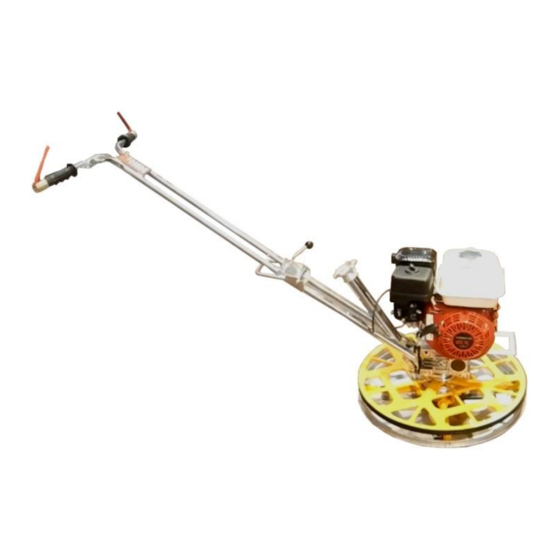
F24 Trowel Machine
MBW (UK) Ltd.
Units 2 & 3 Cochrane
Street
Bolton BL3 6BN, England
Phone: 01204 387784
Fax: 01204 387797
This manul covers the following serial
numbers for each model listed:
F24......................1741219-174999
L18432 / 04.21.F
© MBW, Inc. 2021
Printed in the USA
Advertisement
Table of Contents

Subscribe to Our Youtube Channel
Related Manuals for MBW F24


Summary of Contents for MBW F24
- Page 1 F24 Trowel Machine This manul covers the following serial numbers for each model listed: F24…….……………1741219-174999 MBW, Inc. MBW (UK) Ltd. 250 Hartford Rd · PO Box 440 Units 2 & 3 Cochrane Slinger, WI 53086-0440 Street Phone: (262) 644-5234...
-
Page 2: Table Of Contents
Table of Contents INTRODUCTION ..………………...……………………………………………………..………………..4 EC DECLARATION OF CONFORMITY ................5 GENERAL INFORMATION ....................6 GLOBAL ASPECTS ABOUT SAFETY ....................7 SAFETY SIGNS (PICTOGRAMS ON THE MACHINE) ..............8 SYMBOLS AND GLOSSARY ......................9 SPARE PARTS ORDER ........................10 REVISION OF THE MANUAL ......................10 GENERAL WARRANTY CONDITIONS ................... - Page 3 It is forbidden any reproduction or translation of any part of this manual without prior written notice and authorization by MBW. No part of this publication may be reproduced, stored in a system or transmitted to third parties in...
-
Page 4: Introduction
INTRODUCTION Operation and maintenance manual is an knowledge machine with integral part of the machine: it is necessary information for: • Proper awareness of SAFETY issues. to keep it intact and in a safe place during • The intended use of the MACHINE, the the whole life of the same, even in case of transfer to another user. -
Page 5: Ec Declaration Of Conformity
DECLARATION OF CONFORMITY (Directive 2006/42/EC-Annex IIA) (written in the original language) Name and address of the manufacturer of the machine: BARIKELL S.r.l. Via Razzaboni, 118 41122 Modena (Italy) – Tel. +39 059 31.11.78 – email info@barikell.it Name and address of the company authorized to the draft of technical file: SEMPREANORMA S.r.l. Via Turrini, 17 40012 Calderara di Reno Bologna (Italy) –... -
Page 6: General Information
CHAPTER GENERAL INFORMATION 1.1 Global aspects about safety 1.2 Safety signs 1.3 Symbols and glossary 1.4 Revision of the manual 1.5 Spare parts order 1.6 General warranty conditions... -
Page 7: Global Aspects About Safety
1.1 GLOBAL ASPECTS ABOUT SAFETY by the company that performed the maintenance of the used machine or in Compliance with rules any case in such a way as to jeopardize recommendations contained this its integrity or modify its characteristics, exempts the company itself from any publication allows safe use of the machine and liability concerning the safety of persons appropriate action. -
Page 8: Safety Signs (Pictograms On The Machine)
In case of damage replace them immediately. 1.2 SAFETY SIGNS (PICTOGRAMS ON THE The following safety signs (pictograms) are MACHINE) installed. Residual risks are summarized in It is absolutely necessary to recognize the Chapter 2 PAR. 2.7. meaning of the indications present on the machine and keep their message readable. -
Page 9: Symbols And Glossary
1.3 SYMBOLS AND GLOSSARY expected outcome or impair the safety of the personnel involved; • DANGER: a potential source of injury or damage to health; • MACHINE STATUS, means: • HAZARDOUS AREA: any area inside the mode of operation: automatic gear, and/or near the machine in which the manual operation, shutdown. -
Page 10: Spare Parts Order
Symbols are used in this publication with the For further information we suggest contacting following meaning: the manufacturer. ! IMPORTANT: Indicates important technical Ex.: • information which must not be overlooked. Machine model • Type • Serial number IMPORTANT • Year of build •... -
Page 11: General Warranty Conditions
12 months after the implementation of the parts themselves. 14) Established warranty conditions are binding for all sellers of MBW. Any different 4) For completion of the work required and for agreements will be considered valid only delivery of spare parts the manufacturer upon confirmation in writing by MBW. -
Page 12: Machine Characteristics
CHAPTER MACHINE CHARACTERISTICS 2.1 Identification data of the machine 2.2 Intended use 2.3 Use prohibited 2.4 Technical and dimensional features/noise/vibration/non-ionizing radiation 2.5 Layout/operation and maintenance area/operator position 2.6 General description 2.7 Types of power supply 2.8 Safety measures 2.9 Information on residual risks... -
Page 13: Identification Data Of The Machine
WARNING Do not remove, damage or modify the machine identification data present on it. In the event that data become unreadable immediately contact the manufacturer. 2.2 INTENDED USE 2.1 IDENTIFICATION DATA The trowel machine "Moskito" is meant to MACHINE perform finishing of edges of concrete floor, In order to ensure proper identification of the resin flooring and/or substrates. -
Page 14: Technical And Dimensional Features / Noise / Vibration / Non-Ionizing Radiation
• MANUFACTURER (see PAR. 2.5 of this USE DIFFERENT EQUIPMENT THAN THOSE publication) OR DISOBEY THE DIRECTIONS EXPRESSLY DESIGNATED REGARDING OPERATOR POSITIONING. MANUFACTURER. • LET THE MACHINE TO BE OPERATED BY A NUMBER OF OPERATORS DIFFERENT FROM THAT EXPRESSLY PROVIDED TECHNICAL AND DIMENSIONAL FEATURES / NOISE / VIBRATION / NON- IONIZING RADIATION Measurem... -
Page 15: Operator Positions/Lay-Out/Use And Maintenance Area
2.5 OPERATOR POSITIONS/LAY-OUT/USE AND MAINTENANCE AREA/ 1st level OPERATOR POSITION The power supply is supplied by a an A single operator must work with the unleaded gasoline fuelled engine. machine. He drives the machine by acting on the FUNCTIONAL GROUPS handlebar to move it according to the needs of the processing and performs CONTROL LEVER (STOP) -
Page 16: Types Of Power Supply
900 mm. The machine must be powered by following 2.9 INFORMATION ON RESIDUAL RISKS the instructions given by MBW. For safe operation read the following Despite the application, in the design phase, information carefully:... - Page 17 Reference Signs RISKS Residual Risks Danger Prohibition MECHANICAL + PNEUMATIC It is forbidden to start the machine Inadequate spaces without connecting the float disc to the vanes as indicated in the user manual. ✔ Caught, entrapped, dragged There is a risk of entanglement, pro- hibited use of loose or fluttering cloth- Crushing of upper ✔...
- Page 18 Reference Signs RISKS Residual Risks Danger Prohibition THERMAL Necessary to wait for the Presence of heated ✔ cooling of the engine and surfaces, heat and flames muffler surfaces before conducting maintenance ac- Scalds/burns caused by contacts tivities. Use heat resistant with heated gloves.
- Page 19 Reference Signs RISKS Residual Risks Danger Prohibition RADIATION Not applicable. Ionizing radiation Non-ionizing radiation, heat, light Laser equipment Exposure to Infrared and Ultraviolet Rays DIRECT AND INDIRECT ELECTRICAL Not applicable. Electrocution caused by direct and indirect contacts Electrostatic phenomena Electric arcs Injuries caused by failures in power supply and/or in the...
- Page 20 Refrence Signs RISKS Residual Risks Danger Prohibition FIRE AND EXPLOSION The tank filling operations of ✔ Fire and explosion petrol must be carried out in well ventilated environment Presence of and far from possible sources explosive of heat or flames. athmospheres PHYSICAL WORKING LOAD...
- Page 21 Reference Signs RISKS Residual Risks Danger Prohibition CHEMICAL + BIOLOGICAL The trowel activities must be Injuries caused by carried out in environments with the presence and adequate ventilation. use of stored chemical products The use of protective devices is recommended for the protection of the airways.
-
Page 22: Transport And Lifting
CHAPTER TRANSPORT AND LIFTING 3.1 Packing and unpacking 3.2 Lifting and handling 3.3 Transport 3.4 Storage 3.5 Check for any damage to the machine... -
Page 23: Packing And Unpacking
• United States: A product for each box The operation of packing, handling, transport (fig 3.2) directly entered into the case. and unpacking must only be carried out by qualified personnel with perfect knowledge of FIG.3.2 the equipment to be used and safety rules and regulations. -
Page 24: Transport
in charge of the alerts who must keep WARNING away from the suspended load. The slinging / transport means must take into account the TRANSPORT shape and volume as well as Depending on the country of destination the mass indicated on the plate transport can be made with different media. -
Page 25: Damage Control
• Locate the parts of the machine away ATTENTION from areas subject to humidity or inclement During unloading from the weather; means of transport and placement • Always place between the floor and the of the machine, the maneuvering components of the machine, wooden boards area only accessible... -
Page 26: Machine Installation
CHAPTER MACHINE INSTALLATION 4.1 Installation 4.2 Initial tests 4.3 General safety instructions 4.4 Starting the working cycle 4.5 Trowel drive 4.6 Trowel machine stop 4.7 Restarting the trowel The installation of the machine and the... -
Page 27: Installation
After unloading the machine using a forklift ATTENTION from the means of transport and having Environmental completed the unloading and unpacking operational conditions procedures: should not constitute an obstacle • Place the machine on the floor; to access to the controls of the •... -
Page 28: General Safety Instructions
• Before commanding the start of the WARNING trowel machine the operator must make sure Wear can make the blades of that he is in good stability and has a good point trowel machine sharp of support to avoid sudden movements and enough to generate hazards for the possible loss of control of the machine both operator. -
Page 29: Trowel Drive
• The engine is started at reduced • Close the choke lever (CHOKE); speeds, the clutch has not yet started and the rotor does not rotate yet; • To avoid damaging frictional slippages that could wear it out, firmly place the accelerator at a speed value of 2500 rpm;... -
Page 30: Use Of The Trowel Machine
CHAPTER USE OF THE TROWEL MACHINE 5.1 Surface preparation 5.2 Troweling phase 5.3 Finishing phase... -
Page 31: Surface Preparation
same spot when the concrete is still wet, as 5.1 SURFACE PREPARATION it may cause damage to the flatness of the floor. WARNING Operation of the machine, the user must be aware that moving 5.3 FINISHING PHASE parts are dangerous; therefore, After troweling: to avoid damage, it is important to follow the instructions given in... -
Page 32: Maintenance And Repairs
FIG. 5.1 CHAPTER MAINTENANCE AND REPAIRS 6.1 Scheduled maintenance 6.2 Routine and additional maintenance 6.3 Problems and remedies... -
Page 33: Scheduled Maintenance
Therefore during maintenance check carefully ATTENTION During the execution of the maintenance tasks you must wear the following PPE: CUT RESISTANT GLOVES AND SAFETY SHOES. For certain types of activities (supply of lubricant) make use of airway protective equipment as indicated in the residual risks. Before servicing the machine, make sure you their position and adopt anti-cut gloves. - Page 34 OPERATING MACHINE OPERATION NAME APPOINTEE FREQUENCY INSTRUCTIONS ATUS MECHANICAL PARTS Check the status of the blade bolts. Perform the Check of the tightness daily. If the bolts Machine blades bolts are worn, replace them. Daily stopped/ The bolts can be replaced status and cut energy by a wrench of adequate...
- Page 35 The gear unit housing is sealed to the assembly; if you notice leaks, carefully observe where they come from because there may be leaks from other sources. If the leaks come from the gear box, contact our technical service qualified contractor.
- Page 36 indicated in the or diesel fuel. technical data) Perform this by removing the operation in a well cap. If ventilated area away necessary fill from possible the tank with sources of heat or clean fuel, flames. using a funnel Make use of specific and a filter.
-
Page 37: Routine And Additional Maintenance
Proceed as follows: ROUTINE AND ADDITIONAL • Unhook the blades out of the MAINTENANCE hooking tabs (the tabs on the trowel disc are 2 or 4 depending on the Blades replacement 6.2.1 number of blades), slightly raising the Check the state of wear of the blades machine by leveraging the two hooks or if they have been damaged or bent. -
Page 38: Replacing The Belt
• Remove the oil filler cap and dipstick and clean (Fig. 6.6 a); Replacing the belt 6.2.4 • Reinsert the cap without screw and If, following a visual inspection, it emerges that remove it to check the oil level; the belt is worn or broken, replace it operating •... -
Page 39: Gear Motor Oil Topping Off
Gear motor oil want to proceed with the dismantling of the 6.2.6 various machine parts, you must pay attention topping off to their handling, taking into account the respective masses to be moved. Even in the FIG.6.10 FIG.6.7 case of machines used in the workplace it is necessary to dispose of electrical and electronic products contained in them, if any, according to the regulations in force. -
Page 40: Troubleshooting
TROUBLESHOOTING I S S U E S C A U S E S R E M E D I E S The rotor does not turn at 1. Slow or worn belt 1. Replace belt desired speed 2. Worn clutch 2. -
Page 42: Parts List
PARTS LIST... - Page 47 This page was left blank intentionally No part of this publication may be reproduced, stored in a backup system or transmitted to third parties in any form or by any means, without a written authorization by the Manufac- turer.
Need help?
Do you have a question about the F24 and is the answer not in the manual?
Questions and answers