Table of Contents
Advertisement
Quick Links
Advertisement
Table of Contents
Troubleshooting

Related Manuals for Grozone Control USCO2


Summary of Contents for Grozone Control USCO2
- Page 1 USER GUIDE USCO2 Ultra simple Controller www.grozonecontrol.com...
-
Page 2: Table Of Contents
TABLE OF CONTENTS SAFETY NOTICE PRODUCT DETAILS INSTALLATION & OPERATION CO₂ LEVEL SETTING ALTITUDE SETTINGS CO₂ SENSOR CALIBRATION ERROR CODES QUICK TROUBLESHOOTING GUIDE 10-11 COMPLETE TROUBLESHOOTING GUIDE 12-13 WARRANTY & CUSTOMER SERVICE 14-15... -
Page 3: Safety Notice
SAFETY NOTICE IMPORTANT SAFETY INSTRUCTIONS SAVE THESE INSTRUCTIONS DANGER TO REDUCE THE RISK OF FIRE OR ELECTRIC SHOCK, CAREFULLY FOLLOW THESE INSTRUCTIONS. To reduce the risk of electric shock, disconnect power to the 120V electrical outlet before installing or removing the unit. When removing the electrical wall plate, it may fall across plug pins or become displaced. -
Page 4: Product Details
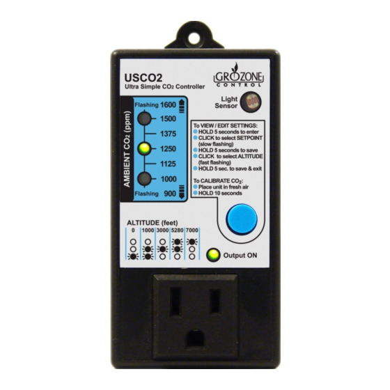
ON and OFF to maintain the CO level between the setpoint and 200 PPM below setpoint. Example: If the setpoint is 1250 PPM, the USCO2 will turn the CO generator at 1050 PPM and will turn it OFF at 1250 PPM. Input/output voltage: 120V. -
Page 5: Installation & Operation
This controller has to be installed on a wall, ideally at the plants canopy, plugged into a 120V electrical outlet. The CO₂ generator or CO₂ bo le is connected to the USCO2 front outlet. Make sure to place your controller at a minimum distance of 4 to 8 feet from the CO generator. - Page 6 INSTALLATION & OPERATION Ambient CO level reading The controller will display up to 7 CO ranges: Approximate CO LED Status PPM Value Over 1600 TOP LED Flashing 1500 TOP LED steady ON 1375 TOP and MIDDLE LED’s steady ON 1250 MIDDLE LED steady ON 1125 MIDDLE and BOTTOM LED’s steady ON...
-
Page 7: Co₂ Level Setting
LEVEL SETTING Press the blue bu on for 5 seconds (less than 10 seconds). · Repeatedly press the blue bu on to select the CO₂ level (refer to the · chart at the Installa on and Opera on sec on), un l the LED is flash- ing at the desired setpoint : 1000 ppm, 1125 ppm, 1250 ppm, 1375 ppm or 1500 ppm. -
Page 8: Altitude Settings
ALTITUDE SETTING * At all me, the al tude se ng must be done right a er the CO level se ng. Repeatedly press the blue bu on to select the al tude level (refer to the · chart below), un l the LED’s are flashing at the desired level. Press and hold the blue bu on for 5 seconds then release it. -
Page 9: Co₂ Sensor Calibration
· automa cally recalibrate itself to 400 PPM. The 3-LED display will flash 4 mes to indicate that the calibra on · was successful and the USCO2 will go back to normal opera on. ERROR CODES Displayed on Descrip on... -
Page 10: Quick Troubleshooting Guide
QUICK TROUBLESHOOTING GUIDE... - Page 11 QUICK TROUBLESHOOTING GUIDE...
-
Page 12: Complete Troubleshooting Guide
COMPLETE TROUBLESHOOTING GUIDE Controller USCO2 1 – Before you start ***IMPORTANT: READ AND FOLLOW THESE INSTRUCTIONS BEFORE STARTING THE TEST. LIGHTING: Perform this test in a room with enough light for the · controller to detect a DAY condi on. A dark loca on should be avoided. - Page 13 COMPLETE TROUBLESHOOTING GUIDE HANDLING AND TEST STEP ITEM EXPECTED RESULTS DESCRIPTIONS Only the bo om LED should be ON or Plug a lamp into the · flashing. The lamp Sensor controller output. should turn ON immediately. The output light Cover the photocell. ·...
-
Page 14: Warranty & Customer Service
WARRANTY & CUSTOMER SERVICE DO YOU HAVE A PROBLEM WITH YOUR CONTROLLER ? PLEASE READ THESE INSTRUCTIONS CAREFULLY AND SAVE THEM FOR FUTURE REFERENCE. 1. I think my controller is damaged, or it simply does not work as indicated in the user guide, what should I do? Please refer to the troubleshoo ng steps. - Page 15 To avoid being charged for the accessories, be sure to include all pieces. Thanks for your coopera on. Any Grozone Control product that is returned with obvious signs of user · neglect will not be covered by the warranty. Grozone Control exercises the right to make final decisions in these ma ers.
- Page 16 Rev. 3.0 www.grozonecontrol.com...
Need help?
Do you have a question about the USCO2 and is the answer not in the manual?
Questions and answers