
Summary of Contents for Safelog TOUCH WIRELESS
- Page 1 SAFELOG TOUCH SAFELOG TOUCH WIRELESS Installations- und Betriebsanleitung Installation and Operating Instruction Notice d’installation et d’utilisation...
- Page 3 Installations- und Betriebsanleitung Installation and Operating Instruction Notice d’installation et d’utilisation...
-
Page 4: Table Of Contents
SAFELOG TOUCH Installation and Operating Manual 1. General Information and Introduction General information Exclusion from liability and warranty Warnings 2. Transport and Storage Product delivery Storage 3. Product Description Equipment Technical data 4. Devices Installation Assembly Electrical connection SAFELOG communication USB connection 5. - Page 5 6.6.3 Function test settings 6.6.4 Settings - operating duration test Menu item "Settings” 6.7.1 Bus circuits 6.7.2 Consumer data 6.7.3 Devices location of SAFELOG 6.7.4 Timers 6.7.5 Inputs/outputs 6.7.6 Actuating consumes (NMM/MM) Menu item "System" 6.8.1 Changing date and time 6.8.2 Devices – Options...
- Page 6 9.1.3 Communication failure 9.1.4 Other failures 9.1.5 SAFELOG device is off Replacing consumers 10. Connection and Programming of External Modules 10.1 External mains fault detection (critical circuit) 10.2 Internal mains fault detection without additional modules 10.3 Connection of external status panel (MFT4)
- Page 7 SAFELOG TOUCH Installation and Operating Manual LIST OF ABBREVIATIONS Consumers Luminaires, line couplers, repeaters, conversion kits and emergen- cy luminaire converters Maintained mode. The luminaire of the consumer is constantly activated Non maintained mode. The luminaire of the connected consumer...
-
Page 8: General Information And Introduction
The instructions refer to our latest model: the SAFELOG TOUCH WIRELESS. Do bear in mind when commissioning the SAFELOG TOUCH that no wireless functions are in place and that they cannot be retrofitted at a later date. -
Page 9: Transport And Storage
transport and storaGe | 9 2. Transport and Storage 2.1 Product delivery On receipt of the device, check that all its contents are on hand and that there is no obvious damage. Report any damage immediately to the forwarder and bear in mind the following: ■... -
Page 10: Product Description
10 | product descrIptIon 3. Product Description The SAFELOG system is for monitoring and controlling safety and exit sign luminaires as well as other SAFELOG-compatible consumers. The SAFELOG TOUCH and the SAFELOG TOUCH WIRELESS have an integrated test log- book according to DIN VDE 0108 10/89, which is saved in the system, but can alternatively be stored on a USB stick with a FAT32 file system. -
Page 11: Equipment
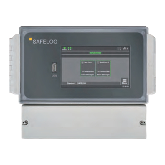
product descrIptIon | 11 3.1 Equipment General ■ 5" multi-touch-capable colour display including a USB port for connecting external storage, a USB printer, a keyboard or a mouse ■ State display of the luminaires through icons and in plain text ■ Automatic commissioning incl. luminaire search, no manual addressing needed of the luminaires ■... -
Page 12: Technical Data
Extra power supply 24V / 40 mA for external modules Ambient temperature 0 °C to 35 °C Safety class Protection class (housing) IP65 Dimensions (W × H × D) 240 x 185 x 112 mm 241.2 68.9 Fig. 1: Dimensional drawing SAFELOG... -
Page 13: Devices Installation
Fig. 2: Opening the housing For the mounting, take on the dimensions of the rear mounting plate of the SAFELOG device. Please note that the wall together with the screws and plugs used need to support the weight of the device. -
Page 14: Electrical Connection
14 | devIces InstallatIon To prevent unauthorised accessing, the SAFELOG device can be provided with a lock at the control panel window. A socket wrench is in the SAFELOG device scope of delivery. 4.2 Electrical connection Fig. 4: View of connecting terminals... -
Page 15: Safelog Communication
■ If line couplers are connected in series, i.e. if additional levels are added, then the max- imum number of levels is 4! For further information, turn to the installation and planning instructions for SAFELOG systems. Wireless systems are always to be commissioned in the following sequence: 1. -
Page 16: Usb Connection
The connection can be used to back up the data, configuration and test logbook. You can, as an option, also connect up a keyboard or mouse. USB sticks need to be of the FAT323 format for use at the SAFELOG device. Fig. 5: USB connection at the display... -
Page 17: System Commissioning
Only qualified and trained electricians are allowed to commission the system. The manual takes you through system commissioning step-by-step. During the commissioning, the SAFELOG device goes through a fixed routine which cannot be aborted by the display. The routine re-starts and entries need to be repeated should the charging current fail during the commissioning. -
Page 18: Switching On The System
Please keep to the following order when switching on the system: 1. Installation all consumers and the main control unit is completed 2. Insert external fuse for the SAFELOG device Step 1: Switching on the SAFELOG device for the first time results in a sequence routine being started for the commission- ing. - Page 19 system commIssIonInG | 19 Step 4: Take up the device number from the rating plate (see Fig 6) when you are requested to enter this number and con- firm with "Enter”. The number is precisely 8 digits in length. Fig. 10: Entering the device number Step 5: The wireless network setup is started with "next”.
- Page 20 20 | system commIssIonInG Following confirmation, the device search- es for all the bus-connected consumers. This can take a few minutes. Fig. 13: Automatic consumer search The as-delivered consumers are not assigned to any ID network. In order to assign the consumers to a main control unit, the main control unit transmits their ID network (INVITE function).
- Page 21 system commIssIonInG | 21 Commissioning of the system is thus concluded. Fig. 16: Start mask For further operations and programming, please read through Chapter 6 of the operating manual.
-
Page 22: Operating And Programming
22 | operatInG and proGrammInG 6. Operating and Programming The SAFELOG device is such that a touch display is used for operating and programming. As an alternative, inputs can follow by way of a USB mouse and/or USB keyboard. Under various menu items you can correct the settings of the data with the arrow keys. -
Page 23: Operating The Display
operatInG and proGrammInG | 23 6.1 Operating the display Fig. 19: Display operating 1. Display: System status 2. Display: Status of the bus circuits 3. Display: Status of the Wireless Bus 4. Display: Wireless data transfer 5. Display: Input - Control inputs 6. Display: Network connection - when connected 7. - Page 24 24 | operatInG and proGrammInG 1. The system status display incorporates the following states: Green System with no faults Yellow System in the battery operation Red System with fault/failure message 2. The display for the bus circuit has 2 messages: Green Consumers in the bus circuit have no failures Red Consumers in the bus circuit with failures Failures in the load circuit are not displayed as failures in the system status.
-
Page 25: Access To The Status Menu
Yellow One or several consumers in the bus circuit in the battery operation Red One or several consumers in the bus circuit are reporting a fault 10. Access to the SAFELOG device main menu. 6.1.1 Access to the status menu The status menu opens when a "bus cir- cuit: X"... - Page 26 26 | operatInG and proGrammInG The colour of the icons in the illustration indicates the state of the consumers. In the battery In the case of a Consumers operation fault Exit sign luminaires Escape route luminaire Repeater line coupler Press the "+/-” zoom keys to enlarge the view or reduced it in size.
-
Page 27: Access To The Main Menu
Fig. 25: Test logbook of consumers 6.1.2 Access to the main menu Step 1: The main menu opens when the "Menu” key on the main display screen is activated. To protect the SAFELOG device from unauthorised interventions, the main menu is password-protected. Fig. 26: Menu Access... - Page 28 You can create your own password in the menu at a later stage. Fig. 27: Menu Enter password Step 3: After entering the password, the main menu of the SAFELOG device opens up. From this menu you can get to all the other sub-items. Fig. 28: Main menu mask...
-
Page 29: Menu Structure Overview
operatInG and proGrammInG | 29 6.1.3 Menu structure overview 6.1 Menu Menu item "Info" 6.2.1 ongoing messages 6.2.2 consumer locations 6.2.3 devices info Menu item "Failure" Menu item "Test logbook" 6.4.1 display test logbook 6.4.2 result of the last f-test 6.4.3 result of the last operating duration test 6.4.4 manual documentation 6.4.5 export test logbook Menu item "Service"... - Page 30 6.7.2.1.7 Actuating consumers 6.7.2.1.8 Group housing 6.7.2.1.9 Starting function test of individual consumers 6.7.2.1.10 Change consumer type (Safety / exit luminaires) 6.7.2.2 Import and export of consumer location 6.7.3 devices location of safeloG 6.7.4 timers 6.7.4.1 Programming sequence 6.7.5 Inputs/outputs 6.7.5.1 Control inputs –...
- Page 31 operatInG and proGrammInG | 31 Menu item "System" 6.8.1 changing date and time 6.8.2 devices - options 6.8.3 network settings 6.8.3.1 DHCP address 6.8.3.2 Change static IP address 6.8.3.3 Change gateway address 6.8.3.4 Subnet 6.8.3.5 Primary DNS 6.8.3.6 Secondary DNS 6.8.4 changing the language 6.8.5 changing system data („Import/export") 6.8.5.1 Reset to delivery status 6.8.5.2 Secure data...
-
Page 32: Menu Item "Info
32 | operatInG and proGrammInG 6.2 Menu item "Info" A general overview is provided in this menu item of the SAFELOG device and the connected consumers. Here you can see all the ongoing system messages, the mounting locations of the consumers and you are provided with an overview of the SAFELOG device status. -
Page 33: Device Info
Fig. 32: "Locations" Detailed view 6.2.3 Device info All important data and state of the SAFELOG device can be seen in this mask. Fig. 33: "Devices info" 6.3 Menu item "Failure” This view displays all the upcoming failure messages and/or faults in plain text. -
Page 34: Menu Item "Test Logbook
34 | operatInG and proGrammInG 6.4 Menu item "Test logbook” In this mask you obtain an insight into all the logged recordings of the system. Here you can document all the work carried out and export all data on a USB stick. Fig. -
Page 35: Result Of The Last B-Test
The data of the last operating duration test is shown here. Fig. 38: "Result of last operating duration test" 6.4.4 Manual documentation The SAFELOG device enables all work car- ried out on the device to be documented in the test logbook: "Maintenance carried out" or "Consumer serviced". -
Page 36: Export Test Logbook
6.4.5 Export test logbook Through the "Export test logbook" mask you can export the data from the SAFELOG device onto a USB stick. Fig. 41: Export test logbook 6.5 Menu item "Service” In this mask you will find the device manu- facturer’s contact data and the appropriate... -
Page 37: Manual Function Test
operatInG and proGrammInG | 37 You can manually start the F-test in this mask. Through the "Function test settings" item, you can also configure the settings for the automatic function test. In the as-delivered state, the "Operating duration test settings" are deactivated and thus not present in the box. - Page 38 38 | operatInG and proGrammInG 6.6.1.2 function test - wireless circuit In this mask you can start a function test on the consumers in the wireless circuit. Fig. 47: Mask "Consumers wireless – Function test" 6.6.1.3 function test of all consumers In this mask you can start a function test of all the consumers connected to the system.
-
Page 39: Manual Operating Duration Test
operatInG and proGrammInG | 39 6.6.2 Manual operating duration test In this mask you can select whether you want to start the manual operating dura- tion test by selecting the individual bus circuits or the groups. Fig. 50: Mask "Scope of test operating duration test"... -
Page 40: Function Test Settings
40 | operatInG and proGrammInG 6.6.2.3 operating duration test - all consumers The "Operating duration test All bus circuits” can be carried out when the system is used as a hybrid system or when consumers are connected in the bus and wireless circuit. -
Page 41: Settings - Operating Duration Test
operatInG and proGrammInG | 41 The time and date for the function test is set in the second mask. It is recommend- ed planning the test in the non-operating periods. The "Save" key concludes the process. The "Back " key gets you to the previous view (without saving). -
Page 42: Bus Circuits
42 | operatInG and proGrammInG This mask has a number of options for programming the connected consumers and the SAFELOG device. Fig. 59: Menu item "Settings" 6.7.1 Bus circuits The functions affecting the individual bus circuits are selected under "Bus circuits". Fig. 60: Mask "Bus circuits"... - Page 43 operatInG and proGrammInG | 43 6.7.1.2 search in the wireless bus The INVITE function is used to find all active consumers in the wireless bus and add them to the wireless network. The scan must be confirmed with "OK". Fig. 62: Mask "Finding in the wireless bus" This can take a few minutes and cannot be interrupted.
-
Page 44: Consumer Data
44 | operatInG and proGrammInG In the following mask you can directly enter the names by way of the indicated keyboard. This is accepted from confirma- tion of the enter key. Fig. 64: Enter bus circuit name 6.7.2 Consumer data To select the individual consumers, select the bus circuit in question from the selec- tion menu. - Page 45 operatInG and proGrammInG | 45 The colour of the icons in the illustration indicates the state of the consumers. In the battery In the case of a Consumers operation fault Exit sign luminaires Escape route luminaire Repeater line coupler Press the "+/-” zoom keys to enlarge the view or reduced it in size.
- Page 46 46 | operatInG and proGrammInG Two overriding functions which are still in the bus circuit can be selected: ■ Clear all consumers in the circuit ■ Change position of the consumers in the circuit 6.7.2.1.1 clearing all consumers in the bus circuit The "Clearing consumers"...
- Page 47 operatInG and proGrammInG | 47 The message signals the fact that the positions of the selected consumers have been changed. Fig. 72: Position indication of the changed con- sumers 6.7.2.1.3 selection of the function To continue with consumer programming, you need to select the function wanted for the programming after selecting the circuits.
- Page 48 48 | operatInG and proGrammInG 6.7.2.1.4 entry of consumer locations Preselect the individual consumers to change their mounting locations. Follow- ing commissioning the consumers are named according to the position in the electrical circuit. Select the corresponding consumer to change its mounting location. Fig.
- Page 49 operatInG and proGrammInG | 49 6.7.2.1.6 finding consumers (nod) The function is for searching and finding individual consumers. To activate the function, select the "Nod on" key. Then the yellow SELF-LED starts to flash at the consumer selected. Fig. 77: Mask "Nod" 6.7.2.1.7 actuate consumers Programming the switch function Non-maintained mode (NMM) / Main- tained mode (MM) of the consumers.
- Page 50 50 | operatInG and proGrammInG To edit, select the consumer wanted and assign it through selection to the group or groups. Press the arrows "▼ /▲ " to select other groups. Confirmation is with the "Save" key. The group must be separately saved for each luminaire before you scroll through the consumers with the arrows "←/→".
- Page 51 operatInG and proGrammInG | 51 6.7.2.1.9 starting function test of individual consumers The F-test of every single consumer can be started in the mask. The F-test at the consumer is set to 5 min. Fig. 82: Mask "F-Test start" 6.7.2.1.10 change consumer type (safety / exit luminaires) The "User type"...
- Page 52 52 | operatInG and proGrammInG 6.7.2.2 Import and export of consumer location SAFELOG can read in the locations as a file and/or back up the configured loca- tions through the export function. The USB interface at the device interchanges the data.
-
Page 53: Devices Location Of Safelog
6.7.3 Devices location of SAFELOG Only "SAFELOG" as the default value stands here as the location. By selecting this menu item you adjust the devices location. Entry is via the keyboard and confirmed with the Enter key. -
Page 54: Inputs/Outputs
– Step selection" The group or the bus circuit to be actuated can be selected with the arrow keys. Only one function can be selected for each timer. 6.7.5 Inputs/outputs The SAFELOG device has the following inputs and outputs. Fig. 91: "Inputs/outputs"... - Page 55 operatInG and proGrammInG | 55 They are: ■ 2 control inputs (24V-230V, AC / DC readily programmable) ■ 3 relay outputs for messages (readily programmable) 6.7.5.1 control inputs – selection You have two inputs available for selection which you can readily programme. They involve non-floating inputs (24V to 230V AC/DC).
- Page 56 ■ Inverting function – reversing function, makes possible actuation when no signal at the entry is on hand 6.7.5.2 relay outputs – selection There are three relay outputs at the SAFELOG device for various messages which can be readily programmed. Fig. 94: Mask "Relay outputs" The function is selected in this mask after selecting the input.
-
Page 57: Actuating Consumes (Nmm/Mm)
The functions can be adjusted with the Selection menu. Several functions on one relay output is possible. 6.7.6 Actuating consumes (NMM/MM) There are a number of possibilities at the SAFELOG device of actuating consumers via the main control unit. The following actuating commands can be carried out: ■ MM on / off ■... -
Page 58: Menu Item "System
You need a separate password for access- ing. In the delivery status it is: "1234". Fig. 99: Password entry under menu item "System" You can undertake settings affecting the SAFELOG device in the mask of menu item "System". Fig. 100: Menu item "System"... -
Page 59: Changing Date And Time
operatInG and proGrammInG | 59 They are the following settings: ■ Date / time ■ Import/Export ■ Devices - options ■ System update ■ Network ■ E-mail ■ Language ■ Change passwords 6.8.1 Changing date and time You can set the date and time with the arrow keys in this mask. -
Page 60: Network Settings
(see Chapter 6.8.3.5) Secondary DNS (see Chapter 6.8.3.6) 6.8.3.1 dHcp address All SAFELOG devices are delivered as standard with the DHCP setting. The soft- ware automatically obtains an IP address from the DHCP server. There is no need for an address to be issued by the network ad- ministrator for integration into the network on hand. - Page 61 6.8.3.2 change static Ip address You can manually allocate an IP address under this menu item if you want to assign a certain address to the SAFELOG device. The specifications for this are obtainable from the operator / network administrator.
- Page 62 62 | operatInG and proGrammInG You can directly enter the address in the SAFELOG device via the keyboard of this mask and save it using the "Enter" key. Fig. 108: Mask "Change gateway address" 6.8.3.4 subnet On changing the static IP address, the physical ( Subnetwork mask) address of the network must be edited.
-
Page 63: Changing The Language
6.8.4 Changing the language You can make a choice between the various languages in this mask. After the language change, the SAFELOG device switches. The texts entered for the loca- tions etc. remain in place. If necessary, manually change the texts. - Page 64 64 | operatInG and proGrammInG 6.8.5.1 reset to factory settings All programmed values and data are cleared and the delivery status default values entered. After activating the key, the system must be placed back into opera- tion. Fig. 114: Mask "Reset to factory settings" 6.8.5.2 data secure All changed values, data and programmes are saved on the USB stick.
- Page 65 Activate the update after renewing the cor- responding data in the SAFELOG device. The function activates the last installed up- date on the SAFELOG device. Not activat- ing the function results in non-acceptance of the replaced data. Fig. 118: Mask "Update activate"...
-
Page 66: Configuration Of E-Mail Settings
If you have received an update for the device software from the manufacturer/supplier of the system, then import the software into the SAFELOG device via this programme item. Apply the following key sequence after reading in and activating the changes in order to transcribe the new values into the SAFELOG device: „Carry out firmware update" ... - Page 67 operatInG and proGrammInG | 67 Enter the name of the recipient of the mail here. Simply remove the e-mail address in this box to clear the recipient. The entry is limited to 40 characters. Fig. 122: Mask "Enter recipient address" Select the messages in this mask which the recipient is to receive.
-
Page 68: Change Password
68 | operatInG and proGrammInG 6.8.6.2 settings for e-mail dispatching Enter the data required for configuring the access in this mask. The data is obtained from your Internet provider or your IT Dept. Fig. 124: Mask "E-mail dispatching" 6.8.7 Change password Any password on hand can be changed in this mask. -
Page 69: Web Visualisation
HTTP via TCP IP: 192.168.110.247 Fig. 126: SAFELOG device and Web visualisation By way of the web interface of the SAFELOG device, a web browser can be used to depict the status information on the system. Connection to the visualisation Connect the SAFELOG device to a local network. -
Page 70: Overall View
70 | WeB vIsualIsatIon 7.1 Overall view Fig. 127: Overall view In the overall view mask you can see the state of the SAFELOG system as opened from the web address. The overview reveals the following information on the SAFELOG device: ■ Device number: Numbering the SAFELOG device is automatically issued by the main control unit ■... -
Page 71: Detailed View
In the delivery status it is: "0000". The password you are inputting here is the same one that you directly entered at the SAFELOG device on accessing the Test menu, Settings and System (see Chapter "Test menu", "Settings" and "System"). -
Page 72: Elements Of The Detailed View
The following elements can be seen throughout in the detailed view and are operable: 1. Back to the overall view: This link takes you back to the overall view. 2. Service link: Link to the contact data of the after-sales service and to the SAFELOG device overall view. -
Page 73: Status Display
7.2.2 Status display Both bus circuits of the SAFELOG device are shown here as well as the logged on con- sumers. Any failures are also shown in the status display. An overview of all consumers is opened by way of "Display consumers" and for the corresponding bus circuits circuit this is shown via the "Test logbook"... -
Page 74: Main Menu
In the delivery status it is: "1234". The password you are inputting here is the same one that you directly entered at the SAFELOG device on accessing the Test menu, Settings and System (see Chapter "Test menu", "Settings" and "System"). - Page 75 vIsualIsatIon | 75 7.2.4 Submenu Each of the main menu items of Info, Test logbook, Test menu, Settings and System have subordinate areas. You can open them by running the mouse across the menu item in question. The areas of the menu items are folded in the normal state: Fig.
-
Page 76: Info
The Info menu item is the automatic home page of the detailed view. A general overview is provided in this menu item of the SAFELOG device and the connected consumers. Here you can see all the ongoing system messages and an overview of the SAFELOG device status (Device info). -
Page 77: Test Logbook
vIsualIsatIon | 77 7.2.7 Test logbook Through this menu item you obtain an insight into all the logged recordings of the system. Here you can also document work carried out and export all data as a CSV file. 7.2.7.1 display test logbook Fig. - Page 78 7.2.7.4 manual documentation Fig. 139: Manual documentation All the work carried out at the SAFELOG device can be documented here in the test log- book: "Maintenance carried out" or "Consumers serviced". The "Consumer serviced" mask allows you to select the corresponding bus circuit and...
-
Page 79: Test Menu
vIsualIsatIon | 79 7.2.7.5 export test logbook Fig. 140: Export test logbook The "Test logbook export" area allows you to export and download all the test logbook entries and messages into a CSV file. 7.2.8 Test menu Through the "Test menu" menu item you can manually start the function test and - by means of the "Function test settings"... - Page 80 80 | WeB vIsualIsatIon 7.2.8.2 manual operating test Fig. 142: Manual operating test By pressing a button here you can manually start a continuous operating test for all cir- cuits or for one bus circuit. You receive an info if the test start is successful. 7.2.8.3 function test settings Fig.
-
Page 81: Settings
7.2.9 Settings Settings gives you a number of options to programme the connected consumers and the SAFELOG device. 7.2.9.1 Bus circuits Fig. 145: Bus circuits You can designate two bus circuits in this area. These names then appear wherever the circuit designations had previously been. - Page 82 82 | WeB vIsualIsatIon Consumer data - Bus circuits 7.2.9.2 Fig. 146: Consumer data - Bus circuits Both bus circuits are listed under consumer data as they are with the status menu. The consumer overview is retrievable by the button showing all the bus circuit consumers. Fig.
- Page 83 vIsualIsatIon | 83 Fig. 148: Overview consumers Fig. 149: Import / Export...
- Page 84 84 | WeB vIsualIsatIon 7.2.9.3 devices location Fig. 150: Devices location You can adjust the devices location in this area. Only "SAFELOG" as the default value stands here as the location. The entry is limited to 12 characters. 7.2.9.4 timers Fig. 151: Timers In this area you can programme various time functions for the system.
- Page 85 vIsualIsatIon | 85 You can edit or activate a timer by clicking the associated button. With the page re-loaded, you are now provided with various setting possibilities for the timer (see 01. in Fig. 149). To deactivate an active timer, click on the button to be edited and select under Function "no function"...
- Page 86 86 | WeB vIsualIsatIon 7.2.9.6 relay outputs – selection Fig. 153: Relay outputs There are three relay outputs at the SAFELOG device for various messages which can be readily programmed in this area. The following functions can be selected: ■ Mains failure ■ Faulty consumer ■...
-
Page 87: System
■ MM on / off ■ NMM off / on 7.2.10 System You can undertake settings affecting the SAFELOG device in the "System" menu. 7.2.10.1 network settings Fig. 155: Network The IP address DHCP, IP address LAN fixed and gateway address are indicated in this area. - Page 88 88 | WeB vIsualIsatIon Password 1 = Accessing the main menu (Level 1 factory settings: "0000”) Password 2 = Accessing the extended settings: Test menu and system settings (Level 2 factory settings: "1234”) Fig. 157: Mask "Devices options" You can activate or deactivate the "Automatic continuous operating test" on this level.
- Page 89 Visualisation | 89 7.2.10.3 E-mail settings Fig. 158: E-mail settings Twelve e-mail addresses can be entered here. A setting can be made for each recipient entered as to the e-mails of which messages are to be sent to the recipient. The following messages can be selected: ■...
-
Page 90: Building Visualisation
Visualisation provides the user with a rapid overview of all consumers connected to the SAFELOG device and of the SAFELOG device itself. You can - at any time - glance over the status of the system and consumers and immediately react in the event of a failure. - Page 91 vIsualIsatIon | 91 7.2.11.1 setting up building visualisation Setting up building visualisation is as follows: ■ Designation of the building layout plan ■ Selection of the building layout plan wanted ■ Upload the layout plan (JPG or PNG format) Fig. 160: Building layout plan - upload A building layout plan can be added through the "Manage building layout plans"...
- Page 92 92 | WeB vIsualIsatIon 7.2.11.2 operating With the "Look at, assign/edit consumers" menu item you can assign consumers and their locations to a building layout plan. Fig. 161: Look at, assign/edit consumers Shown in the building layout plan overview of this menu item are the description, status, information on assigned consumers, location and the editing options.
- Page 93 vIsualIsatIon | 93 Confirmation is then needed for the selected assignment. This then results in the con- sumers being indicated on the building layout plan. In addition, all assigned consumers are listed underneath the building layout plan. Location markings can be cleared there. Fig.
- Page 94 Figure 165 displays a specimen plan with two assigned consumers and the location mark- ing of the SAFELOG device. The assigned consumers are shown underneath the build- ing layout plan. They can be cleared here. The consumers are coloured as in the status display (see Chapter "Elements detailed view", "Status display").
-
Page 95: Maintenance Of The System
The checks are to be logged in the test logbook of the SAFELOG device with both date of the inspection and the result. An automatic testing appliance must comply with ISO 62034. -
Page 96: Weekly Inspections
An automatic testing appliance to be used must comply with EN 62034. Carry out a function test on the SAFELOG device display to examine the switch-over and consumers at the SAFELOG device. -
Page 97: Inspections Every Three Years
The required inspection (operation duration test) is to be done on the SAFELOG device. 8.2.5 Inspections every three years Every 3 years at the latest the illuminance of the emergency lighting is to be tested on the basis of EN 1838. -
Page 98: Appendix
98 | appendIx 9. Appendix 9.1 Fault notifications and failure correction Given that you have problems with the SAFELOG system or the system indicates failures, you can proceed as described in the following sections according to the type of problem/ failure. 9.1.1 Missing consumers The fact of consumers not being found during an automatic search can have various causes. - Page 99 appendIx | 99 Not all consumers are found Are the consumers at Is the cable Mains power Restore supply the end of the bus? broken? supply OK? BUS-voltage at sys- BUS voltage Examine BUS tem OK? Level of 5V short-circuit? present? cable by a bus break Replace elec- (e.g.
-
Page 100: Failure Messages
100 | appendIx 9.1.2 Failure messages The SAFELOG system constantly monitors the connected consumers as to their function both constantly and within the scope of the regularly performed tests. In this context, the following failures can occur, which can in turn be eliminated as described:... -
Page 101: Communication Failure
9.1.3 Communication failure The SAFELOG system monitors communication with the consumers. If it is interrupted, then the failure is reported on at the SAFELOG device. Communication failure One consumer Single consumers or LED status Mains power Restore supply entire group/circuit... -
Page 102: Other Failures
Check whether a jumper has been inserted between "L” and "L´” on the switched to non-maintained luminaire electronics and remove it, if necessary. mode by the SAFELOG system. 9.1.5 SAFELOG device is off If the system does not turn on, first check the mains supply. If the mains supply is OK, the internal fuse may be defective (e.g., due to overvoltage). -
Page 103: Replacing Consumers
4. The new consumer can be installed after removing the defective consumer. 5. This must be followed by a consumer search in the SAFELOG main control unit: > Main menu: Settings / Consumer circuits / Search in Bus circuits / search on the single circuit or in all circuits. -
Page 104: Connection And Programming Of External Modules
104 | connectIon and proGrammInG of external modules 10. Connection and Programming of External Modules 10.1 External mains fault detection (critical circuit) The wiring below indicates Switch input 1 (IN1) with the 24V supply voltage for external modules Fig. 166: External mains monitoring Setting of the system Step 1: ■... -
Page 105: Internal Mains Fault Detection Without Additional Modules
All consumers for self-contained battery have an internal mains fault detector which on the supply voltage failing switches the consumers to the battery operation. The result is simultaneously transmitted to the SAFELOG main control unit. The wiring below indicates Switch 1 (IN1) and Relay output 1 with the 24V supply voltage... - Page 106 106 | connectIon and proGrammInG of external modules 1 2 3 1 2 3 1 2 3 +24V OUT1 OUT2 OUT3 24-230V 24-230V Fig. 167: Internal mains fault detection Setting of the system Step 1: ■ Establish a Group "X" (1-48) which all consumers in the non-maintained mode (NMM) must belong to.
-
Page 107: Connection Of External Status Panel (Mft4)
(NMM). 10.3 Connection of external status panel (MFT4) An external status panel can be connected to the SAFELOG. For this, you can use our MFT4 or an external analogue panel. Clarify the matter of using an external analogue status panel beforehand with your Service partner. - Page 108 108 | connectIon and proGrammInG of external modules Setting the system for the MFT4 Step 1: ■ Select Relay output 1 and choose the "Mains failure" function. (Menu item Settings /Inputs and outputs / Relay functions / Function Relay 1) Step 2: ■...
- Page 109 As of: January 2021 Subject to technical modifications, mistakes, sentence errors, printing errors and printing-induced colour variations. Item No.: 670572-V02...
Need help?
Do you have a question about the TOUCH WIRELESS and is the answer not in the manual?
Questions and answers