Table of Contents
Advertisement
Available languages
Available languages
Quick Links
EN
BLUEDRIVE S
POWER FIN
User's Guide
PF-240S
WARNING
For your own safety and that of your equipment, make sure to take the following precautions. Failure to follow
warning notices and instruction may result in property damage, serious injury or death. Please keep the manual and
read it carefully before using the product; If the manual is lost, please contact our after-sale service center.
Advertisement
Chapters
Table of Contents

Related Manuals for Aqua-Marina BLUEDRIVE S PF-240S

Summary of Contents for Aqua-Marina BLUEDRIVE S PF-240S
- Page 1 BLUEDRIVE S POWER FIN User’s Guide PF-240S WARNING For your own safety and that of your equipment, make sure to take the following precautions. Failure to follow warning notices and instruction may result in property damage, serious injury or death. Please keep the manual and read it carefully before using the product;...
-
Page 2: Table Of Contents
TABLE OF CONTENTS SAFETY WARNING II. MAIN COMPONENTS, PARAMETERS AND OVERALL DIMENSIONS III. PACKING LIST IV. INSTALLATION AND INSTRUCTION V. MAINTENANCE VI. GUIDANCE ON PROBLEMS VII. WARRANTY AND AFTER SERVICE CONTACT INFORMATION... -
Page 3: Safety Warning
Application scope of the product: Any types of SUP boards, kayaks or canoes with slide-in fin base. The electric power fin only provides the power in one-way direction, changing directions requires paddlers’ operation. SAFETY WARNING 1. This product is only for providing power for water leisure products and only limited to be used in water. - Page 4 22. The electric charging port of the control box should be either connected with the power fin, or connected with charger, or cover its lid to avoid short circuit damage caused by other metals or moisture. 23. When the remote control and the charger are not used for a long time, it is necessary to disconnect power supply.
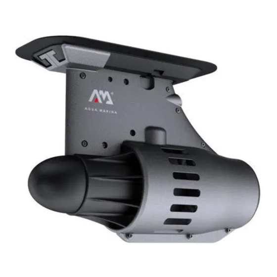
- Page 5 * BLUEDRIVE S Power Fin is compatible with all AM iSUP boards and kayaks with slide-in fin box. * With a US Fin adaptor (optional), the power fin can be also used on any watercrafts with a US FIN box. POWER FIN PRODUCT DETAIL: Metal connector Motor protective...
- Page 6 PARAMETERS Motor Power: 12V DC, 240W Operating Speed: 4-6km/h • Low gear : Max. Speed 4km/h • High gear : Max. Speed 6km/h Underwater Jet Runtime: 1h for low gear, 0.5h for high gear Protective Cover Material: ABS Dimension: 300 x 210 x 110mm (11.8” x 8.3” x 4.3”) Weight: 2.5kg (5.5lbs) Rechargeable Battery Pack: 11.1VDC, 8.8Ah/97.68Wh Special lithium-ion battery for BlueDrive S Power Fin...
- Page 7 OVERALL DIMENSIONS: 210mm 110mm 300mm Overall dimension chart of power fin, 300 x 210x 110mm (11.8" x 8.3" x 4.3") BlueDrive S Power Fin PF-240S DC12V, 240W, IP67 BlueDrive S Power Fin • Do not dispose in fire. Control Box (LBP-12V6S) 155mm Nominal Capacity:...
-
Page 8: Packing List
PACKING LIST Name of component Quantity/ Picture Remark part Unit With power cord, plug, 1 Set Underwater Jet fin base and push-in pin With rechargeable battery, circuit board and 2-in-1 magnetic Control Box ( Include switch (working as 1 Set Li-ion battery pack) both power switch and emergency stop... -
Page 9: Installation And Instruction
INSTALLATION AND INSTRUCTION 1. Open the packing box and check whether the components are complete 2. Install power fin into ISUP (as shown in the picture) 2.1 Insert the bottom of power fin into the fin base of ISUP; 2.2 Insert the slide in push-in pin into the fin base; Insert push-in pin Insert push-in pin * With a US Fin adaptor, the power fin can be also used on any watercrafts with a US FIN... - Page 10 a. Insert the power cord of the charger into the corresponding hole position on the charger to charge the control box. b. Screw off the metal nut on the back of the control box counterclockwise; c. Connect the metal plug on the charger to the corresponding connector on the control box (Please note the direction of convex and concave corresponding position) and tighten the nut;...
- Page 11 5. Remote control 5.1 Please pull out the insulation layer (a transparent sheet) from the remote control before first use. 5.2 Loading the remote control into waterproof sleeve, and put it on the arm (as shown in the following picture) 5.3 Note: For the remote control, the effective distance is under 10 meters.
- Page 12 6. Magnetic Switch Cord 6.1 The magnetic switch cord is a 2-in-1 design, working as both power switch and emergency stop switch. 6.2 For standby mode, snap the magnetic switch in the right position of the control box, and the indicator light will flash blue for 5 times and turn solid blue to display the remaining battery.
- Page 13 8.Storage Guidelines for Control Box 8.1 Do not over-discharge. a. Charge the battery after each use. b. Recharge the battery every six months even if it hasn't been used. c. Over-discharge during storage may damage the battary and reduce its lifetime. 8.2 Storage Temperature 18-25 Recommended storage temperature is 18-25℃.
-
Page 14: Maintenance
MAINTENANCE Maintenance part Time interval Maintenance process If you don't use it for a long time, please Remote control Every month remove the battery; Clean up seaweeds and fishing lines, Underwater jet After each use and use fresh water to wash the jet and dry. -
Page 15: Guidance On Problems
DISPOSAL AND ENVIRONMENTAL PROTECTION This marking indicates this product should not be disposed with other household wastes. To prevent possible harm to the environment or human health from uncontrolled waste disposal, recycle it responsibly to promote the sustainable reuse of material resources. You can obtain information on disposal from your local authorities. -
Page 16: Warranty And After Service Contact Information
WARRANTY AND AFTER SERVICE CONTACT INFORMATION Product warranty is 1 year; and it is not within the scope of the warranty for any modification or use beyond the scope of product use, or any damage caused by wrong operation not in accordance with the manual. AM Official Site AM HOW-TO Guide AM Service Center List... - Page 17 BLUEDRIVE S POWER FIN Guide de l'utilisateur PF-240S AVERTISSEMENT Pour votre propre sécurité et celle de votre équipement, assurez-vous de prendre les précautions suivantes. Si vous ne suivez pas ces avertissements et ces instructions, cela peut entraîner des dommages matériels, des blessures graves ou la mort.
- Page 18 TABLE DES MATIÈRES I. AVERTISSEMENTS DE SÉCURITÉ II. PRINCIPAUX COMPOSANTS, PARAMÈTRES ET DIMENSIONS GÉNÉRALES III. LISTE D’EMBALLAGE IV. INSTALLATION ET INSTRUCTIONS V. MAINTENANCE VI. CONSEILS CONCERNANT LES PROBLÈMES VII. GARANTIE ET INFORMATIONS DE CONTACT APRÈS SERVICE...
- Page 19 Domaine d'application du produit: Tout type de planches SUP, kayaks ou canoës avec base d'aileron coulissant. L’aileron d’alimentation électrique fournit l’alimentation dans un sens, le changement de direction nécessitant la mise en action des pagayeurs AVERTISSEMENT DE DE SÉCURITÉ 1. Ce produit est uniquement destiné à alimenter les produits de loisirs aquatiques et ne doit être utilisé...
- Page 20 service après-vente désigné. 22. Le port de charge électrique du boîtier de commande doit être connecté à l'aileron d'alimentation ou au chargeur et recouvrir son couvercle pour éviter tout court-circuit causé par d'autres métaux ou par l'humidité. 23. Lorsque la télécommande et le chargeur ne sont pas utilisés pendant une longue période de temps, il est nécessaire de débrancher l'alimentation.
- Page 21 * L’aileron d’alimentation (moteur électrique) BLUEDRIVE S est compatible avec toutes les planches et les kayaks AM iSUP avec boîtier d’aileron coulissant. * Avec un adaptateur aileron US (en option), l’aileron d’alimentation (moteur électrique) peut également être utilisé sur tout bateau avec une boîte US FIN DÉTAIL DU PRODUIT AILERON D’ALIMENTATION: Connecteur métallique Couvercle de...
- Page 22 PARAMÈTRES Puissance du moteur: 12V DC, 240W Vitesse de fonctionnement: 4-6km/h • Faible : vitesse: Max. 4km/h • Grande : vitesse: Max. 6km/h Jet sous-marin Durée: 1h en faible vitesse, ½ h en grande vitesse Matériau de protection: ABS Dimensions: 300 x 210 x 110mm (11 8” x 8.3” x 4.3”) Poids: 2.5kg (5.5lb) Batterie rechargeable: 11.1VDC, 8.8Ah/97.68Wh Batterie lithium-ion spéciale pour aileron d’alimentation...
- Page 23 DIMENSIONS GÉNÉRALES: 210mm 110mm 300mm Figures des dimensions globales de l'aileron d’alimentation, 300 x 210x 110mm (11,8" x 8,3" x 4,3") 155mm 282mm 175mm 210mm 610mm Figure des dimensions globales du boîtier Figure des dimensions globales du sac de commande, 210 x 155 x 75mm à...
-
Page 24: Liste D'emballage
LISTE D’EMBALLAGE Quantité N°. Nom de la pièce Image Remarque / Unité Avec cordon d'alimentation, fiche, 1 Jeu Jet sous-marin base d'aileron et broche d’insertion Avec batterie rechargeable, carte de circuit imprimé et interrupteur magnétique Boîtier de commande 2 en 1 (servant à la fois 1 Jeu ( batterie Li-ion d'interrupteur... -
Page 25: Installation Et Instructions
INSTALLATION ET INSTRUCTIONS 1. Ouvrez le carton et vérifiez s’il y a tous les composants 2. Installez l’aileron d'alimentation (moteur électrique) dans l'ISUP (comme indiqué sur l'image) 2.1 Insérez le bas de l'aileron d’alimentation dans la base de l'ISUP; 2.2 Insérez la glissière dans la broche d'insertion dans la base de l'aileron; Insérer la broche d'insertion Insérer la broche d'insertion Avec un adaptateur US Fin, l’aileron d’alimentation peut également être utilisé... - Page 26 a. Insérez le cordon d’alimentation du chargeur à l’emplacement correspondant sur le chargeur pour charger le boîtier de commande. b. Dévissez l’écrou métallique situé à l’arrière du boîtier de commande dans le sens antihoraire; c. Connectez la fiche métallique du chargeur au connecteur correspondant du boîtier de commande (veuillez noter le sens de la position correspondante convexe et concave) et serrez l’écrou;...
- Page 27 5. Télécommande 5.1 Veuillez retirer la couche isolante (une feuille transparente) de la télécommande avant la première utilisation. 5.2 5.2Mettez la télécommande dans le manchon étanche et placez-la sur le bras (comme indiqué dans l'image ci-dessous) 5.3 Remarque: Pour la télécommande, la distance d’utilisation est inférieure à 10 mètres. 5.4 Fonctions de la télécommande: : Démarrer et fonctionner à...
- Page 28 6. Cordon du commutateur magnétique 6.1 Le cordon de l'interrupteur magnétique est un modèle 2 en 1, fonctionnant à la fois comme interrupteur d'alimentation et comme interrupteur d'arrêt d'urgence. 6.2 En mode veille, enclenchez l'interrupteur magnétique à la bonne position du boîtier de commande.
- Page 29 8. Directives pour le stockage du boîtier de commande 8.1 Ne pas trop décharger. a. Chargez la batterie après chaque utilisation. b. Rechargez la batterie tous les six mois, même si elle n'a pas été utilisée. c. Une décharge excessive pendant le stockage peut endommager la batterie et réduire sa durée de vie.
-
Page 30: Maintenance
MAINTENANCE Partie maintenance Intervalle de temps Processus de la maintenance Si vous ne l'utilisez pas pendant une Télécommande Chaque mois longue période de temps, veuillez retirer la batterie. Nettoyez les algues et les lignes de Jet sous-marin Après chaque utilisation pêche et utilisez de l'eau douce pour laver le jet et sécher. -
Page 31: Conseils Concernant Les Problèmes
ÉLIMINATION ET PROTECTION DE L'ENVIRONNEMENT Ce marquage indique que ce produit ne doit pas être éliminé avec les autres déchets ménagers. Pour éviter tout risque d'atteinte à l'environne- ment ou à la santé humaine provenant d'une élimination incontrôlée des déchets, recyclez-le de manière responsable afin de promouvoir la réutilisation durable des ressources matérielles. -
Page 32: Garantie Et Informations De Contact Après Service
GARANTIE ET INFORMATION DE CONTACT APRÈS SERVICE La garantie du produit est de 1 an. Toute modification ou utilisation allant au-delà de l’utilisation du produit, ou tout dommage causé par une mauvaise opération non conforme au manuel n’entre pas dans le cadre de la garantie. Site officiel de AM Guide de AM HOW-TO Liste des centres de service AM... - Page 33 BLUEDRIVE S POWER FIN Benutzerleitfaden PF-240S WARNHINWEIS Beachten Sie zu Ihrer Sicherheit und der Ihrer Ausrüstung die folgenden Vorsichtsmaßnahmen. Die Nichtbeachtung von Warnhinweisen und Anweisungen kann zu Sachschäden, schweren Verletzungen oder zum Tode führen. Bitte bewahren Sie das Handbuch auf und lesen Sie es sorgfältig durch, bevor Sie das Produkt verwenden; Falls das Handbuch abhanden kommt, wenden Sie sich bitte an unser Kundenservice-Center.
- Page 34 INHALTSVERZEICHNIS I. SICHERHEITSHINWEISE II. HAUPTKOMPONENTEN, PARAMETER UND ABMESSUNGEN III. VERPACKUNGSINHALT IV. INSTALLATION UND BEDIENUNG V. WARTUNG VI. FEHLERBEHEBUNG VII. GARANTIE UND KONTAKTINFORMATION DES KUNDENDIENSTES...
- Page 35 Anwendungsbereich des Produkts: Jegliche Arten von SUP-Boards, Kajaks oder Kanus mit Einschub-Finne am Finnenkasten. Die elektrische Power Fin liefert nur Leistung für die Fahrt in eine Richtung, Richtungsänderungen erfordern das Steuern durch den Paddler. SICHERHEITSHINWEIS 1. Dieses Produkt liefert nur Strom für Freizeitprodukte im Wasser und ist ausschließlich auf den Einsatz im Wasser begrenzt.
- Page 36 20. Überprüfen Sie vor jedem Gebrauch, ob eine ausreichende Akkuladung vorhanden ist. 21. Die Power Fin darf nur an SELV (Sicherheitskleinspannung) angeschlossen werden und kann nur mit bestimmten Batterien, Ladegeräten und Fernbedienungen betrieben werden. Falls der Benutzer solche ersetzen muss, kontaktieren Sie bitte das ausgewiesene Kundenservice-Center.
- Page 37 * BLUEDRIVE S Power Fin ist kompatibel mit allen AM iSUP Boards (aufblasbar) und Kajaks mit Finnenkasten für Einschubfinnen. * Mit einem US-Box-Finnenadapter (optional) kann die Power Fin auch an allen Wasserfahrzeugen mit einem US-Box-Finnensystem verwendet werden. PRODUKTDETAILS DER POWER FIN: Metallstecker Schutzab-deckung des Motors...
- Page 38 PARAMETER Motorleistung: 12V DC, 240W Fahrgeschwindigkeit: 4-6 km/h • Niedriger Gang : Max. Höchstgeschwindigkeit 4 km/h • Hoher Gang : Max. Höchstgeschwindigkeit 6 km/h Unterwasserdüse Betriebsdauer: 1 Std. niedriger Gang, 0,5 Std. hoher Gang Schutzhüllenmaterial: ABS Abmessungen: 300 x 210 x 110 mm (11,8 x 8,3 x 4,3 Zoll) Gewicht: 2,5 kg (5,5 lb) Akkupack: 11,1 V DC, 8,8 Ah / 97,68 Wh Spezieller Lithium-Ionen-Akku für Bluedrive S Power Fin...
- Page 39 GESAMTABMESSUNGEN: 210mm 110mm 300mm Abbildung der Gesamtabmessungen der Power Fin, 300 x 210 x 110 mm (11,8 x 8,3 x 4,3 Zoll) BlueDrive S Power Fin PF-240S DC12V, 240W, IP67 BlueDrive S Power Fin • Do not dispose in fire. Control Box (LBP-12V6S) 155mm Nominal Capacity:...
-
Page 40: Verpackungsinhalt
Verpackungsinhalt Bezeichnung der Menge/ Abbildung Anmerkung Komponente Einheit Mit Netzkabel, Stecker, 1 Set Unterwasserdüse Finnenbasis und Einsteck-Stift Mit Akku, Schaltplatte 2-in-1-Magnetschalter Kontrollkästchen (sowohl 1 Set (einschließlich Leistungsschalter und Li-Ionen-Akku) Not-Aus-Schalter) Schwarzes Elastikseil, Schnallen am 1 Set 88 cm mit Karabiner Elastikseil Mit Armbindenhalterung, Fernbedienung und... -
Page 41: Installation Und Bedienung
INSTALLATION UND BEDIENUNG 1. Öffnen Sie die Verpackung und prüfen Sie, ob die Komponenten vollständig enthalten sind 2. Installieren Sie die Power Fin in das ISUP (wie in der Abb. dargestellt) 2.1 Setzen Sie das Unterteil der Power Fin in den Finnenkasten des ISUP ein; 2.2 Setzen Sie den Einschub des Einsteck-Stifts in den Finnenkasten;... - Page 42 a. Um den Akku aufzuladen, stecken Sie zunächst das Ladegerätekabel in den Ladeanschluss am Ladegerät. b. Schrauben Sie die Metallmutter auf der Rückseite des Kontrollkästchen gegen den Uhrzeigersinn ab; c. Schließen Sie den Metallstecker des Ladegeräts am entsprechenden Anschluss am Kontrollkästchen an (bitte beachten Sie die Richtung der entsprechenden konvexen und konkaven Position) und ziehen die Mutter an;...
- Page 43 5. Fernbedienung 5.1 Ziehen Sie bitte vor dem ersten Gebrauch den Isolationsstreifen (transparente Folie) aus der Fernbedienung. 5.2 Einsetzen der Fernbedienung in die wasserdichte Hülle und Befestigung am Arm (wie in der folgenden Abb. dargestellt) 5.3 Hinweis: Für die Fernbedienung beträgt der effektive Bedienabstand unter 10 Meter. 5.4 Bedienung der Fernbedienung: : Inbetriebnahme und Einstellung des niedrigen Gangs : Inbetriebnahme und Einstellung des hohen Gangs...
- Page 44 6. Magnetschalter und Magnetschalterkabel 6.1 Das Magnetschalter ist ein 2-in-1-Design und fungiert sowohl als Leistungsschalter als auch als Not-Aus-Schalter. 6.2 Für den Standby-Modus, setzen Sie den Magnetschalter in die korrekte Position am Batteriekasten und die Anzeigelampe blinkt für 5-mal blau auf und wechselt zur konstanten Anzeige (blau), um den verbleibenden Akkustand anzuzeigen.
- Page 45 8.Richtlinien Für Die Laegung Des Kontrollkästchen 8.1 Vermeiden Sie ein übermäßiges Entladen des Akkus. a. Laden Sie den Akku nach jeder Benutzung auf. b. Laden Sie den Akku alle sechs Monate auf, auch wenn er nicht verwendet wurde. c. Ein übermäßiges Entladen während der Lagerung kann den Akku beschädigen und seine Lebensdauer verringern.
-
Page 46: Wartung
WARTUNG Wartungsteil Zeitintervall Wartungsablauf Falls das Gerät für längere Zeit nicht Fernbedienung Jeden Monat benutzt wird, bitte den Akku entnehmen; Entfernen Sie Algen und Angelschnüre und verwenden Sie frisches Wasser, Unterwasserdüse Nach jeder Verwendung um die Düse zu waschen und zu trocknen. -
Page 47: Fehlerbehebung
ENTSORGUNG UND UMWELTSCHUTZ Dieses Symbol bedeutet, dass dieses Gerät in sämtlichen Mitgliedsstaat- en der EU nicht zusammen mit anderen Haushaltsabfällen entsorgt werden darf. Um mögliche Schäden für die Umwelt oder die menschliche Gesundheit durch unkontrollierte Müllbeseitigung zu verhindern, recyceln Sie es verantwortungsbewusst, um die nachhaltige Wiederverwertung von stofflichen Ressourcen zu fördern. -
Page 48: Garantie Und Kontaktinformation Des Kundendienstes
GARANTIE UND KONTAKTINFORMATION DES KUNDENDIENSTES: Die Produktgarantie beträgt 1 Jahr; der Umfang der Garantieleistung erstreckt sich nicht auf Modifikationen, die Verwendung des Produkts entgegen dem Verwendungszweck bzw. irgendeinen durch Fehlgebrauch verursachten Schaden, gemäß dem Handbuch. AM Offizielle Website AM HOW-TO sanleitung AM Servicecenter-Liste... - Page 49 BLUEDRIVE S POWER FIN Manual de usuario PF-240S ADVERTENCIA Por su propia seguridad y la de su equipo, asegúrese de tomar las siguientes precauciones. El incumplimiento con los avisos, advertencias e instrucciones puede provocar daños en propiedades, lesiones graves o incluso la muerte.
- Page 50 ÍNDICE I. ADVERTENCIA DE SEGURIDAD II. COMPONENTES PRINCIPALES, PARÁMETROS Y DIMENSIONES GENERALES III. LISTA DE EMBALAJE IV. INSTALACIÓN E INSTRUCCIONES V. MANTENIMIENTO VI. ORIENTACIÓN EN CASO DE PROBLEMAS VII. GARANTÍA E INFORMACIÓN DE CONTACTO DEL SERVICIO DE POSVENTA...
- Page 51 Alcance de aplicación del producto: todo tipo de tabla de remo (SUP), kayak o canoa con base para aleta deslizable. La aleta eléctrica brinda únicamente su energía en un sentido, para que cambie de sentido es necesario que el remero la opere.
- Page 52 21. Se brinda la aleta eléctrica únicamente con "separada extra-bajo voltaje" (SELV, por sus siglas en inglés), se le puede aplicar únicamente con las baterías, los cargadores y los controles remotos especificados. En caso que el usuario necesite un reemplazo, deberá ponerse en contacto con el centro de servicios posventa.
- Page 53 * La aleta eléctrica BLUEDRIVE S es compatible con todas las tablas de remo AM iSUP y los kayaks con caja para aleta deslizable. * Con un adaptador para aleta US (opcional), la aleta podrá ser utilizada en cualquier vehículo acuático que tenga caja para aleta US ("US FIN box"). DETALLES DEL PRODUCTO "ALETA ELÉCTRICA": Conector de metal Cubierta protectora...
- Page 54 PARÁMETROS Fuerza de motor: 12V DC, 240W Velocidad de operación: 4-6 km/h • Marcha baja : velocidad máx. 4 km/h • Marcha alta : velocidad máx. 6 km/h Turbina submarina Duración: 1h en marcha baja, 0,5 h en marcha alta Material de la cubierta protectora: ABS Dimensiones: 300 x 210 x 110 mm (11,8”...
- Page 55 DIMENSIONES GENERALES: 210mm 110mm 300mm Ilustración de las dimensiones de la aleta eléctrica, 300 x 210 x 110 mm (11,8" x 8,3" x 4,3") 155mm 282mm 175mm 210mm 610mm Ilustración de las dimensiones del Ilustración de las dimensiones del bolso, caja de control, 610 x 282 x 175 mm (24"...
- Page 56 LISTA DE EMBALAJE Cantidad / N.° Nombre de pieza Foto Observaciones Unidad Con cable, enchufe, 1 equipo Turbina submarina base de aleta y perno a presión Con batería recargable, placa de circuitos e interruptor magnético 2 Caja de control en 1 (opera como 1 equipo (incluye batería interruptor de encendido...
- Page 57 INSTALACIÓN E INSTRUCCIONES 1. Abra la caja del embalaje y compruebe si todos los componentes están dentro. 2. Instale la aleta eléctrica en el ISUP (tal como se muestra en la foto) Inserte el lado inferior de la aleta eléctrica en la base para aleta del ISUP; Inserte el perno a presión deslizable en la base para la aleta;...
- Page 58 a. Inserte el cable de alimentación del cargador en el conector correspondiente del cargador para cargar el caja de control. b. Destornille la tuerca metálica de lado posterior del caja de control, girándola en sentido antihorario. c. Conecte el enchufe metálico del cargador en el conector correspondiente del caja de control (fíjese en la dirección convexa y cóncava de la posición correspondiente) y ajuste la tuerca;...
- Page 59 5. Control remoto 5.1 Antes de utilizar por primera vez, retire la capa aislante (una lámina transparente) del control remoto. 5.2 Sujete el control remoto de la vestimenta impermeable y colóquelo en el brazo (tal como se muestra en la siguiente foto). 5.3 Nota: el rango de operación del control remoto es de unos 10 metros.
- Page 60 6. Cable del interruptor magnético 6.1 El cable del interruptor magnético consiste en un diseño 2 en 1, funcionando como interrup- tor de encendido y también como interruptor de detención de emergencia. 6.2 Para acceder al modo de espera, lleve el interruptor magnético a la posición correcta del caja de control, tras lo cual la luz indicadora parpadeará...
- Page 61 8. Instrucciones de almacenamiento del caja de control 8.1 No descargar en exceso. a. Cargue la batería después de cada uso. b. Recargue la batería cada seis meses, incluso si no ha sido utilizada. c. La descarga excesiva durante el almacenamiento puede dañar la batería y acortar su vida útil.
- Page 62 MANTENIMIENTO Pieza Intervalo Proceso de mantenimiento Si no lo va a usar por un período Control remoto Todos los meses prolongado, retire la pila; Limpie las algas y las líneas de pesca, Turbina submarina Tras cada uso y use agua dulce para lavar el chorro y secar.
- Page 63 DESECHO Y PROTECCIÓN DEL MEDIO AMBIENTE Esta marca indica que no debe desecharse este producto junto con otros residuos domésticos. A fin de prevenir posibles daños al medioam- biente o a la salud humana debido al desecho indiscriminado de residuos, recicle de manera responsable para promover la reutilización de recursos materiales.
- Page 64 GARANTÍA E INFORMACIÓN DE CONTACTO DEL SERVICIO DE POSVENTA La garantía del producto es de 1 año; la garantía no cubre ninguna modificación o uso más allá del alcance del uso indicado del producto ni, asimismo, ningún daño causado por la operación incorrecta que no siga las instrucciones del presente manual.
Need help?
Do you have a question about the BLUEDRIVE S PF-240S and is the answer not in the manual?
Questions and answers