Table of Contents

Related Manuals for Cincinnati CL-900 Series


Summary of Contents for Cincinnati CL-900 Series
- Page 1 OPERATION, SAFETY, AND MAINTENANCE MANUAL CL-900 SERIES LASER SYSTEM 5x10, 6x12, 8x20 FRAME C I N C I N N AT I I N C O R P O R AT E D C I N C I N N A T I , O H I O 4 5 2 1 1 COPYRIGHT ...
- Page 3 MANUAL GUIDE To get the maximum benefit of your new CINCINNATI INCORPORATED machine, read this manual thoroughly and refer to it often for guidance and information. IMPORTANT: Before you operate the machine, read and understand thoroughly, Section 3 on Safety.
-
Page 5: Table Of Contents
SAFETY STANDARDS AND PUBLICATIONS ..........3-2 LASER HAZARD CLASSIFICATION .............3-3 CONTROL MEASURES .................3-4 EXPLANATION OF LASER RADIATION............3-5 LASER TYPES ..................3-5 HAZARDS - CINCINNATI LASER SYSTEMS - FIBER LASER .....3-6 EYE HAZARDS ..................3-6 SKIN HAZARDS ..................3-7 NOMINAL HAZARD ZONES ................3-7 BEAM EXPOSURE CATEGORIES ............3-8 ASSOCIATED HAZARDS ................3-10... - Page 6 TO THE OPERATION MANUAL FOR THE CL-900 LASER SYSTEM...7-1 SECTION 8 OPTIONS FUME BLOWER .....................8-1 BALL TRANSFER LOAD STATION ..............8-1 CINCINNATI MATERIAL HANDLING SYSTEMS ...........8-1 AIR ASSIST GAS FILTER AND DRYER ............8-1 AUTOMATIC NOZZLE CHANGER (ANC) ............8-1 SECTION 9 MAINTENANCE AND ADJUSTMENTS LUBRICATION REQUIREMENTS ..............9-1...
-
Page 7: Introduction
• Quality and type of material CINCINNATI machines are designed to be rugged and durable. However, improper adjustment or lack of maintenance can reduce the quality of parts produced on the machine. The quality of a laser-cut edge depends on the combination of a uniform laser beam of adequate power, properly focused on the workpiece with an adequate supply of the correct assist gas, traveling at a speed compatible with the material removal rate. - Page 8 EM-573 (N-04-18)
-
Page 9: Identification
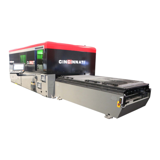
SECTION 1 IDENTIFICATION CINCINNATI CL-900 SERIES LASER SYSTEM - FIBER LASER ENCLOSURE LOAD FRAME OPERATOR DOOR 10. PALLET DOOR LASER STATUS INDICATOR LIGHT 11. SCRAP BIN ACCESS DOOR MATERIAL SUPPORTS 12. OPERATOR CONTROL STATION MATERIAL CLAMPS 13. MAIN FRAME UPPER PALLET 14. - Page 10 GAS AND WATER CONNECTIONS MAIN DISCONNECT ENCLOSURE ACCESS POWER ENCLOSURE ELECTRICAL CONNECTION CONTROL ENCLOSURE Figure 1-2 Rear View EM-573 (N-04-18)
- Page 11 LASER STATUS INDICATOR LIGHTS FIBER LASER E-STOP CONTROL KEY Figure 1-3 nLight Source EM-573 (N-04-18)
- Page 12 ENCLOSURE FIBER LASER E-STOP LASER STATUS INDICATOR LIGHTS KEYSWITCH FIBER LASER MAIN DISCONNECT Figure 1-4 IPG Light Source EM-573 (N-04-18)
- Page 13 ENCLOSURE MAIN DISCONNECT STATUS INDICATOR LIGHTS CAREL CONTROLLER CONTROL SWITCH Figure 1-5 Chiller EM-573 (N-04-18)
- Page 14 X-2 AXIS WAY COVER Z-AXIS FIBER CABLE CARRIER ASSIST GAS PROPORTIONAL VALVES RIGHT GANTRY ENCLOSURE Y-AXIS CABLE CARRIER SCRAP TRAY ASSEMBLY LEFT GANTRY ENCLOSURE Figure 1-6 Rear View of the Gantry FRONT OF THE HEAD TIP ASSEMBLY ALIGNMENT FLAT ON THE TIP ASSEMBLY TIP ASSEMBLY...
- Page 15 BEAM CENTERING ADJUSTERS UPPER COVER GLASS DOOR AIR BLAST ASSIST GAS HOSE COMPLETE TIP ASSEMBLY LOWER COVER GLASS DOOR Z-AXIS CABLE CARRIER Figure 1-8 Y-Plate and Auto Focus Head Assembly EM-573 (N-04-18)
- Page 16 PALLET DOOR REGULATOR REGULATOR FOR SUPPLY MANIFOLD OPERATION STATION RETURN MANIFOLD AIR SUPPLY MANIFOLD ASSIST GAS FILTERS Figure 1-9 Pneumatic Enclosure LENS COOLANT SENSOR ASSIST GAS FILTER Figure 1-10 Y - Plate Manifold EM-573 (N-04-18)
-
Page 17: Installation
The main frame is lifted by using four standard lifting clevises attached to four lifting links (C.I. P/N #920584) with spacers (C.I. P/N #921838). The four lifting links (supplied by CINCINNATI) are attached to the inside of the main frame with 1”-8 UNC SHCS bolts. See Figure 2-1. -
Page 18: Foundation
4. Connect the (customer-furnished) fume exhaust system to the fume duct exit port. 5. Complete preliminary leveling procedure described below. 6. CINCINNATI Service will install the operator control station and complete final electrical connections to the control. 7. Install gas lines, wiring, and hoses as described in the pre-installation manual. -
Page 19: Chiller
Hoses are furnished to connect the chiller when located as shown on the Foundation Plan. If an alternative chiller location is required, consult CINCINNATI INCORPORATED. See Section 4 - SPECIFICATIONS for chiller fluid specifications. LEVELING Main frame leveling adjustments are made using jackscrews provided at the mounting pads. - Page 20 Figure 2-4 Cross Leveling (Preliminary) Figure 2-5 Longitudinal Leveling EM-573 (N-04-18)
-
Page 21: Final Leveling
FINAL LEVELING Final leveling should be done with a CINCINNATI INCORPORATED Service Representative present. The purpose of final leveling is to ensure that the gantry does not rotate about the X-axis as the gantry moves from end-to-end. Excessive rotation will cause laser beam misalignment during operation. Follow these steps for Final Leveling: 1. -
Page 22: Electrical Connection
The machine must be properly grounded in accordance with the National Electric Code NFPA 70, 2008 edition, article 250, sections 50 through 70. Place ground electrode per installation documents. Do not start the machine until Section 3 - SAFETY of this manual has been read thoroughly and a CINCINNATI INCORPORATED Service Representative is present. -
Page 23: Safety
SAFETY SAFETY IS EVERYONE’S JOB The CINCINNATI Laser System - Fiber Laser manufactured by CINCINNATI INCORPORATED has been designed to meet the highest order of reliability and ease of operator use. This system has been certified under Federal Regulations 21 CFR, subpart J, as a Class 4 Laser product as required by the Federal Radiation Control for Health and Safety Act of 1968. -
Page 24: Safety Standards And Publications
Radiation that lacks the energy to deform atoms is called “non-ionizing” radiation. This is the type used in CINCINNATI Laser System - Fiber Laser. The IPG or nLight product is a diode-pumped ytterbium fiber laser. The laser beam is emitted in a continuous wave (CW) at a fixed wavelength of 1.07 micrometers. This wavelength is invisible to the human eye. -
Page 25: Laser Hazard Classification
Laser safety specialists call these limits Maximum Permissible Exposures (MPE’s). The standards and publications listed below will be the most helpful to users of CINCINNATI Laser Systems: 1. ANSI B11.21 “American National Standard for Machines Using Lasers”. - Page 26 Since lasers are not classified on beam access during service, most Class I industrial lasers will consist of a higher class (high power) laser enclosed in a properly interlocked and labeled protective enclosure. In some cases, the enclosure may be a room (walk-in protective housing) which requires a means to prevent operation when operators are inside the room.
-
Page 27: Control Measures
CONTROL MEASURES The CINCINNATI Laser System - Fiber Laser has been designed and manufactured using the highest engineering control measures practical. However, even these high standards have limitations. Laser safety requirements call for administrative and procedural controls to be incorporated in the use of lasers in order to minimize or eliminate the potential of personal injury during laser operation. -
Page 28: Explanation Of Laser Radiation
CINCINNATI Laser System - Fiber Laser uses solid-state diodes to generate the cutting beam. The actual laser- generating unit is located at the end of the CINCINNATI Laser System - Fiber Laser, and the beam is delivered to the cutting head through a fiber optic cable. See Figure 3-2. -
Page 29: Hazards - Cincinnati Laser Systems - Fiber Laser
EYE HAZARDS The beam of a CINCINNATI Laser System - Fiber Laser is a potential eye hazard. If the beam directly or indirectly hits the eye, there is a potential for injury to several different areas, depending upon which eye part absorbs the most radiant energy. -
Page 30: Skin Hazards
Unnecessary exposure of the skin to laser radiation should be avoided regardless of the level of radiant energy. The CINCINNATI Laser System - Fiber Laser has been tested and found to have no detectable x-ray emissions and related hazards. - Page 31 3446 ft. (1051 m) Figure 3-4 Uncontained Beam Hazard Distance The CINCINNATI Laser System - Fiber Laser’s design deals with beam exposure categories in various ways: • Intra-beam (Direct) Exposure occurs when an object is in the beam’s path. The fiber optic cable fully contains the beam to the fiber head.
-
Page 32: Associated Hazards
8000 TABLE 3-2 Nominal Hazard Zone Radius Table 3-2 lists calculated distances for the CINCINNATI Laser System - Fiber Laser. This calculation assumes that the object being hit reflects all of the energy (the worst-case situation). The calculated distance, called the Nominal Hazard Zone Radius in the ANSI Z136.1 standard, was obtained using the method shown in this... -
Page 33: Fumes And Dust
melt nearly all metals and will melt through the bottom of the steel fume box. Hot sparks from the cutting process can be drawn into the fume box initiating this reaction. Fighting this type of fire requires a “Class D” dry powder fire extinguisher. -
Page 34: Gas Storage
determining the nature and composition of the fumes being released. A qualified professional should determine the need and subsequent design of a device to eliminate poisonous emissions from the ventilation exhaust. As mentioned previously, the process generates debris and fine particulate. This material should not be allowed to accumulate in the duct leading to the final exit point or control device. - Page 35 Cylinders should not be stored near elevators, gangways, stairwells, or other places where they can be knocked down or damaged. • Oxygen cylinders should not be stored within 20 ft. (6 m) of cylinders containing flammable gases or near the location of other highly combustible materials. Cylinders are not designed for temperatures in excess of 130°F (54°C).
-
Page 36: Cryogenic Liquid
REGULATORS Pressure regulators must be used on cylinders to maintain a uniform gas supply at the correct pressure. The oxygen regulator should be equipped with a safety relief valve or be so designed that, should the diaphragm rupture, broken parts will be contained. Workers are advised to stand to one side and away from regulator gage faces when opening cylinder valves. -
Page 37: Training
GENERAL SAFETY PRACTICES The properties of cryogenic liquids affect their safe handling and use. • Always handle cryogenic liquids carefully. They can cause frostbite on skin and exposed eye tissue. When spilled, they tend to spread. The vapors emitted by these liquids are also extremely cold and can damage delicate tissues. -
Page 38: Warning (Awareness) Lights
• Do not climb on or between work pallets while DRIVE power is on. Severe injury can result from being trapped between moving pallets. Exercise extreme caution when pallet movement is performed. Remember that when the “Pallets Not Ready” button is not illuminated, the pallets will switch automatically when the cutting program commands the proper code. -
Page 39: Safety Signs
A six- digit number, usually located in the lower right corner, identifies all signs installed on machines by CINCINNATI INCORPORATED. If any of these signs become damaged or defaced, new ones should be ordered by contacting the factory or the nearest CINCINNATI Sales and Service Office. - Page 40 DANGER - LASER RADIATION (830137) This sign is mounted above the cutting head assembly on Z-axis block cover. This sign warns that if the cutting head is removed and the breakaway interlock is defeated, then laser radiation may be present. HIGH STRENGTH MAGNETIC FIELD (921533) This sign warns that a high strength magnetic field is present.
- Page 41 The right side of the sign warns that laser cutting may form poisonous fumes, and that the nature and ventilation of these fumes must be determined. This sign is mounted at three places: one sign is on the operator’s and non-operator’s side of the cut area enclosure and third sign is mounted on the rear of the cut area enclosure.
-
Page 42: Safety Guidelines
SAFETY GUIDELINES SAFETY MAINTENANCE CHECK The following guidelines should be followed to ensure • SAFETY ENCLOSURES operating properly. safety: • ALL service access panels bolted in place. • Safeguarding, such as panel covers, are in place • PINCH POINT guarding properly installed. and working. -
Page 43: Specifications
SECTION 4 SPECIFICATIONS DIMENSIONS WIDTH LENGTH HEIGHT WEIGHT Shipped Installed COMPONENT MODEL Lbs. (mm) (mm) (mm) (mm) (kg) 5 X 10 23,200 (1.5 X 3.0 m) (3175) (4801) (6808) (2540) (10524) 6 X 12 27,200 MAIN FRAME (2.0 X 4.0 m) (3658) (5283) (6807) - Page 44 MAXIMUM MATERIAL THICKNESS FOR CLAMPING: .63 inch (16 mm) The nozzle must be at least 0.80 inches (20 mm) above the material to avoid interference with the clamps. If the nozzle is closer to the material (for example, after cutting), then the program must raise the Z-axis before moving the cutting head near the material clamps.
-
Page 45: Piping Connections
♦ Circuit #2: This circuit services the rest of the machine (linear motors, cutting head, control enclosure, etc.), and should be supplied with distilled water only. ♦ Dowtherm SR-1, is used on machines with Serial numbers 056507 and earlier (except 056455). Please contact Cincinnati Laser service. CHILLER TEMPERATURE SET POINT: ♦ Circuit #1: 71.6°F (22°C) ♦ Circuit #2: 80°F (26.6°C) -
Page 46: Optical Elements
OPTICAL ELEMENTS Fiber Coupling: The fiber optic cable terminates at a quartz block. This quartz block is then mounted in the collimator by a special coupling called the QBH fiber coupling. This coupling has an interlock that only allows the laser beam to be delivered if it is connected to the collimator. - Page 47 Tables 4-2 and 4-3 apply to single orifice nozzles. To estimate assist gas flow for nozzles with more than one orifice, contact CINCINNATI INCORPORATED Laser Applications. Approximate Flow (SCFH) Approximate Flow (SCFH) Nozzle Nozzle Required for Nozzle Orifice Required for Nozzle Orifice...
- Page 48 TABLE 4-4 Nitrogen or Air Assist Gas Supply Pressure Compressed air used for assist gas must meet the following purity specifications at the cutting head: Air Assist Gas Purity Residual Oil < 0.003 PPM by weight, Carryover including vapors < 0.01 micron, Particle 99.999% DOP Carryover...
- Page 49 The very low temperature of cryogenic gas supplies may cause hoses in the Laser System to fail when high assist gas flow rates are used. An external evaporator may reduce this effect. Refer to the gas supplier for additional information. For machines that have the Assist Gas Air Dryer Option, the air supplied at the connection to the machine must meet the purity class of ISO 8573-1:2010 [5:6:4].
-
Page 50: Ambient Temperature
AMBIENT TEMPERATURE 105°F (40°C) maximum 50°F (10°C) minimum Optional equipment modifications are available to extend the ambient temperature limits. Contact CINCINNATI INCORPORATED Laser Technical Services for more information. CAPACITIES Cutting feed rates are determined by material type, thickness, surface condition, required part accuracy, laser power, and proper machine setup. -
Page 51: Setup And Use
In order to accurately represent the Y = zero location along the sheet, these stops are cut by the machine. The following procedures must be completed before the Y = zero stops can be cut: • LASER SETUP, ELECTRICAL (by CINCINNATI Laser Service) specifically setting of Y-axis Home Offset. • LENS CENTERING •... - Page 52 4. The Y = zero machine location will now be checked to be sure the material edge will be under the clamp head. Load “YSTOP.cnc” program to scribe a line across the stop. The YSTOP.cnc program can be edited for scribing with low power and nitrogen assist by changing the cutting parameters.
-
Page 53: And Y-Axis Squareness
X AND Y-AXIS SQUARENESS The CINCINNATI Laser - Fiber Laser gantry has linear encoder feedback on each of the X-axis servo systems. To make the Y-axis travel perpendicular to the X-axis travel, the “home” position of one X-axis encoder is adjusted relative to the other. - Page 54 One piece of mild steel, 10 to 16 gauge (1.5 to 3.5 mm thick), approximately 12 inch x 38 inch (300 x 965 mm) or larger. The following procedures must be completed before the X = zero stops can be set: • LASER SETUP, ELECTRICAL (by CINCINNATI Service), specifically setting of X-axis Home Offset. • BEAM DELIVERY ALIGNMENT •...
- Page 55 3. The position of the X-stop pin is checked by cutting the sheet at a programmed machine location away from pin and measuring the actual distance from the pin surface to the edge of the cut. To accurately interpret the measurement, the kerf width must also be known. First cut a test square or similar test cut out on the sheet (away from the X-stop pin area) and measure the kerf width with a feeler gage.
- Page 56 EM-573 (N-04-18)
-
Page 57: Machine Controls
SECTION 6 MACHINE CONTROLS TOUCHSCREEN KEY CONTROLS FRONT PANEL CONTROLS USB PORT E-STOP TRACKBALL KEYBOARD Figure 6-1 Operator Control Station OPERATOR CONTROL STATION This section describes the individual controls located on the Operator Control Station. Refer to Figures 6-1 through 6-6 for actual component locations. Touchscreen: The touchscreen is a device for monitoring various conditions of the Laser System and selecting various control functions. -
Page 58: Machine Operator Panels
USB Port: On the side of the Operator Control Station is a USB (Universal Serial Bus) port. If a network server is not available, operators can use the USB Port to load or backup programs and process library files. USB flash drives can be purchased from most computer stores. Figure 6-2 Front Panel Controls MACHINE OPERATOR PANEL The Operator Control Station has a front panel with several pushbuttons and indicators, and three keyswitches. -
Page 59: Axis Motion Controls
CYCLE STOP When this button is pushed during automatic operation, axis motion decelerates to pushbutton/indicator: a stop, and all cutting functions such as laser beam and assist gas are turned off. Cycle Stop status is indicated by illumination of this indicator. The indicator will be extinguished when the CYCLE START button is pressed or the control is reset. -
Page 60: Pallet Controls
Y▼ pushbutton/indicator: Same as X◄ pushbutton/ indicator except for Y-axis. RAPID TRAVERSE When the RAPID TRAVERSE button is illuminated, and the X or Y-axis is jogged pushbutton/indicator: from the Machine Operator Front Panel, the jog speed is the value specified by the “X/Y Rapid Jog Speed”... - Page 61 After starting a program, the operator can choose to enable or disable automatic pallet motion by toggling this button ON or OFF before the program reaches the M50 block. If the operator toggles the button OFF before the program reaches the M50 block, the pallets will move when the program commands M50.
- Page 62 Beam Flash - Lens Centering dialog is open. • Program execution is DISABLED. THE HIGH VOLTAGE INTERLOCK KEYSWITCH IS INTENDED FOR USE ONLY BY CINCINNATI OR FACTORY TRAINED SERVICE TECHNICIANS. EMERGENCY STOP Pressing the Emergency Stop pushbutton stops all axis motion, turns off the laser main voltage, and inhibits all cutting functions such as assist gas flow.
-
Page 63: Remote Station
REMOTE STATION The Remote Station is a hand-held control connected by a cable to the main frame. This control allows the operator to use the manual functions described below when performing setup or maintenance. Refer to Figure 6-7. Figure 6-7 Remote Station FEED HOLD This pushbutton has the same function as the CYCLE STOP pushbutton on the Machine pushbutton:... -
Page 64: Load Frame Emergency Stop
EMERGENCY STOP button on the Operator Control Station. FOR ADDITIONAL SETUP AND OPERATIONAL INFORMATION FOR THIS MACHINE, REFER TO EM-574, SECTION 7 - OPERATION, A SUPPLEMENT TO THE OPERATION MANUAL FOR THE CINCINNATI CL-900 SERIES PC CONTROL, INCLUDED WITH THIS MANUAL. -
Page 65: Operation
SECTION 7 OPERATION FOR ADDITIONAL SETUP AND OPERATION INFORMATION FOR THIS MACHINE, REFER TO EM- 574, SECTION 7 - OPERATION, A SUPPLEMENT TO THE OPERATION MANUAL FOR THE CL-900 LASER SYSTEM. EM-573 (N-04-18) - Page 66 EM-573 (N-04-18)
-
Page 67: Options
This system enables fully automated sheet loading integrated with laser operation. A transporter separates the workpiece from a stack of material. The transporter delivers the workpiece to the laser pallet and moves finished nests to a material location. Contact your CINCINNATI INCORPORATED Sales representative for CINCINNATI material handling options and configurations. - Page 68 EM-573 (N-04-18)
-
Page 69: Maintenance And Adjustments
SECTION 9 MAINTENANCE AND ADJUSTMENTS LUBRICATION REQUIREMENTS DRIVES LUBRICATION The X, Y, and Z-axes have “extended lube interval” linear bearings. Lubricate every 2,000,000 feet of X-axis travel, or every six months (2000 hours of operation), whichever occurs first. Figure 9-1 shows the grease manifolds for one side of the X-axis linear bearings. -
Page 70: Z-Axis Lubrication
Do not over-lubricate the bearings. Excess grease could contaminate the encoder scales located near the linear bearing rails. CINCINNATI INCORPORATED requires a grease conforming to the following specifications for X, Y, and Z-axis lubrication: ♦ Kluber Lubrication Isoflex NCA 15 ♦ NLGI #2, worked penetration of 280 mm. -
Page 71: Material Clamp Lubrication
MATERIAL CLAMP LUBRICATION The material clamps located on each pallet should be cleaned and lubricated at least weekly. To clean a clamp, remove the cap screw and clamp hook, then wipe the clamp assembly clean and lubricate with a coat of light oil (Ex. -
Page 72: Scrap Removal
igure 9-5 Adjusting pallet Cable Tension SCRAP REMOVAL The scrap removal system is designed to remove scrap material from the cutting area after processing. The system components are: scraper plates attached to the lower pallet, scrap tray mounted on top of the fume collection plenum, and a scrap cart with removable scrap totes. -
Page 73: Encoder Maintenance
X-axis Read Head optics. Cleaning the Read Head requires disassembly. Consult CINCINNATI Laser Service before removing the Read Head. The X-axis encoder scales are protected by a lacquer coating to help them tolerate handling and contamination. - Page 74 QBH receiver, it is to be inspected for dust, dirt, or damage. Refer to the IPG/nLight manual for proper inspection and cleaning procedure. Follow procedures for optic cleaning using the Cincinnati Optics Handling Kit (C.I. P/N #917261). Special procedures are required to remove the fiber connector from the collimator.
-
Page 75: Replacing The Focus Lens Cartridge
REPLACING THE FOCUS LENS CARTRIDGE To change the focus lens cartridge, it is necessary to remove the tip assembly and manifold block and relocate them to a clean dry surface See Figure 9-7. Figure 9-7 Removing Focus lens cartridge Follow these steps to replace the focus lens cartridge: 1. - Page 76 5. Unthread the tip assembly and remove it from the head. 6. Verify that both o-rings are present in the tip assembly and installed correctly. • There is (1) small o-ring near the threads. • There is (1) large o-ring in the center of the tip assembly. 7.
- Page 77 Figure 9-8 Removing Focus lens cartridge For steps 18 to 20, see Figure 9-8. 18. Verify that all (4) o-rings are present on top of the manifold block and installed correctly. EM-573 (N-04-18)
-
Page 78: Replacing The Lower Cover Glass Drawer
19. Orient the manifold block so: • The alignment holes are in line with the alignment pins in the head. • The electrical connector is aligned properly. 20. Tighten the (3) captive M5 x 80 SHCS securing the manifold block to the head. •... - Page 79 Figure 9-9 Lower Cover Glass ONLY OPEN THE UPPER COVER GLASS DOOR WHEN: • The fiber has been removed. • The upper cover glass experiences a temperature fault. To Replace the Lower Cover Glass Drawer follow these steps See Figure 9-9.: 1.
-
Page 80: Replacing The Cover Glass In The Drawer
DO NOT WIPE OR TOUCH THE GLASS SURFACE. 8. Inspect each side of the new cover glass while shining the LED light from behind the optic. 9. Blow off any dust or loose particles, if necessary. ONLY use clean dry air or nitrogen to blow off the glass surface. 10. -
Page 81: Auto Focus Cutting Head
2. Place the 9 inch X 9 inch lint-free cloth on the work surface. 3. Inspect the top of the used cover glass. If there is damage on the top of the cover glass, there may also be damage to the focus lens. Inspect the focus lens too. - Page 82 • False tip touch or sensor failure alarms. • Frequent need to change cutting parameters. Some water may leak when connecting the lens water lines. Water can contaminate the Auto Focus outer cone and tip retaining nut. After installing the auto focus head, clean the nozzle tip, remove any water. Smoke and fumes from cutting may also leave a conductive residue.
-
Page 83: Auto Focus Troubleshooting
4. Allow the assembly to dry. If you use shop air to dry the head, make sure the air is oil-free, clean, and dry. 5. Install the nozzle tip to the head and calibrate standoff. (Jog the cutting head over the material, open Standoff Calibration window, select Recalibrate, and press CYCLE START.) AUTO FOCUS TROUBLESHOOTING Focus Out-Of-Range Error... - Page 84 Figure 9-14 Nozzle Holder The final weekly check is making sure that the calibration pad is clean in order for the HSS to be as accurate as possible. The calibration pad can be seen in Figure 9-15. Figure 9-15 Calibration pad Every two months, check to make sure each of the holders are still fastened to the motor shaft.
-
Page 85: Air Dryer
The moisture indicator (Item 7 in Figure 9-17) should turn green within 30 minutes of turning on the dryer. If it does not turn green, change the moisture indictor cartridge with C.I. P/N #923067. If the new cartridge still does not turn green, contact CINCINNATI Laser Service for assistance. 9-17... -
Page 86: Preventive Maintenance
7. Clean the enclosure windows. The cut area enclosure windows must be washed with a special cleaner. Certain cleaners can damage the window and cause risk to radiation exposure. Cincinnati specifies that our cleaner (C.I. P/N #917263) be used to clean enclosure windows. -
Page 87: Semi-Annual (2000 Hours) Machine Inspection
X1, X2, and Y-axis magnet tracks (see SEMI-ANNUAL MACHINE INSPECTION, Step 1 and 14). 12. Make note of any machine problems that might require additional attention. Contact CINCINNATI Laser Service for assistance in resolving those problems. - Page 88 cut. This task is also important when the laser system alternates between processing aluminum and steel. Remove excess particulate from the fume plenum. Refer to Associated Hazards in Section 3 - SAFETY for additional information. 5. Manually lubricate the fume fan assembly, if applicable, as described in FUME FAN LUBRICATION in this section.
-
Page 89: Annual Machine Inspection
4. On the air dryer system, check the moisture indicator (Item 8 in Figure 9-13). It should turn green within 30 minutes of turning on the dryer. If it does not turn green, change the moisture indicator cartridge with C.I. P/N #923067. If the new cartridge still does not turn green, contact CINCINNATI Laser Service for assistance. - Page 90 9-22 EM-573 (N-04-18)
-
Page 91: Service And Parts
TECHNICAL TRAINING CINCINNATI INCORPORATED offers a variety of Operator and Maintenance Training Programs to assist our customers in obtaining maximum value from their investment in laser cutting systems. With today’s sophisticated controls, operator knowledge and proficiency have a significant effect on overall productivity. These training programs cover the basics of laser cutting, use of the equipment and controls, as well as procedures performed by operating, maintenance, and service personnel. -
Page 92: Customer Information Center
This service is provided on the CINCINNATI INCORPORATED Internet web site (http://www.e-ci.com). Customers can access the following information: MACHINE INVENTORY AND DOCUMENTATION View a listing of your CINCINNATI INCORPORATED machines and available related documents such as manuals. ORDER STATUS View parts orders placed within the last 90 days and track an order shipped by a specific carrier. - Page 93 10-3 EM-573 (N-04-18)
- Page 94 C I N C I N N AT I I N C O R P O R AT E D C I N C I N N A T I , O H I O 4 5 2 1 1 Is a Registered Trademark of Cincinnati Incorporated.
Need help?
Do you have a question about the CL-900 Series and is the answer not in the manual?
Questions and answers