
Related Manuals for Cincinnati CL-900 Series


Summary of Contents for Cincinnati CL-900 Series
- Page 1 CL-900 SERIES LASER SYSTEM (IPG FIBER LASER RESONATORS - 5x10, 6x12, 8x20 FRAME) C I N C I N N AT I I N C O R P O R AT E D C I N C I N N A T I , O H I O 4 5 2 1 1 COPYRIGHT ...
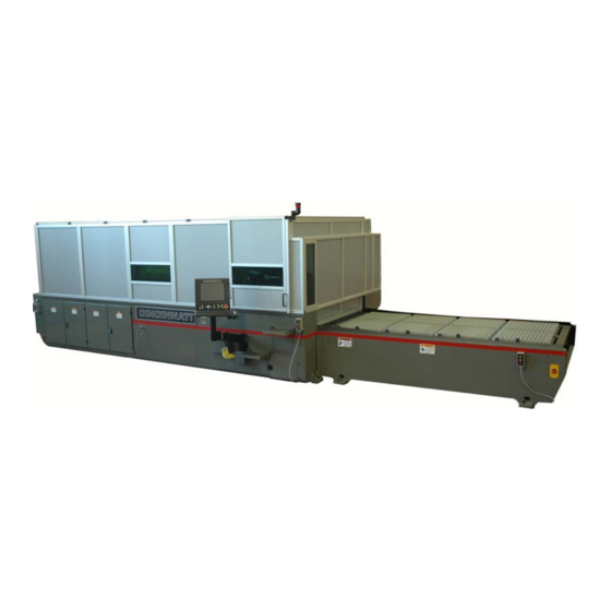
- Page 2 SECTION 1 IDENTIFICATION CINCINNATI CL-900 SERIES LASER SYSTEM - FIBER LASER ENCLOSURE LOAD FRAME OPERATOR DOOR 10. PALLET DOOR LASER STATUS INDICATOR LIGHT 11. REMOTE STATION MATERIAL SUPPORTS 12. SCRAP BIN ACCESS DOOR MATERIAL CLAMPS 13. OPERATOR CONTROL STATION LOWER PALLET 14.
- Page 3 CHILLER MAIN DISCONNECT CHILLER MAIN DISCONNECT MAIN BREAKER INTERLOCK BYPASS KEY GAS AND COOLANT CONNECTIONS POWER ENCLOSURE TRANSFORMER CONTROL ENCLOSURE Figure 1-2 Rear View EM-552 (R-09-16)
- Page 4 I/O ENCLOSURE LASER STATUS INDICATOR LIGHTS DRIVE ENCLOSURE FIBER LASER E-STOP ENCLOSURE FIBER LASER MAIN DISCONNECT Figure 1-3 Rear View EM-552 (R-09-16)
- Page 5 X-2 AXIS WAY COVER Z-AXIS FIBER CABLE CARRIER ASSIST GAS PROPORTIONAL VALVES RIGHT GANTRY ENCLOSURE Y-AXIS CABLE CARRIER SCRAP TRAYS AND SCRAP TRAY CAPS LEFT GANTRY ENCLOSURE Figure 1-4 Rear View of the Gantry EM-552 (R-09-16)
- Page 6 ASSIST GAS HOSE 7.5 INCH LENS DRAWER (EMPTY MANIFOLD SEAL) Z-AXIS MOTOR 5 INCH LENS DRAWER (INSTALLED) AUTO FOCUS HEAD DOOR LOWER TIP ASSEMBLY 10 INCH LENS DRAWER (EMPTY MANIFOLD SEAL) Z-AXIS CABLE CARRIER Figure 1-5 Y-Plate and Auto Focus Head Assembly EM-552 (R-09-16)
- Page 7 PALLET DOOR REGULATOR REGULATOR FOR OPERATION STATION SUPPLY MANIFOLD RETURN MANIFOLD AIR SUPPLY MANIFOLD ASSIST GAS FILTERS Figure 1-6 Pneumatic Enclosure ASSIST GAS FILTER Figure 1-7 Y-Plate Assembly Rear View EM-552 (R-09-16)
-
Page 8: Installation
(C.I. Part # 920584) with spacers (C.I. Part # 921838). The four lifting links (supplied by CINCINNATI) are attached to the inside of the main frame with 1”-8 UNC SHCS bolts. See Figure 2-1. -
Page 9: Installation Of Machine
The customer should prepare 6. CINCINNATI Service will install the operator control the eight anchor locations prior to arrival of the equipment. station and complete final electrical connections to the The eight pads must be pre-leveled to lie in the same plane control. - Page 10 Slotted shims are inserted between the machine foot and FINAL LEVELING steel spacer block as shown on the Foundation Plan drawing. Final leveling should be done with a CINCINNATI After shims are inserted, jackscrews are to be backed off INCORPORATED Service Representative present.
-
Page 11: Precision Level
Figure 2-5 Longitudinal Leveling PLACE SHIMS UNDER END .0005”/Ft OF LEVEL TO PRECISION LEVEL ESTABLISH REFERENCE READING OR PRESS LEVEL INTO PLUMBERS PUTTY TO SECURE AND HOLD LEVEL Y-AXIS IN POSITION. Figure 2-6 Final Leveling with Precision Level EM-552 (R-09-16) -
Page 12: Specifications
SECTION 4 SPECIFICATIONS DIMENSIONS WIDTH LENGTH HEIGHT WEIGHT Shipped Installed COMPONENT MODEL Lbs. (mm) (mm) (mm) (mm) (kg) 5 X 10 23,200 (1.5 X 3.0 m) (3175) (4648) (6808) (2464) (10524) 6 X 12 27,200 MAIN FRAME (2.0 X 4.0 m) (3658) (4648) (6807) - Page 13 9. If these additives are not available, consult each 0 to 240 in. 0 to 98.5 in. CINCINNATI INCORPORATED for approval of a 8 X 20 pallet (0 to 6096 mm) (0 to 2500 mm) comparable product from another supplier.
-
Page 14: Piping Connections
PIPING CONNECTIONS WORKING EFFECTIVE FOCAL LENS (MOUNTING) LENGTH (EFL) LOCATION ASSIST GASES: Three male 9/16 inch-18 straight thread, DISTANCE 37° JIC fittings are supplied for assist gas connections. 5 inch 5 inch (4.85 inch These fittings are threaded into 1/4 inch NPT ports on (Lower) (127 mm) (123.4 mm) - Page 15 Double TABLE 4-2 Oxygen Gas Flow Tables 4-2 and 4-3 apply to single orifice nozzles. To estimate assist gas flow for nozzles with more than one orifice, contact CINCINNATI INCORPORATED Laser Applications. Approximate Flow (SCFH) Nozzle Required for Nozzle Orifice...
- Page 16 Compressed air used for assist gas must meet the following For machines that have the Assist Gas Air Dryer Option, the purity specifications at the cutting head: air supplied at the connection to the machine must meet the purity class of ISO 8573-1:2010 [5:6:4]. See purity class summary below.
-
Page 17: Ambient Temperature
AMBIENT TEMPERATURE 105°F (40°C) maximum 50°F (10°C) minimum Optional equipment modifications are available to extend the ambient temperature limits. Contact CINCINNATI INCORPORATED Laser Technical Services for more information. CAPACITIES Cutting feed rates are determined by material type, thickness, surface condition, required part accuracy, laser power, and proper machine setup. -
Page 18: Machine Controls
SECTION 6 MACHINE CONTROLS Figure 6-1 Operator Control Station OPERATOR CONTROL STATION Keyboard: The keyboard is used to enter alphabetic, numeric, and other characters into the control for program This section describes the individual controls located on and data entry. The keyboard can also be used to open and the Operator Control Station. - Page 19 Figure 6-2 Front Panel Controls USB Connector: On the side of the Operator Control resumes automatic operation. When the control is in Station is a USB (Universal Serial Bus) connector. If a CYCLE STOP mode, the operator can also select the network server is not available, operators can use the USB TRACING function button and then press CYCLE START to begin TRACING mode.
- Page 20 Z UP pushbutton/indicator (+Z): Same as X► AXIS MOTION CONTROLS pushbutton/indicator except for Z-axis. Z DOWN pushbutton/indicator (-Z): Same as X◄ pushbutton except for Z-axis. The Z DOWN indicator will illuminate whenever the Z-axis is moving down; the Z DOWN indicator will also illuminate any time the cutting head is actively tracking the material, using its built-in capacitive sensor.
-
Page 21: Side Panel Controls
After starting a program, the operator can choose to on the Laser System. The indicator is illuminated when enable or disable automatic pallet motion by toggling the drives are enabled. To turn the drives off, turn the this button ON or OFF before the program reaches DRIVES selector switch to LOCK/OFF. -
Page 22: Remote Station
FLASH button is pressed while the Beam Flash - Lens Centering dialog is open. ○ Program execution is DISABLED. NOTE: THE HIGH VOLTAGE INTERLOCK KEYSWITCH IS INTENDED FOR USE ONLY BY CINCINNATI OR IPG SERVICE TECHNICIANS. REMOTE STATION The Remote Station is a hand-held control connected by a Figure 6-7 Remote Station cable to the main frame. - Page 23 TO EM-551, SECTION 7 - OPERATION, SUPPLEMENT TO THE OPERATION MANUAL +/UP pushbutton: Use this pushbutton with the X, Y, FOR THE CINCINNATI CL-900 SERIES PC or Z pushbuttons to jog the X-axis or Y-axis in the CONTROL, INCLUDED WITH THIS MANUAL.
- Page 24 SECTION 8 OPTIONS FUME BLOWER To use the Ball Transfer Load Station, one pallet must be in the cutting position in the main frame and the other must An optional fume blower and motor are available to draw be fully retracted in the load frame. When the pallets are fumes down through the fume plenum so they can be vented in those positions, pressing the BALL TRANSFERS UP away from the work area.
Need help?
Do you have a question about the CL-900 Series and is the answer not in the manual?
Questions and answers