Table of Contents
Advertisement
Quick Links
TE 49
MICROPROCESSOR-BASED
DIGITAL ELECTRONIC TIMER
OPERATING INSTRUCTIONS
Vr. 01 (ENG) - cod.: ISTR 06050
internet : http:\\www.osakaproducts.com
e-mail: support@osakaproducts.com
PREVIOUS STATEMENT:
In this manual are contained all the necessary information for a
correct installation and the instructions for the use and the
maintenance of the product; we recommend, therefore, to read
carefully the following instructions.
The maximum care has been used in the realisation of this
document, anyway OSAKA does not assume any
responsibility deriving from the use of itself.
The same consideration has to be done for each person or
Company involved in the creation of this manual.
The herewith issue is an exclusive property of
which forbids any reproduction and divulgation, although
partial, if not expressly authorised.
OSAKA reserves the right to execute aesthetically and
functional modifications, at any moment and without any notice.
OSAKA - TE 49 - OPERATING INSTRUCTIONS - Vr. 01 - ISTR 06050 - PAG. 1
OSAKA
OSAKA
INDEX
1
INSTRUMENT DESCRIPTION
1.1
GENERAL DESCRIPTION
1.2
FRONT PANEL DESCRIPTION
2
2.1
2.2
2.3
3
3.1
3.2
3.3
3.4
4
4.1
4.2
4.3
4.4
4.5
5
5.1
5.2
6
TROUBLES, MAINTENANCE, WARRANTY
6.1
6.2
7
7.1
7.2
7.3
MECHANICAL DIMENSIONS, PANEL CUT OUT AND
FIXING DEVICE
7.4
7.5
1 - INSTRUMENT DESCRIPTION
1.1 – GENERAL DESCRIPTION
TE 49 is a programmable microprocessor based timer with 1or 2
outputs.
The instrument offers the possibility to program: up to 3 set points
time, 5 operating modes for the output OUT1, 4 operating modes for
the output OUT2, 4 time scales (from 9999 hrs. maximum to 0.1
sec. minimum), 4 functioning modes of counting enable and 2
counting modes (UP or DOWN).
The instrument can have an inside back up battery (optional) which
permits the counting also without power supply.
The counting state is visualised on 4 digits display while the outputs
state is signalised by a led.
The instrument can have 2 outputs (relay or to drive solid state
relays) and 2 digital inputs for count enable (CNT EN) and reset
(RES) which can be for free voltage contacts or voltage signals (the
same voltage supply value).
The programming of the instrument is possible by means of the 3
keys placed on the front while the counting is possible using the
frontal key START/STOP or using the back inputs CNT EN and
RES.
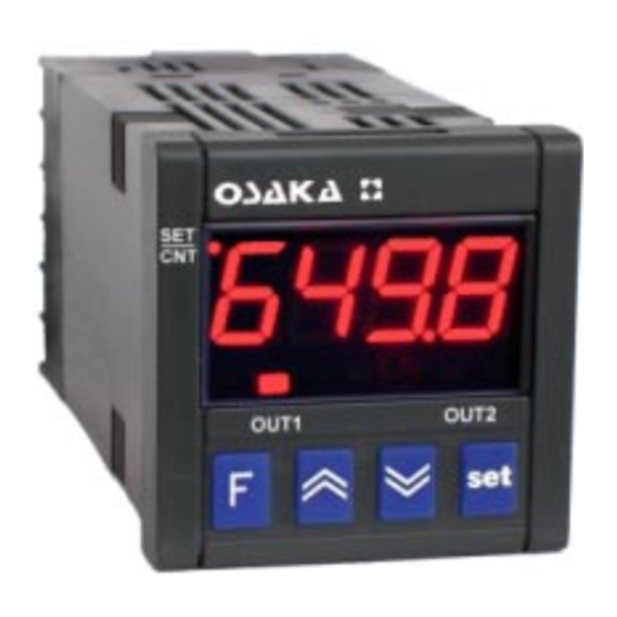
1.2 - FRONT PANEL DESCRIPTION
1 - Key Set : Used for the set point setting and to program the
functioning parameters
Advertisement
Table of Contents

Related Manuals for Osaka TE 49


Summary of Contents for Osaka TE 49
- Page 1 1 - Key Set : Used for the set point setting and to program the functioning parameters OSAKA - TE 49 - OPERATING INSTRUCTIONS - Vr. 01 - ISTR 06050 - PAG. 1...
- Page 2 (lock) which indicates that the parameters are not accessible. animals. Release key Set to exit from this modality. OSAKA - TE 49 - OPERATING INSTRUCTIONS - Vr. 01 - ISTR 06050 - PAG. 2...
- Page 3 When the set time value “t1” has been reached, the instrument enables the output OUT1. The output is disabled by the RESET signal. 4.4 - OUT2 OPERATING MODE OSAKA - TE 49 - OPERATING INSTRUCTIONS - Vr. 01 - ISTR 06050 - PAG. 3...
- Page 4 In the programming mode of the time "t3" the display shows "t3 i" to indicate that the time t3 is independent. If “F2” = 0 the output OUT 2 is always disabled. OSAKA - TE 49 - OPERATING INSTRUCTIONS - Vr. 01 - ISTR 06050 - PAG. 4...
- Page 5 2 most significative figures of the Higher value programmable as Set Point “t1” H2 - HIGH SET POINT TIME t2: Similar to “H1” but referred to the set “t2”. OSAKA - TE 49 - OPERATING INSTRUCTIONS - Vr. 01 - ISTR 06050 - PAG. 5...
- Page 6 Output/s: Up to 2 outputs. Relay SPDT (8 A-AC1, 3 A-AC3 / 250 VAC); or in tension to drive SSR (12VDC/15 mA). Electrical life for relay outputs: 100000 operat. OSAKA - TE 49 - OPERATING INSTRUCTIONS - Vr. 01 - ISTR 06050 - PAG. 6...
- Page 7 O = 12 VDC for SSR - = None e : INTERNAL BATTERY - = Battery not present B = Battery present ff = SPECIAL CODES OSAKA - TE 49 - OPERATING INSTRUCTIONS - Vr. 01 - ISTR 06050 - PAG. 7...
Need help?
Do you have a question about the TE 49 and is the answer not in the manual?
Questions and answers