Table of Contents
Advertisement
Quick Links
Advertisement
Table of Contents

Related Manuals for Prestel MFCP-6

Summary of Contents for Prestel MFCP-6
- Page 1 Prestel MFCP-6 Milti-function control panel USER MANUAL...
- Page 2 Operating Instruction Thank you for purchasing this product. For optimum performance and safety, please read these instructions carefully before connecting, operating or adjusting this product. Please keep this manual for future reference. SURGE PROTECTION DEVICE RECOMMENDED This product contains sensitive electrical components that may be damaged by electrical spikes, surges, electric shock, lightning strikes, etc.
-
Page 3: Table Of Contents
Operating Instruction Table of Contents 1. Features..................4 2. Package Contents..............4 3. Specifications................4 4. Panel Descriptions..............5 5. Connecting and Operating............7 6. Application Diagrams...............7 7. Remote Control Description.............8 8. RS232 Pin Assignment.............8 9. RS232 Control................9 ...............9 9.1 Software Control ..............12 9.2 Command Control 10. -
Page 4: Features
Operating Instruction Dear Customer Thank you for purchasing this product. For optimum performance and safety, please read these instructions carefully before connecting, operating or adjusting this product. Please keep this manual for future reference. 1. Features Work with customized control APP ... -
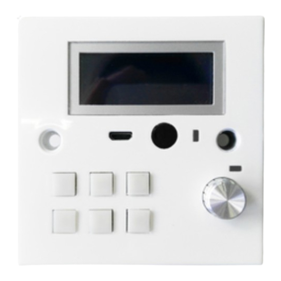
Page 5: Panel Descriptions
Operating Instruction 4. Panel Descriptions ② USB Update ③ Key(Button) ④ IR in ⑤ IR LED ⑥ Knob ⑦ Knob LED ① Ethernet ② IR-TX ③ Relay 1 ④ Relay 2 ⑤ RS232-1. ⑥ RS232-2 ⑦ RS485 ⑧ DC power 24V. - Page 6 Operating Instruction 3.2 USB Driver installation Before connecting the product, you need to copy "STM32 USB transfer serial Port Driver Virtual COM Port Driver (V1.3.1", double-click the software running in the installation package (as shown in figure 1 below), and install the Driver on the computer. 1) The above selection of the computer adaption-driven solution installation as follows.
-
Page 7: Connecting And Operating
Operating Instruction 3) Once again, click the next step, and the computer starts to install the driver. After the installation, the instructions are as follows. 4) After the installation is completed, it will be used as the above prompt to access the device manager to check the correct identification of the device.As shown in the figure below. -
Page 8: Remote Control Description
Operating Instruction 3.3.0 Native mode introduction 1). LCD is divided into two parts, as below picture: A) Left side show the information about the Trigger source and the action of the binding execution. (S= Source; A=Action) ① S: Trigger source. External trigger: including key, infrared reception, RS232 reception, A: Action. -
Page 9: Rs232 Control
Operating Instruction D). Study = Infrared Study Mode 1). Under this mode, the auxiliary mode does not work and cannot be switched 2). Under this mode, the trigger source fails, only the infrared waveform can be captured and the waveform is stored locally. 2). - Page 10 Operating Instruction Auxiliary mode Normal Extend0 Extend1 Studyuse Short/long press RS232 Data length<1024bytes Receive RS485 Data length<1024bytes Receive Trigger source Rotating 20 steps encoder IR Receive Remote control Receive specific protocol data Receive RS232 Send Data length<1024bytes RS485 Send Data length<1024bytes Relay On/off Switchable On/off Switchable...
-
Page 11: Software Control
Operating Instruction K). IP: In lan, device is assigned to IP through DHCP. L). GW: Gateway on the LAN M). MASK: Subnet mask of LAN N). MAC: device's MAC Address O). FONT: Under “RUN” and “CTRL”Model, the font size displayed on the left side.There are 8*6 and 16*8 fonts.Click the rotation encoder to switch, but cannot save to the local, and the default power is 8*6 font size. -
Page 12: Command Control
Operating Instruction 3.3.1 menu bar Open (configuration file): directly import the written configuration file, the ini suffix. save (configuration file): save the current configuration to the location of the software. file save as (configuration file): save the current configuration to another location. Close the program: click to close the program. - Page 13 Operating Instruction IR-IN (Infrared reception): RS232 (232 trigger): RS232 >> RS232-0 / RS-232-1 >> receive command comparison RS485 (485 trigger): RS485 >> RS485-0>>receive instruction comparison RS232 and RS485 trigger include receiving external input and output to external device, when receiving preset trigger command. That is to implement this A series of preset actions under a preset event.
- Page 14 Operating Instruction Trigger source KEY, ENCODE can add any format information, easy to remember. When the trigger source is IR-IN, RS232 and RS485 need to be added according to the format (for example: RS232 receives the data as the character "123" Additional information prefix format to be added asc: 123 or hex hex: 31 32 33) Record trigger source list, number, mode, trigger source, additional information, the width of the text box can be adjusted.
-
Page 15: Web Control
Operating Instruction LED (button light): LED1-6 action module corresponding button 1-6LED light, the action type corresponds to ON / OFF, IR-OUT: In the same way, IR-IN (IR-IN in trigger source is receive instruction and IR-OUT in motion box is send instruction) RS232 (232 action): There RS232_0 and RS232_1 corresponding to the product 1RS232 and 2RS232 terminals, action class Choose to send. - Page 16 Operating Instruction DELAY (delay action): only the number of actions can be written in the action additional information box in ms, such as write 3000, representing 3s delay. BUZZER (buzzer): open, close, add action Additional information in setting the frequency can only enter numbers, enter 1000, on behalf of the setting BUZZER frequency of 1000.
-
Page 17: Warranty Policy
Operating Instruction LCD (screen backlight): You can control the backlight on or off LOOP (Loop): Loop current action list options Specific settings are as follows, 1. Pre-set LOOPStat, action additional signal to add the number of cycles 2. Set the current action required 3. - Page 18 Operating Instruction Remark: You can add any information in additional event information for memory and differentiation. 2). Add event to event list, click to choose the event. 3). Choose LED from Action type, LED1-6 from Action module, Open from Action type.
- Page 19 Operating Instruction *1:You can set LED2-6 following the steps above. *1:If the host can close the port, restart the device. *2 : When download is completed, disconnect the port at the menu, plug out the USB. Conclusion: See testing feedback summarizing at the end of the report. 3.5 Buzzer testings Set the trigger source with a programmer , choose the buzzer as the action, on and off.
- Page 20 Operating Instruction *1:The command should follow fixed format (Eg. If an RS232 command contains “123”, then additional event information should be asc:123 or hex:31 32 33 in hex.) *2:When configuration is completed, click download and send it to device. Conclusion: See testing feedback summarizing at the end of the report. 3.6 RS485 pass through Open device In Tool, Selet Mode “KEY1”...
- Page 21 Operating Instruction 3.7 Relay switch Select any kind, any mod, any event type and any act, you can verify the Relay is On or OFF according to command. 1. COM: Common 2. NC: Normal close 3. NO: Normal open...
- Page 22 Operating Instruction 3.8 IR remote IR study operation: 1. Select “studyuse” In source select mode, change mode from “Normal” to “Study use”. 2. Set Act Tpye “IR0-I OUT” 3. Press the button on the remote controller, device will study and remember IR. 4.
- Page 23 Operating Instruction 4.0 Default configuration / user configuration switching test Configuration mode: LED keylight 1-6 opens User configuration: the parameters are programmed freely with the user. (LED button 1-6 turns off) Switching configuration:switching in 2 modes Verify the above three configurations, whether the parameters change with the mode switch (test with LED keylight as an example) Test conclusion: three kinds of configuration can be switched at any time, and the parameter settings are not interfered with each other...
- Page 24 Operating Instruction Setting steps can refer to the one to one mode The one to multiple control settings are as follows: 1. As host of device ID0: xx(can any number but not 0) ID1: 0(must be 0, Control all other slave machines) 2.
- Page 25 Operating Instruction 5.Click the software "connect" to find the connection, 6.The mainframe power is restarted and the chip size can be found. 7.Click Select the downloaded upgrade file。 8.Click“Update”,The system is beginning to upgrade; 9.After upgrated will have a“Update success”dialog box ,Upgrate success. Noted:①...
- Page 26 Operating Instruction 2.After a period of time, the upper computer is dead. (ten times on the frequency test, two times the computer is dead.) Not reappearing 3.The host computer downloads the configuration complete, closes the connection, the machine key operation is invalid (LCD backlight does not light, no feedback instructions in the event / action list, reboot can be restored) The upper and lower pages are entered before the upper computer is connected.
- Page 27 Operating Instruction MAINTENANCE Clean this unit with a soft, dry cloth. Never use alcohol, paint thinner of benzine to clean this unit. PRODUCT SERVICE (1)Damage requiring service: The unit should be serviced by qualified service personnel if: (a) The DC power supply cord or AC adaptor has been damaged; (b) Objects or liquids have gotten into the unit;...
- Page 28 Operating Instruction installation, set-up adjustments, misadjustment of consumer controls, improper maintenance, power line surge, lightning damage, modification, or service by anyone other than a Factory Service center or other Authorized Servicer, or damage that is attributable to acts of God. 2) THERE ARE NO EXPRESS WARRANTIES EXCEPT AS LISTED UNDER "LIMITED WARRANTY COVERAGE".
Need help?
Do you have a question about the MFCP-6 and is the answer not in the manual?
Questions and answers