Table of Contents
Advertisement
Quick Links
Advertisement
Table of Contents

Related Manuals for IWAKI PUMPS ST-900N

Summary of Contents for IWAKI PUMPS ST-900N
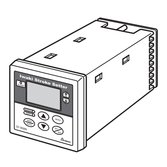
- Page 1 Iwaki Stroke setter ST-900N Instruction manual Thank you for choosing our product. Please read through this instruction manual before use. This instruction manual describes important precautions and instruc- tions for the product. Always keep it on hand for quick reference.
-
Page 2: Order Confirmation
Check if the delivery is correct. Check the nameplate to see if the information such as model codes is as ordered. b. Check accessories are complete. Iwaki Stroke setter ST-900N ki E.E . Pos itio ner ALARM... -
Page 3: Table Of Contents
Contents Order confirmation ............................2 Safety instructions ..............5 Warnings ................................ 6 Cautions ................................. 7 Precautions for use ............................8 Overview ..................9 Introduction ..............................9 Operating principle ............................. 9 Features ..............................9 Operational functions ..........................10 Manual mode ............................10 Real-time SL adjustment ........................ - Page 4 Frame ground ............................19 Electric servo unit ..........................19 Remote/Local control .......................... 19 Terminal assignment for the servo unit ....................19 Power voltage/Earthing ..........................20 Electric servo unit ............................. 21 Measures against noise ........................... 21 Operation ................. 22 Before operation ............................22 Points to be checked ..........................22 Calibration ..............................
-
Page 5: Safety Instructions
Safety instructions Read through this section before use. This section describes important information for you to prevent personal injury or property damage. ■ Symbols In this instruction manual, the degree of risk caused by incorrect use is noted with the follow- ing symbols. -
Page 6: Warnings
WARNINGS Turn off power before service Risk of electrical shock. Be sure to turn off power to stop this product and related devices before service is performed. Turning off power Stop operation If you notice any abnormal or dangerous conditions, suspend operation immediately and inspect/solve problems. -
Page 7: Cautions
CAUTIONS Install a GFCI (earth leakage breaker) An electrical failure of this product may adversely affect other devices on the same line. Purchase and install a GFCI (earth leakage breaker) sepa- Electrical shock rately. Do not install/store this product: • In a flammable atmosphere. •... -
Page 8: Precautions For Use
Precautions for use • Electrical work should be performed by a qualified electrician. Otherwise, personal injury or property damage may result. Caution • Do not install this product: –In a flammable atmosphere. –In a dusty/humid place. –In direct sunlight or wind & rain. –Where ambient temperature can exceed 50ºC or falls below 0ºC. -
Page 9: Overview
Operating principle An Iwaki ST-900N stroke setter is designed for use with the Iwaki AX metering pumps with a servo unit. The setter controls the stroke length of the AX pumps in proportion to 4-20mADC or 1-5VDC signal from user's controller (proportional control). -
Page 10: Operational Functions
Operational functions Manual mode ■ Real-time SL adjustment Use the UP and DOWN keys to change a stroke length in operation (MAN mode). Stroke length changes only while either key is pressed. The "INC" LED lights when the stroke length extends and the "DEC" LED lights when the stroke length retracts. -
Page 11: Adjustment/Correction Functions
Adjustment/Correction functions ■ Stroke length cognition Give the ST setter the 0% and 100% stroke length positions through keypad operation. See page 25 for detail. The setter automatically behaves to store the positions. Perform stroke length cognition every time the setter is used with a unrecognized AX pump, the electric servo unit is repaired, or a displayed stroke length differs from the actual length. -
Page 12: Control Functions (Auto Mode)
Control functions (Auto mode) ■ Inversely proportional line With this setting "ON", the ST setter controls the stroke length inversely proportional to the 4-20mA(/1-5V) signal from a user controller. See page 27 for detailed procedure. Use this function along with the proportional line programming below as necessary (e.g. -
Page 13: Upper/Lower Limit Setting
■ Upper/Lower limit setting Set the upper or lower limit of the proportional line in between 0 and 100%. See page 32 for detail. The up- per limit is provided to control the discharge pressure not to exceed the piping limit pressure. The lower limit is provided to keep the minimum flow rate at any signal current/voltage (user controller). -
Page 14: Part Names
MANUAL MENU is decreasing. AUTO LED AUTO Lights in green during operation in AUTO mode. AUTO ST-900N MAN/AUTO key Menu key Used for changing between the MAN Used for going forward/back and AUTO modes to the main menu. UP/DOWN keys... -
Page 15: Basic Display
■ Basic displays Display MAN/AUTO LED INC/DEC LED ALARM LED Conditions MAN LED lights The ST is in Manual green. mode. INC or DEC LED MAN or AUTO LED The ST increases/ lights during incre- lights depending on decreases the pump ment/decrement of operating mode. -
Page 16: Identification Codes
Identification codes Each code represents the following information. Setter ST - 900N a. Series name b. Series code 900N c. Special version No code : Standard models : Customized models Identification codes... -
Page 17: Installation
First insert the setter into the cutout. e. Attach the mounting hardware to the ST setter and fix to the panel. Iwaki Stroke Setter ALARM MANUAL MENU AUTO AUTO ST-900N 33 or more Panel cutouts dimension Panel (thickness: 1.5-5mm) Mounting hole Mounting hardware Setter mounting... -
Page 18: Wiring
• Check that power voltage is turned off. The ST setter is still charged right after turning off power. Wait for one minute before wiring. ST-900N Remove the terminal cover. Terminal cover Connect the power, earth and signal wires to the ST setter. -
Page 19: End Terminals
End terminals Observe the electric diagram shown on the terminal cover at the back of the ST-900N enclosure. Use M3 screws to fix each wire connection. ■ Input signal (4-20mA/1-5V) Connect the lead wires from user's controller to the terminal pin 17(+) and 18(-). Input resistance is 75Ω... -
Page 20: Power Voltage/Earthing
Power voltage/Earthing Points to be checked • Check that power voltage is turned off. Connect power cable via crimp contacts. Earth the pumps. NOTE • Do not share a power source with a high power device which may generate surge voltage. Otherwise an elec- tronic circuit may fail. -
Page 21: Electric Servo Unit
Electric servo unit Connect wires via bell mouths to respective terminals according to terminal codes. Do not tense wires by exter- nal force. Always use suitable wring tools for wiring. Observe local electric codes. Points to be observed • The servo motor may suffer an overload if the pump motor is turned off first. To avoid overloading, use a PLC or sequencer to turn off either the ST setter or the servo unit, or just to stop the control signal (terminal pin 15 and 16) as turning off a pump motor. -
Page 22: Operation
Operation This section describes setter operation and programming. Run the pump with the ST setter after pipework and wiring is completed. Before operation First check piping and wiring are correct. And then make commissioning before starting op- eration. Points to be checked Before operation, check if... -
Page 23: Operation Programming
Operation programming Operation at each mode is individually set and controlled by keypad operation. Select a prop- er mode to make optimal operation. Mode Parameters Setting ranges Factory default Operation MAN (SL adjustment/Target SL) /AUTO MANUAL (SL adjustment) Inversely propor- ON/OFF tional line 4-20mA... -
Page 24: Programming Flow
Programming flow * The ST setter enters the MAN mode when turning on power with a default setting. Local control 3 sec Keypad lock (P35) Control switching Man mode (P38) Auto mode (P37) No voltage contact/ Open collector signal Remote control (P35) (AUTO mode only) Menu mode SL cognition(P25) -
Page 25: Menu Mode
Menu mode Change the default setting as necessary. Always push the SET/ENT key to enter the new setting. Or push the MENU key to cancel. ■ Stroke length cognition Give the ST setter the 0% and 100% stroke length positions. Stroke length cognition is required every time the ST setter is used with a unrecognized AX pump, the electric servo unit is repaired, or the displayed stroke length differs from the actual length. -
Page 26: Input Current/Voltage Correction
■ Input current/voltage correction The ST setter can correct its reading at 4mA(/1V) and 20mA(/5V) according to the signal current/voltage from a user controller to the terminal pin 17(+) and 18(-). Take the following steps every time a user controller is changed or the input is switched between signal current and signal voltage. -
Page 27: Inversely Proportional Line Selection
■ Inversely proportional line selection Follow the procedure below to control the stroke length inversely proportional to 4-20mA(/1-5V) input. This set- ting is available only in Auto mode. Proportional line (with "off") Inversely proportional line (with "on") Stroke Stroke length length (mA) (mA) -
Page 28: Proportional Line Programming
■ Proportional line programming The default setting proportional line of 4-20mA(0-100%) can be changed by means of proportional band set- ting ("P.B."), Current-Stroke setting ("2P" and "I.IN"). These setting are effective in AUTO mode only. Select "SLOP" and push the SET/ENT key. Use the UP and DOWN keys to cycle through the Slope menu and the SET/ENT key to enter the desired setting mode. - Page 29 Proportional band setting A proportional control band can be changed in between 15 and 670%. The factory default setting is 100%. Change the percentage as necessary (e.g. two-value separate control). A proportional band is calculated by the following formula (convert a signal current/voltage into %. e.g. 4mA = 0%, 20mA = 100%): Proportional band = Signal current/voltage (%) ÷...
- Page 30 Current-Stroke setting ("2P") Set the maximum (or minimum) stroke length "HI:SL" (or "LO:SL") and the maximum (or minimum) signal cur- rent/voltage (user controller) to "HI:I" (or "LO:I") in order to determine the optimal proportional control line. Note the "HI:SL" and "HI:I" must be higher then "LO:SL" and "LO:I". Use the UP and DOWN keys to determine the maximum stroke length and push the SET/ENT key, Use the UP and DOWN keys to determine the maximum...
- Page 31 Current-Stroke setting ("I.IN") Choose the maximum (or minimum) stroke length "HI:SL" (or "LO:SL") and input the maximum (or minimum) signal current/voltage (user controller) to "HI:I" (or "LO:I") via the terminal pin 17 (plus) and 18 (minus). Note the "HI:SL" and "HI:I" must be higher then "LO:SL" and "LO:I". Use the UP and DOWN keys to determine the maximum stroke length and push the SET/ENT key.
-
Page 32: Upper/Lower Limit Setting
■ Upper/Lower limit setting Set the allowable maximum and minimum stroke length for proportional control. The upper limit can be set in between 70 and 100% to control the discharge pressure not to exceed the piping limit pressure. The lower limit can be set in between 0-50% to keep the minimum flow rate at any signal current/voltage (user controller). -
Page 33: Real-Time Sl Adjustment/Target Sl Setting
■ Real-time SL adjustment/Target SL setting flow rate is manually set in two different ways, the real-time SL adjustment and the target SL setting. The former is the main way of flow rate adjustment and is the factory default setting. Take the following step to se- lect the latter and see page 38 for setting procedure. -
Page 34: Operating History (Setting Confirmation)
■ Operating history (Setting confirmation) The ST setter can shows operating history such as total power connection days from being shipped (ALL.T) or last defaulted (ACT.T) and recalls the previous setting of an inversely proportional line, a proportional band ("P.B."), Current-Stroke ("2P" and "I.IN"), upper/lower limit and control signal. Select "MEMO"... -
Page 35: Other Settings
Other settings ■ Keypad lock Keypad can be active for the prevention of erroneous key operation. Push the MAN/AUTO key for 3 seconds. 3 sec 3 sec Any keypad operation becomes ineffective as "LOCK" indication is highlighted. Push the MAN/AUTO key for 3 seconds to deactivate keypad lock. -
Page 36: Servo Unit Control Signal Setting (Ax Mechanically-Driven Diaphragm Pump)
■ Servo unit control signal setting (AX mechanically-driven diaphragm pump) The allowable maximum (20mA) and minimum (4mA) current of the control signal, outputted through the ter- minal pin 15 (plus) and 16 (minus), must be changed depending on AX mechanically-driven diaphragm pumps. See the table below. -
Page 37: Operation
Operation The ST setter and a servo unit are shipped in factory default setting as shown below. Start operation through the following steps. Factory default setting Reference pages Signal current/voltage Signal current Input signal range 4-20mADC Pump stroke length 0-100% Inversely proportional line P25-P37 Proportional line... -
Page 38: Manual Mode
Manual mode ■ Real-time SL adjustment Turn on the ST setter. Push the "MAN/AUTO" key to start MAN mode (MAN LED lights). Use the UP and DOWN keys to set a stroke length. Press and hold either key for quick change. ■... -
Page 39: Operating Conditions (Setting Confirmation)
Operating conditions (Setting confirmation) In AUTO mode, the ST setter monitors the operating conditions of the 4-20mA(/1-5V) input via the terminal pin 17(plus) & 18(minus), the control signal output via the terminal pin 15 (plus) & 16 (minus), the target stroke length, and other settings. -
Page 40: Default Setting
Default setting Default the ST setter as necessary through the following procedure below. Turn off power. Turn on power while pressing the MENU key. Press and hold the key until the ST is defaulted with the display below. * The ST setter automatically returns to MAN mode after defaulted. Set each parameters as necessary. -
Page 41: Maintenance
Maintenance Troubleshooting First check the following points. If the following measures do not help remove problems, con- tact your nearest distributor. States Possible causes Solutions Blank LCD Power line is not connected properly. • Correct wiring. See page 18. Stroke length indica- Electric servo unit is not powered. -
Page 42: Error Message
Error messages Take measures below when error messages appear during operation. Contact us or your nearest distributor as necessary. Error messages Possible causes Measures Feedback signal from the poten- • Check signal wire connections between the ST ERR.1 tiometer and servo unit. Over-current/-voltage from user •... -
Page 43: Specifications/Outer Dimensions
Specifications/Outer dimensions Specifications Information in this section is subject to change without notice. SL adjustment Adjustment with the UP and DOWN keys Manual Operation Target SL setting Setting with the UP/DOWN and SET/ENT keys modes AUTO AUTO operation Proportional control to 4-20mA or 1-5V from a user controller 4×2 7/14seg backlit LCD Operating conditions and units MANUAL... -
Page 44: Outer Dimensions
Outer dimensions (166) (171) Specifications/Outer dimensions... - Page 45 Specifications/Outer dimensions...
- Page 48 IWAKI Norge AS TEL : (43)23 38 49 00 FAX : 23 38 49 01 China IWAKI Pumps (Guandong) Co., Ltd. TEL : (86)750 3866228 FAX : 750 3866278 Singapore IWAKI Singapore Pte. Ltd. TEL : (65)6316 2028 FAX : 6316 3221 China GFTZ IWAKI Engineering &...
Need help?
Do you have a question about the ST-900N and is the answer not in the manual?
Questions and answers