Advertisement
Quick Links
Advertisement

Related Manuals for Vents RS TA Series


Summary of Contents for Vents RS TA Series
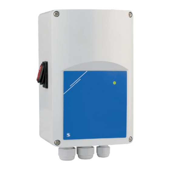
- Page 1 Speed controller rS-...-tA User’s manual...
-
Page 2: Table Of Contents
CONTENTS Purpose ..................................................2 Delivery set ................................................2 Technical data ............................................... 3 Design and operating principle ........................................ 8 Mounting and set-up ............................................8 Troubleshooting ..............................................18 Storage and transportation regulations ....................................19 PURPOSE The device is intended for use in ventilation systems for switching on/off and controlling rotation speed of single-phase electric motors in power-controlled fans. -
Page 3: Technical Data
TECHNICAL DATA Main technical parameters rS-3/0-tA rS-6/0-tA rS-10/0-tA Supply voltage [V/50 (60) Hz] ~220–240 Minimum current [A] Maximum current [A] F 5,0 A F 10,0 A F 16,0 A Fuse rating [A] H 250 VAC H 250 VAC H 250 VAC -20 ... - Page 4 operAtIon dIAGrAM normal / remote operation modes Acceleration mode deceleration mode Uout, [%] Uout, [%] Umax Umax range Umax range Umax Umax Umax Umin Umin range range 10 VDC 10 VDC 20 mA [VDC] / 20 mA [VDC] / [mA] [mA] Calculation Calculation...
- Page 5 normal / remote operation modes Acceleration mode deceleration mode Uout, [%] Uout, [%] Umax Umax Umax Umax range range Umin Umin Umin Umin range range t, [s] Duration of fast start Duration of fast start t, [s] Uout, [%] Uout, [%] Umax Umax Umax...
- Page 6 normal / remote operation modes Acceleration mode deceleration mode U max Umax U max range range U max Shutdown level Shutdown level Umin U min U min U min range range 10 VDC / t [s] 20 mA t [s] Duration of smooth start Duration of smooth start Uout, [%]...
- Page 7 timer mode logic mode Remote Uout, [%] switch 5 VDC Umax Voltage Umax range amplitude range 2,5 VDC U min range Umin t, [s] Ai,10 VDC / 20 mA Duration of fast start t [s] Standby mode Operation Smooth start is enabled Ai >2,4 VDC Soft start Soft start...
-
Page 8: Design And Operating Principle
DESIGN AND OPERATING PRINCIPLE Controller casing is made of non-flammable thermoplastic. The controller is equipped with an on/off button with backlight and an operation status indicator. Output power change from 30 to 100% is made proportionally to the control signal 0...10 V or 4-20 mA in the selected range during configuring the controller. - Page 9 InStAllAtIon InStrUctIonS Find a flat surface for mounting (wall, panel, etc.). Follow these steps: 1. Turn off the power. 2. Remove the front cover by removing the self-tapping screws and secure the controller to the wall or panel using screws through holes located in the back wall of the device.
- Page 10 3. Connect the motor / fan. The connection is made using screw terminals on the controller circuit board. 4. Connect L1 output for three-wire connection, adjustable valve, etc. (if necessary). See Fig. 3. Figure 3. electrical circuit diagram Analog output 0-10 VDC / 0-20 mA Power supply Modbus...
- Page 11 5. Select the desired analog input type and mode, start mode and shutdown level using the DIP switch on the circuit board. (See Fig. 4.). Figure 4. Setting the dIp switch ON — deceleration mode: Acceleration/deceleration 10–0 VDC / 20–0 mA mode selection OFF —...
- Page 12 6. A network bus terminator (NBT) is used to set the device as a terminator, and by default the NBT is disabled. It is installed manually on the pins that need to be connected (see Fig. 5). To ensure correct communication, the NBT jumper must be activated only in two devices in the Modbus RTU network (see example 1 and example 2).
- Page 13 7. Connect the power supply. 8. Adjust the max. speed using the trimmer (if necessary). The default setting is Us (230 VAC), see Fig. 6. 9. Adjust the min. speed using the trimmer (if necessary). Default is 30 % Us (69 VAC), see Fig. 7. 10.
- Page 14 Follow the instructions below: 1. Turn on the power. 2. Set the NBT jumper, DIP switch, max. speed trimmer, trimmer for min. speed and the off level trimmer to the desired positions / values. Factory settings are as follows: • the jumper is open (the mains bus resistor jumper is disconnected); •...
- Page 15 11. Check whether both LEDs (Fig. 9) are lit after turning on the device. If lit, your device has detected a Modbus network. If not, check the connection. Fig. 9. communication detection indication AttentIon! The status of LEDs can only be checked when power is supplied to the device. Follow all necessary safety precautions!
- Page 16 operAtInG MAnUAl operation modes In Modbus mode you control the following parameters: Umax, Umin, fast start / smooth start, acceleration / deceleration and shutdown level values with Modbus registers. In autonomous mode you control the following parameters: Umax, Umin, fast start / smooth start, acceleration / deceleration and shutdown level values with hardware settings (DIP switch, trimmers, jumpers).
- Page 17 led indication on the front panel When the green LED on the front panel (Fig. 10) is continuously lit, the controller is working in normal mode. If it flashes: • the controller works in remote control mode, or • the controller is turned off and the analog input signal is below the shutdown level. Fig.
-
Page 18: Troubleshooting
TROUBLESHOOTING trouble possible reasons troubleshooting Check the correct connection to the Limited or no connection. electrical power mains. Device is not working. The fuse has failed. Replace the fuse. Fan is not rotating when the Minimum fan rotation speed is set Adjust the minimum fan rotation speed. -
Page 19: Storage And Transportation Regulations
STORAGE AND TRANSPORTATION REGULATIONS • Store the unit in the manufacturer’s original packaging box in a dry closed ventilated premise with temperature range from +5 °C to + 40 °C and relative humidity up to 70 %. • Storage environment must not contain aggressive vapors and chemical mixtures provoking corrosion, insulation, and sealing deformation. - Page 20 Certificate of acceptance RS ____________________ TA The unit is recognized as serviceable. V47-7EN-02...
Need help?
Do you have a question about the RS TA Series and is the answer not in the manual?
Questions and answers