Table of Contents
Advertisement
Quick Links
Advertisement
Table of Contents

Related Manuals for SKY Engines 17F837


Summary of Contents for SKY Engines 17F837
- Page 1 SKY 150cc INSTRUCTION MANUAL...
- Page 2 INDEX 1.0 INTRODUCTION • 1.1 General warnings • 1.2 Recommendations for the prevention of accidents 2.0 DIRECTION FOR USE • 2.1 Fuel • 2.2 Running - in • 2.3 Starting the engine 3.0 TECHNICAL SPECIFICATIONS • 3.1 Engine illustration • 3.2 Technical specifications •...
-
Page 3: General Warnings
Sky Engines s.r.l. 1.1 GENERAL WARNINGS • SKY ENGINES shall not be directly or indirectly liable for the use of the engine, especially if it is altered or tampered with by third parties. • MAINTENANCE IS ESSENTIAL to avoid severely damaging the engine. Therefore, we advise you to CAREFULLY read Chapter 4.0 of this manual and thoroughly follow all the... -
Page 4: Recommendations For The Prevention Of Accidents
• SKY ENGINES reserves the right to change models and/or catalogues without warning and without any whatsoever obligation. Further information is provided on Web site www.skyengines.com • Aircraft driven by this engine must be used in open spaces only and in areas reserved for these activities. - Page 5 2.0 INSTRUCTIONS FOR USE The instructions for use in this manual refer to the production model at time of print; each type of change will not be directly notified to the buyer, but anyone looking for explanations on product development can check out the information you want on the website www.skyengines.com 2.1 FUEL...
-
Page 6: Starting The Engine
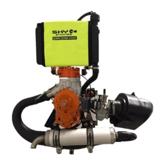
2.2 RUNNING - IN A good breaking-in ensures a long life of the engine and enhances the performance of its components. Use the engine very carefully during the first 3 hours of flight. Do not use the engine at maximum power for extended intervals of time. Do not keep the accelerator in the same position for several seconds;... - Page 7 3.1 FIGURE OF THE ENGINE 1: CYLINDER SK006 11: MUFFLER SK033 2: RADIATOR CAP SK013 12: IGNITION COIL SK040 13: RADIATOR’S HOSES 3: RADIATOR SK010 SK011/012 4: LAMINAR BUNDLE SK021/24/26 14: DRAIN RESERVOIR SK014 5: MUFFLER SEAL SK043 15: RADIATOR RODS SK017 6: HEAD + COVER SK007/08...
-
Page 8: Technical Specification
3.2 TECHNICAL SPECIFICATION SINGLE-CYLINDER 2 STAGE ENGINE WITH LIQUID TYPE COOLING SWEPT VOLUME: 150 CC MAX POWER 28 HP @ 10500 RPM MAX. RATED 10500 RPM SPEED: BORE 58 mm STROKE 55 mm REDUCTION MECHANICAL 1:4 OIL LUBRICATED 78/80 Kg WITH THREE CARBON BLADES 130 cm AT 10800 THRUST: (TESTS CARRIED OUT ON THE BENCH, WITHOUT FRAME WITH A TEMPERATURE OF 22 °... - Page 9 UNAUTHORIZED CHANGES THAT COULD DAMAGE THE ENGINES NOT COVERED BY WARRANTY. • Unauthorized changes could make the engine highly unstable! • Replace the components of the engine with original SKY ENGINES spare parts to guarantee a reliable operation. 3.3.2 RADIATOR(see also 3.3.3 RODS SILENT-BLOCK)
- Page 10 Then mount the tank as shown. Place the radiator on the cover and put the tubes in their respective outlets as shown below. Check the fitting positions and insert the clamp straps as in the photos. 3.3.3 SILENT BLOCK STAFF. Fit the teflon plate and then the silent blocks on the cover as shown in the figure.
- Page 11 Mount the brackets on the silent block of the cover and the silent blocks on the brackets. Place the tank on the bracket and screw the nut without tightening it, just to see the tip of the screw that goes out as in the figures to the side. Finally mount the radiator on the silent blocks.
- Page 12 3.3.4 CLUTCH Before mounting the clutch make sure you have the following pieces. Place the spring in the seat of the pile and place the clutch body as shown in the figure. Do this also on the other side. Place the whole in a vice by helping to fix it from a cylindrical body by matching the holes of the clamp and clutch body and pushing the pin as shown in the following figure.
- Page 13 Place the pins on both sides, also place the washers and nuts put a loctite handle to block the threads. Tighten the nut without tightening the clutch body completely, leaving the relatively free mops in the picture.
- Page 14 3.3.5 OVERALL IGNITION UNIT Take the flywheel and ensure everything needed is present, i.e. ratchets, screws and springs. Ensure the parts in question are clean. Position the spring in the specific hole and in the flywheel guide as in the photo to the side.
- Page 15 Position the threadlocker and the specific screw provided, tighten and ensure the ratchet remains free to rotate as in the 2 following photos. Grease the spring carefully. Couple the serrated pin with the spring, fitting the latter in the specific slot.
- Page 16 Position the spring-serrated pin unit in the specific compartment of the pulley, also here fitting the spring in the specific slot of the pulley. Then, screw in the grid as shown in the figures below. Insert the small spring from the other side of the pulley. As before, fit the spring well in the specific compartment.
- Page 17 Insert the cord in the hole of the pawl; tighten the grub screw on the cord, then insert it in the hole of the pulley. Lastly, fit the pawl in the specific hole on the pulley and wind the cord 8 rotations in the pulley as shown in the figures.
- Page 18 Position the rope in the specific hole of the cup. Insert the ignition unit assembled in the cup and connect the end of the small spring to the cup. Insert the bushing as in the figure and tighten it to the serrated pin.
- Page 19 Lastly, check everything is assembled correctly by pulling.
- Page 20 3.3.3 MUFFLER Mount the 3 washers bend over the bands and sort them as in the figure. Complete the muffler as shown in the figure Apply copper grease to the inner rim of the muffler manifold, then place the muffler on the manifold at the glue, pushing the manifold on the manifold as in the following figures.
- Page 21 Tighten with 2 screws M6 x 12 and washers the muffler fittings with silent blocks of the engine chassis; place 2 straps between the silent blocks and the muffler as in the side photo. Finally, insert the steel cable between the hooks by sliding it into the springs and tie it to the manifold side as in the picture below.
- Page 22 3.3.7 SILENCER Unscrew the bolts that connect the manifold to the base of the silencer. Unhook the tube base and remove the tube by holding the silencer out of the socket; then remove the worn glass wool. Hook the new glass wool, roll it up, recirculate the tube and screw down the manifold as shown in the following pictures.
- Page 24 3.3.8 LAMELLAR PACK Apply and distribute uniformly, avoiding sloping along the inner tube, an excessive amount of motors on the inner flange. Position the "paper" gasket and distribute another motorcycle layer equal to the previous one as in the following figures.
- Page 25 Place the lamellar unit inside the compartment in the crankcase, making sure that the "yellow" sheet is oriented upwards, for example toward the head (the difference in color can be seen from the 2 photos at the top left). Place another r layer of motorsil on the outside of the glue box, another paper gasket, and still motorsil, finally installing the carburetor and tightening as shown in the following figures.
- Page 26 3.3.9 CARBURETTOR Unscrew the screws and proceed to replace the accelerator cable. Open the cap by removing the spring and the guillotine. Hold the spring as in the figure, releasing the cable from its compartment in the guillotine.
- Page 27 Proceed to replace the cable, ensuring you have correctly fitted the end of the cable in the compartment of the guillotine as displayed in the figure below. 3.3.10 REDUCTION Unscrew the 4 screws to extract the reduction body. Proceed to check wear on the shoes. Unscrew the cap of the reduction unit and proceed to change the oil after 30 hours of use.
- Page 28 Add 30÷35 ml of oil. SKY Engines s.r.l. recommends using MOTUL GEAR 300. Alternatively, use thick synthetic oil.
-
Page 29: Maintenance
MAINTENANCE REMEMBER THE IMPORTANCE OF THIS CHAPTER OF THE MANUAL, READ ALL THE INSTRUCTIONS AND DEADLINES CAREFULLY; FOLLOW ALL THE ADVICE INDICATED FOR A LONGER LASTING ENGINE AND PREVENT PROBLEMS DUE TO WEAR. REMEMBER THAT DAMAGE DUE TO POOR MAINTENANCE WILL NOT BE COVERED BY WARRANTY. - Page 30 ATTENTION!! THE REFRIGERANT LIQUID SHOULD ALWAYS BE SUPPLIED WITH THE ENGINE COLD !!! IF LACKING, POUR THE LIQUID IN THE RADIATOR NOT THE TRAY, SINCE THE LATTER HAS THE SOLE FUNCTION OF COLLECTING THE EXCESS LIQUID IN THE RADIATOR AND NOT FILLING IT. THE EXCESS LIQUID IN THE TANK MAY FLOW OUT AND IF LEAKS ARE NOTED, FIRSTLY CHECK THIS;...
- Page 31 THE OIL LEVEL FOR REDUCTION SHOULD PERIODICALLY BE CHECKED USING THE BUSHING ON THE FRONT (with the engine in the vertical position, the correct level is under the lower line of the bushing, it must be completely visible). AFTER APPROX. 30 HOURS OR HAVING NOTED A CONSIDERABLE REDUCTION, REPLACE THE OIL INSIDE To do so, open the bushing, carefully drain all the exhausted oil and insert 30÷35 ml of synthetic oil for transmissions.
- Page 32 4.3 ADJUSTMENTS The only adjustment which could be necessary is air-petrol passage in the carburettor. For correct adjustment, carry out the operations outlined below: ATTENTION!!! ADJUST CARBURATION WITHOUT THE PROPELLER PRESENT! A – MECHANICAL ADJUSTMENT OF AIR PASSAGE B – MECHANICAL ADJUSTMENT OF THE MINIMUM PETROL PASAGE FOR CORRECT CARBURATION, TURN SCREW “B”...
- Page 33 4.4 SCHEDULES AND GENERAL RECOMMENDATIONS This paragraph lists a few recommendations that have been defined as a result of the tests carried out by our mechanics and on the basis of the feedback provided by customers. We kindly ask you to report anomalies or maintenance procedures that are not described in this manual using the space provided in chapter 7.0.
-
Page 34: Maintenance Schedule
MAINTENANCE SCHEDULE Deadline Check Change First 5 hours Global check tightening bolts And after 15 hours and screws Muffler’s silent blocks Every 25 hours conditions. Fixing wrappers • Clutch pads wear • Reduction oil level • Spark plug • Coolant level •... -
Page 35: Spare Parts
5.0 SPARE PARTS The manufacturer always recommends the use of original SKY ENGINES parts only. The catalog of spare parts is available on Web site: www.skyengines.com Spare parts can be ordered by contacting us directly by phone or e-mail, or through local distributors. -
Page 36: Warranty
- Damages (seizure) caused by the use of gasoline without added lubricant - Damages caused by the use of parts not specifically designed by Sky Engines - Damages caused by the use of the engine at speeds above those recommended by Sky Engines S.r.l. -
Page 37: Warranty Certificate
6.1 WARRANTY CERTIFICATE ENGINE CODE: ………………………………………………………………………. MODEL AND COLOR: ……………………………………………………………….. DISTRIBUTOR NAME: ……………………………………………………………….. DATE OF PURCHASE: ………………………………………………………………. SITE OF PURCHASE: ………………………………………………………………… THIS CERTIFICATE GUARANTEES THE ENGINE FOR ONE YEAR, STARTING FROM THE DATE OF PURCHASE. FOR DETAILED INFORMATION ON THE TERMS, CAREFULLY READ THE MANUAL. FOR FURTHER INFORMATION, PLEASE CONTACT US DIRECTLY BY PHONE OR E- MAIL OR VISIT www.skyengines.com... - Page 38 6.1 WARRANTY CERTIFICATE ENGINE CODE: ………………………………………………………………………. MODEL AND COLOR: ……………………………………………………………….. DISTRIBUTOR NAME: ……………………………………………………………….. DATE OF PURCHASE: ………………………………………………………………. SITE OF PURCHASE: ………………………………………………………………… THIS CERTIFICATE GUARANTEES THE ENGINE FOR ONE YEAR, STARTING FROM THE DATE OF PURCHASE. FOR DETAILED INFORMATION ON THE TERMS, CAREFULLY READ THE MANUAL. FOR FURTHER INFORMATION, PLEASE CONTACT US DIRECTLY BY PHONE OR E- MAIL OR VISIT www.skyengines.com...
- Page 39 6.1 WARRANTY CERTIFICATE ENGINE CODE: ………………………………………………………………………. MODEL AND COLOR: ……………………………………………………………….. DISTRIBUTOR NAME: ……………………………………………………………….. DATE OF PURCHASE: ………………………………………………………………. SITE OF PURCHASE: ………………………………………………………………… THIS CERTIFICATE GUARANTEES THE ENGINE FOR ONE YEAR, STARTING FROM THE DATE OF PURCHASE. FOR DETAILED INFORMATION ON THE TERMS, CAREFULLY READ THE MANUAL. FOR FURTHER INFORMATION, PLEASE CONTACT US DIRECTLY BY PHONE OR E- MAIL OR VISIT www.skyengines.com...
Need help?
Do you have a question about the 17F837 and is the answer not in the manual?
Questions and answers