Advertisement
INSTRUCTION MANUAL
DISCRETE INPUT, 8 points & NPN TRANSISTOR OUTPUT, 7 points MODULE
(High-speed Link System, independent I/O common)
BEFORE USE ....
Thank you for choosing M-System. Before use, please check
contents of the package you received as outlined below.
If you have any problems or questions with the product,
please contact M-System's Sales Office or representatives.
■ PACKAGE INCLUDES:
Discrete I/O module ............................................................(1)
■ MODEL NO.
Confirm Model No. marking on the product to be exactly
what you ordered.
■ INSTRUCTION MANUAL
This manual describes necessary points of caution when
you use this product, including installation, connection and
basic maintenance procedures.
SEN TRONIC
POINTS OF CAUTION
■ CONFORMITY WITH EU DIRECTIVE
• Use dual-shield cables (Shinko Seisen Industry Model
ZHY262 PBA) for the network. If it is not sufficient, use
a ferrite core (Kitagawa Industries Model GRFC-13) for
the network cable.
• The equipment must be mounted inside the instrument
panel of a metal enclosure.
• The actual installation environments such as panel con-
figurations, connected devices, connected wires, may af-
fect the protection level of this unit when it is integrated
in a panel system. The user may have to review the CE
requirements in regard to the whole system and employ
additional protective measures to ensure the CE conform-
ity.
■ POWER INPUT RATING & OPERATIONAL RANGE
• Locate the power input rating marked on the product and
confirm its operational range as indicated below:
24V DC rating: 24V ±10%, approx. 40mA
■ GENERAL PRECAUTIONS
• Before you remove the unit or mount it, turn off the power
supply, input signal and output signal for safety.
• DO NOT set the switches on the module while the power
is supplied. The switches are used only for maintenance
without the power.
■ ENVIRONMENT
• Indoor use.
• When heavy dust or metal particles are present in the
air, install the unit inside proper housing with sufficient
ventilation.
• Do not install the unit where it is subjected to continuous
vibration. Do not subject the unit to physical impact.
• Environmental temperature must be within -10 to +55°C
(14 to 131°F) with relative humidity within 30 to 90% RH
in order to ensure adequate life span and operation.
■ WIRING
• Do not install cables close to noise sources (relay drive
cable, high frequency line, etc.).
• Do not bind these cables together with those in which
noises are present. Do not install them in the same duct.
■ AND ....
• The unit is designed to function as soon as power is sup-
plied, however, a warm up for 10 minutes is required for
satisfying complete performance described in the data
sheet.
056 222 38 18
mailbox@sentronic.com
AG
R7HL-DAC15E
MODEL
EM-7812-AY Rev.1 P. 1 / 5
www.sentronic.com
Advertisement
Table of Contents

Related Manuals for M-system R7HL-DAC15E


Summary of Contents for M-system R7HL-DAC15E
- Page 1 (High-speed Link System, independent I/O common) BEFORE USE ..POINTS OF CAUTION Thank you for choosing M-System. Before use, please check ■ CONFORMITY WITH EU DIRECTIVE contents of the package you received as outlined below. • Use dual-shield cables (Shinko Seisen Industry Model If you have any problems or questions with the product, ZHY262 PBA) for the network.
-
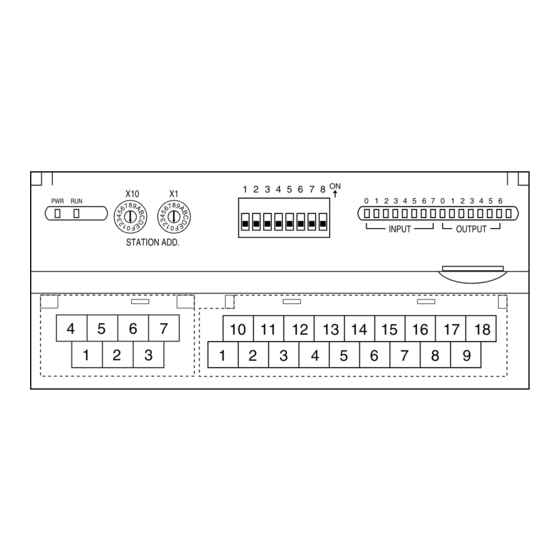
Page 2: Component Identification
R7HL-DAC15E COMPONENT IDENTIFICATION SIDE VIEW FRONT VIEW Operating Mode Setting DIP SW (SW1) Station Address Setting Rotary SW Discrete I/O Status Indicator LED Status Indicator LED INPUT OUTPUT STATION ADD. 10 11 12 13 15 16 17 18 Network, Power Supply... -
Page 3: Terminal Connections
R7HL-DAC15E ■ I/O TERMINAL ASSIGNMENT +24V FUNCTION FUNCTION Common Input 0 Input 1 Input 2 Input 3 Input 4 Input 5 Input 6 Input 7 +24V 24V DC 0V (Output common) Output 0 Output 1 Output 2 Output 3 Output 4... -
Page 4: Wiring Instructions
R7HL-DAC15E ■ CONNECTION DIAGRAM WIRING INSTRUCTIONS I/O Connection Example ■ SCREW TERMINAL (TR+) RXD+ PNP Input Torque: 0.5 N·m (TR –) RXD− − ■ SOLDERLESS TERMINAL (NC) TXD+ Refer to the drawing below for recommended ring tongue (NC) TXD− terminal size. Spade tongue type is also applicable. -
Page 5: Communication Cable Connections
R7HL-DAC15E COMMUNICATION CABLE CONNECTIONS MASTER CONNECTION • Full-duplex communication Master Module Slave Module Slave Module TXD + RXD + RXD + TXD – RXD – RXD – Terminating Terminating RXD + TXD + TXD + Resistor Resistor RXD – TXD –...
Need help?
Do you have a question about the R7HL-DAC15E and is the answer not in the manual?
Questions and answers