
Related Manuals for a-TroniX AX Series


Summary of Contents for a-TroniX AX Series
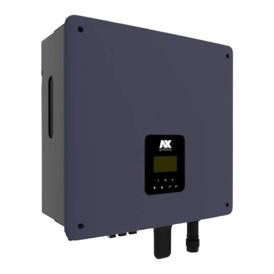
- Page 1 Machine Translated by Google INVERTER Installation and operating instructions AX series, 1ph atx009de-en0823...
-
Page 2: Table Of Contents
Machine Translated by Google Operating instructions a-TroniX inverter AX series, 1ph INTRODUCTION The publication and copyright of this documentation remain with the company: AKKU SYS Accumulator and Battery Technology Nord GmbH Connection path 23 D-25469 Halstenbek · GERMANY Telephone +49 4101 37676-0 · Fax +49 4101 85475-66 info@akkusys.de ·... - Page 3 Machine Translated by Google Operating instructions a-TroniX inverter AX series, 1ph 4. Technical data 4.1 PV input (only for hybrid) 4.2 Battery 4.3 AC Output/Input 4.4 EPS Output 4.5 Efficiency and Protection 4.6 General data 5. Installation 5.1 Check for physical damage 5.2 Packing list 5.3 Assembly...
-
Page 4: Notes About This Manual
1.Notes about this manual 1.1 Scope This manual describes the assembly, installation, commissioning, maintenance and troubleshooting for the following models of the a-TroniX products: AX3.0kW-1ph, AX3.7kW-1ph, AX4.6kW-1ph, AX5.0kW-1ph, AX6.0kW-1ph A NOTICE Please keep these instructions so that they are accessible at all times. -
Page 5: Intended Use 2.2 Pe Connection And
2. Security 2.1 Intended use The inverters of the a-TroniX series AX were developed and tested in accordance with international safety requirements. However, certain safety precautions must be taken when installing and operating this inverter. The installer must read and follow all instructions, safety notices and warnings in this installation manual. -
Page 6: Leakage Current
Machine Translated by Google • Do not install the device in unfavorable environmental conditions, such as e.g. B. in the immediate vicinity of flammable or explosive substances, in a corrosive or desert-like environment, at extremely high or low temperatures or in high humidity. •... - Page 7 Machine Translated by Google Residual current device (RCD) • All a-TroniX inverters are equipped with a certified internal residual current protective device (RCD) that protects against a possible malfunction in the event of a malfunction of the PV generator, cables or inverter (DC).
-
Page 8: Surge Protection Devices (Spds) For Pv Installation
Machine Translated by Google 2.3 Surge protection devices (SPDs) for PV installation WARNING! When installing the PV system, surge protection with surge arresters should be provided. The grid-connected inverter is not equipped with SPDs on either the PV input side or the grid side. -
Page 9: Introduction
3. Introduction 3.1 Basic properties The high-quality inverters of the AX series are used to convert solar energy into alternating current and store energy in the battery. The inverter can be used to optimize self-consumption, to store in the battery for later use or to feed into the public grid. -
Page 10: Dimensions
Machine Translated by Google Working mode Working mode description Priority: Load > Battery > Own consumption Grid The energy generated by the PV system is used to (with optimize self-consumption. The excess energy is used to PV power) charge the batteries and then exported to the grid. Own consumption If there is no PV feed-in, the battery first discharges for local loads. -
Page 11: Inverter Terminals
Machine Translated by Google 3.3 Inverter terminals Article Description DC switch (only for hybrid) PV1 (Only for Hybrid) PV2 (Only for Hybrid) Battery connections Measuring device / CT / RS485 WiFi/4G/USB PARALLEL 1 PARALLEL 2 GRID Waterproof lock valve Grounding screw A NOTICE: Only authorized personnel are allowed to establish the connection. -
Page 12: Technical Data
Machine Translated by Google Operating instructions a-TroniX inverter AX series, 1ph 4. Technical data 4.1 PV input (only for hybrid) 3kW 3.7kW 4.6kW 5kW 6kW Model AX, 1ph 4500 5500 6900 7500 9000 A:4500 A:2250 A:2750 A:3450 A:3750 Max. recommended DC power [W]... -
Page 13: Ac Output/Input 4.4 Eps
Machine Translated by Google 4.3 AC output/input 3.7kW 4.6kW 5kW Model AX, 1ph AC OUTPUT 3000 3680 4600 5000 6000 AC rated power [VA] 3300 4600 5500 4048 6600 Max. AC apparent power [VA] Nominal mains voltage 220 / 230 / 240 (180 to 270) (AC voltage range) [V] 50 / 60, ±5 Nominal mains frequency [Hz]... -
Page 14: Output 4.5 Efficiency
Machine Translated by Google 4.4 EPS output 3kW 3.7kW 4.6kW 5kW 6kW Model AX, 1ph EPS OUTPUT (WITH BATTERY) 6000 3000 3680 4600 5000 Max. EPS power [VA] 220/230/240VAC, 50/60 EPS nominal voltage [V], frequency [Hz] 3600 4400 5500 6000 7200 EPS peak power (60s) [W] 27.3... -
Page 15: General Data
Machine Translated by Google 4.6 General data 3kW 3.7kW 4.6kW 5kW 6kW Model AX, 1ph MEASURES AND WEIGHT 434*418*185 Dimensions (W x H x D) [mm] Net weight [kg] Naturally Cooling concept Art Not isolated Inverter topology WLAN / LAN / 4G /GPRS (optional), communication DRM, USB, CT LCD display... -
Page 16: Installation
Machine Translated by Google 5. Installation 5.1 Check for physical damage Make sure that the inverter was undamaged during transport. If there is visible damage, such as: B. Cracks, please contact your dealer immediately. 5.2 Packing list Open the package and take out the product, please check the accessories first. The packing list is shown below. Installation Guide Object quantity description Object quantity description... -
Page 17: Assembly
Machine Translated by Google 5.3 Assembly Installation precautions Make sure the installation location meets the following conditions: • Not in direct sunlight • Not in areas where highly flammable materials are stored • Not in potentially explosive areas • Not directly in cool air •... - Page 18 Machine Translated by Google Assembly steps Tools required for installation: • Hand screwdriver; • Electric drill (8mm drill set); • Crimping pliers; wire stripper; Screwdriver. Installation angle requirements: • Do not tilt the energy storage unit forward, horizontally, upside down, backwards or sideways. Installation space requirements: •...
- Page 19 Machine Translated by Google • Insert the dowels into the holes and tighten them. Assemble the bracket with the screws. 2. Adjusting the inverter to the wall mount • Hang the inverter over the mount, lower the inverter slightly and make sure that the 2 mounting rods on the back are properly secured in the 2 grooves of the mount.
-
Page 20: Electrical Connection
Machine Translated by Google 6. Electrical connection 6.1 PV connection (only for hybrid) Step 1: PV string connection The AX 1ph series inverters can be connected to 2 strings of PV modules. Please choose suitable PV modules with high reliability and quality. - Page 21 Machine Translated by Google Operating instructions a-TroniX inverter AX series, 1ph Step 2: PV Wiring • Turn off the DC switch. • Select 12 AWG wire for connecting the PV module. • Cut 6mm of insulation from the end of the wire.
-
Page 22: Connecting The Battery
Machine Translated by Google Operating instructions a-TroniX inverter AX series, 1ph 6.2 Connecting the battery • Turn off the DC switch. • Choose 8 AWG wire for connecting the battery. • Cut 6mm of insulation from the end of the wire. -
Page 23: Ac Connection
Machine Translated by Google Operating instructions a-TroniX inverter AX series, 1ph 6.3 AC connection Step 1: AC string connection The AX1ph series inverters are designed for single-phase networks. The voltage range is 220/230/240V; the frequency is 50/60Hz. Other technical requirements should comply with the requirements of the local public network. - Page 24 Machine Translated by Google Operating instructions a-TroniX inverter AX series, 1ph Step 2: Power Wiring • Check the mains voltage and compare it with the permissible voltage range (see technical data). • Switch off the circuit breaker from all phases and secure it against being switched on again.
- Page 25 Machine Translated by Google Operating instructions a-TroniX inverter AX series, 1ph • Insert the male end into the female end. For the direction of rotation of the lock, please note the LOCK marking on the assembly. • Press the threaded sleeve onto the Connecting terminal until both are firmly attached Inverters are engaged.
-
Page 26: Ground Connection
3. For WiFi device: Connect the WiFi device to the local router and complete the WiFi configuration (see the for more details WLAN product manual). 4. Set up the location account on the a-TroniX monitoring platform (please refer to the monitoring user manual for further details). Page 26... - Page 27 Machine Translated by Google Operating instructions a-TroniX inverter AX series, 1ph • Measuring device /CT/ RS485 The inverter has an integrated export limitation function. To use this feature, a power meter or current transformer must be installed. The meter/CT/485 PIN definitions Interface are as follows.
- Page 28 Machine Translated by Google Operating instructions a-TroniX inverter AX series, 1ph If there is another generator in the home, CT2 can be used to record the power produced by the generator and transmit the data to the website for monitoring.
- Page 29 Machine Translated by Google Operating instructions a-TroniX inverter AX series, 1ph Setting the export limit: ON-NET SETTINGS EXPORT CONTROL xxxxxW PARM The ammeter is connected as follows: A NOTICE Counter Type: DDSU666 (CHINT) Page 29 atx009de0823...
- Page 30 Machine Translated by Google Operating instructions a-TroniX inverter AX series, 1ph • BMS The communication interface between inverter and battery is RS485 or CAN with an Rj45 connector. pin code definition / GND BMS-485B BMS-CANL BMS-CANH / / BMS-485A Steps to connect:...
- Page 31 Machine Translated by Google Operating instructions a-TroniX inverter AX series, 1ph • DRM DRM0 setting: ACTIVATE / CHARACTERISTIC ATTITUDE DRM0 DEACTIVATE PARM The DRM supports multiple demand response modes by issuing control signals as described below. Mode Conditions DRM0 Operate the disconnect device.
- Page 32 Machine Translated by Google Operating instructions a-TroniX inverter AX series, 1ph • COM ESTOP: Close the inverter. Generator: Connect the generator and put it into operation. CAN: External debugging. pin code Definition +3.3V GND GENERATOR BMS-CANL BMS-CANH +3.3V GND ESTOP...
-
Page 33: Eps Connection
Machine Translated by Google Operating instructions a-TroniX inverter AX series, 1ph 6.6 EPS connection A. EPS wiring EPS mode can be achieved by two different types of wiring. On the one hand, the internal bypass can be used to connect the home emergency call loads to the EPS connection of the inverter. - Page 34 Machine Translated by Google Operating instructions a-TroniX inverter AX series, 1ph Using external EPS wiring: A NOTICE 1. EPS box (optional): Used for on-grid and EPS switching of inverters, improves the maximum EPS load capacity, the max. bypass current is 60A.
-
Page 35: System Connection Diagrams
Machine Translated by Google Operating instructions a-TroniX inverter AX series, 1ph 6.7 System connection diagrams The neutral conductor of the alternative power supply must be isolated or switched. For countries such as Australia, New Zealand, South Africa, etc., please follow local wiring regulations. -
Page 36: Commission The Inverter
Machine Translated by Google Operating instructions a-TroniX inverter AX series, 1ph 6.8 Put the inverter into operation Please note the following steps for commissioning the inverter. 1. Make sure the inverter is well secured. 2. Make sure all DC and AC wiring is completed. -
Page 37: Control Panel
Machine Translated by Google Operating instructions a-TroniX inverter AX series, 1ph 7. Surgery 7.1 Control panel Surname function object LCD screen displaying the inverter information. The inverter is in fault mode. Red: The inverter is normally connected to Indicator LED Blue: the battery. -
Page 38: Function Tree
Machine Translated by Google Operating instructions a-TroniX inverter AX series, 1ph 7.2 Function tree Page 38 atx009de0823... -
Page 39: Maintenance 8.1 Overview Of Error Codes
AX series, 1ph 8. Maintenance This section provides information and procedures for troubleshooting possible problems with the a-TroniX inverters and gives you troubleshooting tips to identify and solve most problems that may arise. 8.1 Alarm list Error code Solution The power grid is interrupted. - Page 40 Machine Translated by Google Operating instructions a-TroniX inverter AX series, 1ph Error code Solution The differential current is high. Res Cur • Check whether the insulation of the electrical wires is damaged. • Wait a Mistake while to check if the insulation returns to normal. • Or seek help from us.
- Page 41 Machine Translated by Google Operating instructions a-TroniX inverter AX series, 1ph Error code Solution Communication between master and slave has failed. MDSP SPI • Disconnect the PV, grid and battery and then reconnect them. Mistake • Or seek help from us if you cannot return to normal.
- Page 42 Machine Translated by Google Operating instructions a-TroniX inverter AX series, 1ph Error code Solution M1 Error closing M1 error • Disconnect the PV, grid and battery and then reconnect them. close • Or seek help from us if you cannot return to normal.
- Page 43 Machine Translated by Google Operating instructions a-TroniX inverter AX series, 1ph Error code Solution DIP switch in wrong position; Communication between the battery packs is interrupted. BMS Int • Put the DIP switch in the correct position; Mistake • Check whether the communication cable between the battery packs is connected correctly and well.
-
Page 44: Troubleshooting And Routine Maintenance
(5) Are the configuration settings correct for your particular installation? (6) Are the display panel and communication cable connected correctly and undamaged? Contact a-TronIX customer service for further assistance. Please be prepared to describe details of your system installation and provide the device model and serial number. -
Page 45: Decommissioning 9.1 Dismantling The
Machine Translated by Google • Check whether the inverter displays are in normal state, check whether the inverter display is normal. These checks should be carried out at least every 6 months. • Check whether the input and output cables are damaged or aged. This check should be carried out at least every 6 months. - Page 46 Machine Translated by Google www.a-tronix.de AKKU SYS Accumulator and Battery Technology Nord GmbH Connection path 23 · 25469 Halstenbek · GERMANY Phone +49 4101 37676-0 · info@akkusys.de www.akkusys.de · akkusys.shop · www.a-tronix.de...
-
Page 47: Inverter
Machine Translated by Google INVERTERS User Manual AX series, 1ph atx009en0823 Page 47... - Page 48 AKKU SYS GmbH accepts no liability for errors in this operating manual and any consequences resulting therefrom. Our EU declaration of conformity and warranty conditions can be found on: www.a-tronix.de Table of Contents page 1. Notes on This Manual 1.1 Scope of Validity 1.2...
- Page 49 Machine Translated by Google 4. Technical data 4.1 PV Input (For 3ph Only) 4.2 Battery 4.3 AC Output/Input 4.4 EPS Output 4.5 Efficiency and Protection 4.6 General Data 5. Installation 5.1 Check for Physical Damage 5.2 Packing List 5.3 Mounting 6. Electrical Connection 6.1 PV Connection (For 3ph Only) 6.2 Battery Connection 6.3...
-
Page 50: Notes On This Manual
Machine Translated by Google 1. Notes on This Manual 1.1 Scope of Validity This manual describes the assembly, installation, commissioning, maintenance and troubleshooting of the following model(s) of products: AX3.0kW-1ph, AX3.7kW-1ph, AX4.6kW-1ph, AX5.0kW-1ph, AX6.0kW-1ph GRADE Please keep this manual where it will be accessible at all times. 1.2 Target Group This manual is for qualified electricians. -
Page 51: Appropriate Usage 2.2 Pe
PE conductor terminal 2. Safety 2.1 Appropriate Usage a-TroniX AX series inverters are designed and tested in accordance with international safety requirements. However, certain safety precautions must be taken when installing and operating this inverter. The installer must read and follow all instructions, cautions and warnings in this installation manual. -
Page 52: Connection And Leakage Current 2.3 Surge
Machine Translated by Google • Do not use the equipment when the safety devices do not work or are disabled. • Use personal protective equipment, including gloves and eye protection during the installation. • Inform the manufacturer about non-standard installation conditions. •... - Page 53 Machine Translated by Google Residual Current Device (RCD) • All inverters incorporate a certified internal RCD (Residual Current Device) to protect against possible electrocution in case of a malfunction of the PV array, cables or inverter (DC). The RCD in the inverter can detect leakage on the DC side.
-
Page 54: Protection Devices (Spds) For Pv Installation 3. Introduction
Machine Translated by Google 2.3 Surge Protection Devices (SPDs) for PV installation WARNING Over-voltage protection with surge arresters should be provided when the PV power system is installed. The grid connected inverter is not fitted with SPDs in both PV input side and mains side. -
Page 55: Basic Features
3.Introduction 3.1 Basic Features AX series are high-quality inverters which can convert solar energy to AC energy and store energy into battery. The inverter can be used to optimize self-consumption, store in the battery for future use or feed-in to public grid. -
Page 56: Dimensions
Machine Translated by Google User Manual a-TroniX Inverter AX-series, 1ph Work modes Work modes Description Priority: load>battery>grid Self-use The energy produced by the PV system is used to optimize (with PV power) self-consumption. The excess energy is used to charge the batteries, then exported to gird. -
Page 57: Terminals Of Inverters
Machine Translated by Google 3.3 Terminals of Inverters item Description DC Switch (For Hybrid Only) PV1 (For Hybrid Only) PV2 (For Hybrid Only) Battery connector Meter/CT/RS485 WiFi/4G/USB PARALLEL 1 PARALLEL 2 GRID Waterproof lock valve Grounding screw GRADE Only authorized personnel are permitted to set the connection. atx009en0823 Page 57... -
Page 58: Technical Data
Machine Translated by Google 4. Technical data 4.1 PV Input (For Hybrid Only) 3kW 3.7kW 4.6kW 5kW 6kW Model AX, 1ph 4500 5500 6900 7500 9000 A:2250 A:2750 A:3450 A:3750 A:4500 Max. recommended DC power [W] B:2250 B:2750 B:3450 B:3750 B:4500 Max. -
Page 59: Ac Output/Input 4.4 Eps
Machine Translated by Google 4.3 AC Output/Input 3kW 3.7kW 4.6kW 5kW Model AX, 1ph AC OUTPUT 3000 3680 4600 5000 6000 Nominal AC power [VA] 6600 3300 4048 4600 5500 Max. apparent AC power [VA] Rated grid voltage (AC voltage range) [V] 220 / 230 / 240 (180 to 270) 50 / 60, ±5 Rated grid frequency [Hz]... -
Page 60: Output 4.5 Efficiency
Machine Translated by Google 4.4 EPS output 3kW 3.7kW 4.6kW 5kW 6kW Model AX, 1ph EPS Output (WITH BATTERY) 3000 3680 4600 5000 6000 Max. EPS power [VA] 220/230/240VAC, 50/60 EPS rated voltage[V], Frequency [Hz] 3600 4400 5500 6000 7200 EPS peak power (60s) [W] 27.3 20.9... - Page 61 Machine Translated by Google 4.6 General Data 3kW 3.7kW 4.6kW 5kW 6kW Model AX, 1ph DIMENSION AND WEIGHT 434*418*185 Dimension (W*H*D) [mm] Weight [kg] Natural Cooling concept Non-Isolated Inverter topology WiFi / LAN / 4G /GPRS (optional), Communication DRM, USB, CT LCD display LCD, app, website ENVIRONMENT LIMIT...
-
Page 62: Installation
Machine Translated by Google 5. Installation 5.1 Check for Physical Damage Make sure the inverter is intact during transportation. If there is any visible damage, such as cracks, please contact your dealer immediately. 5.2 Packing List Open the package and take out the product, please check the accessories first. The packing list shown below. -
Page 63: Mounting
Machine Translated by Google 5.3 Mounting Installation Precaution Make sure the installation site meets the following conditions: • Not in direct sunlight. • Not in areas where highly flammable materials are stored. • Not in potentially explosive areas. • Not in the cool air directly. •... - Page 64 Machine Translated by Google Mounting Steps Tools required for installation: • Manual wrench; • Electric drill (drill bit set 8mm); • Crimping pliers; • Stripping pliers; • Screwdriver. Step 1: Fix the bracket on the wall • Choose the place you want to install the inverter. Place the bracket on the wall and mark the position of the 5 holes from bracket.
- Page 65 Machine Translated by Google Step 2: Match the inverter with wall bracket • Hang the inverter over the bracket, slightly lower the inverter, and make sure the 2 grooves on the back are fixed with the 2 mounting bars from bracket properly. Fixing inverter with the supplied M5 screw.
-
Page 66: Electrical Connection
Machine Translated by Google 6. Electrical Connection 6.1 PV Connection (For Hybrid Only) Step 1: PV String Connection AX 1ph series inverters can be connected with 2-strings of PV modules. Please select suitable PV modules with high reliability and quality. Open circuit voltage of module array connected should be less than 600V, and operating voltage should be within the MPPT voltage range. - Page 67 Machine Translated by Google Step 2: PV wiring • Turn off the DC switch. • Choose 12 AWG wire to connect the PV module. • Trim 6mm of insulation from the wire end. • Separate the DC connector (PV) as below. •...
-
Page 68: Battery Connection
Machine Translated by Google 6.2 Battery Connection • Turn off the DC switch. • Choose 8 AWG wire to connect the battery. • Trim 6mm of insulation from the wire end. • Separate the DC connector (battery) as below. • Insert striped cable into pin contact and ensure all conductor strands are captured in the pin contact. -
Page 69: Grid Connection
Machine Translated by Google 6.3 AC Connection Step 1: AC String Connection AX1ph series inverters are designed for single-phase grid. Voltage range is 220/230/240V; frequency is 50/60Hz. Other technical requests should comply with the requirement of the local public grid. Table1: Without EPS Function (internal) Model (kW) Cable (GRID) (mm²) - Page 70 Machine Translated by Google Step 2: AC Wiring • Check the grid voltage and compare with the permitted voltage range (refer to technical data). • Disconnect the circuit breaker from all the phases and secure against reconnection. • Trim the wires: - Trim all the wires to 52.5mm and the PE wire to 55mm.
- Page 71 Machine Translated by Google • Insert the male end into the female end. For the rotation direction of the lock, please refer to the LOCK mark on the assembly. • Push the threaded sleeve to connect terminal until both are locked tightly on the inverter.
-
Page 72: Earth Connection
Connect the WiFi with the local router, and complete the WiFi configuration (please refer to the WiFi product manual for more details). 4. Set-up the site account on the a-TroniX monitoring platform (please refer to the monitoring user manual for more details). - Page 73 Machine Translated by Google • Meters /CT/ RS485 The inverter has integrated export limitation functionality. To use this function, a power meter or a CT must be installed. The PIN definitions of Meter/CT/485 interface are as below. pin code meter meter Loggers Loggers...
- Page 74 Machine Translated by Google If there is another generator in the home, Meter2 or CT2 can be used to record the power generated by the generator and transmit the data to the website for monitoring. GRADE For a precise reading and control of power, a meter can be used instead of a CT.
- Page 75 Machine Translated by Google Export limitation setting: ON GRID SETTINGS EXPORT CONTROL xxxxxW PARM The electricity meter is connected as follows: GRADE Meter type: DDSU666 (CHINT) atx009en0823 Page 75...
- Page 76 Machine Translated by Google • BMS Communication interface between inverter and battery is RS485 or CAN with a Rj45 connector. pin code definition / GND BMS-485B BMS-CANL BMS-CANH / / BMS-485A Connection steps: Step1: Prepare a standard network cable and cable connector, then insert the network cable through the cable connector.
- Page 77 Machine Translated by Google • DRM DRM0 setting: FEATURE SETTINGS DRM0 ENABLE/DISABLE PARM DRM is provided to support several demand response modes by emitting control signals as below. Mode Requirement DRM0 Operate the disconnection device. DRM1 Do not consume power. DRM2 Do not consume at more than 50% of rated power.
- Page 78 Machine Translated by Google • COM ESTOP: Close the inverter. Generator: Connect the generator and start-up it. CAN: External debug. pin code Definition +3.3V GND GENERATOR BMS-CANL BMS-CANH +3.3V GND ESTOP Model Function Socket asserted by shorting pins ESTOP Emergency stop the inverter Connection steps: Step 1: Screw this plate off from inverter.
-
Page 79: Eps Connection (Non-Parallel State)
Machine Translated by Google 6.6 EPS Connection A.EPS Wiring EPS mode can be achieved by two different types of wiring methods. One is using the internal bypass to wire the house emergency loads on the EPS port from inverter. Another is using external contactor to wire the EPS loads on the contactor itself (External contactor need to be purchased separately). - Page 80 Machine Translated by Google Use External EPS Wiring: GRADE 1. EPS Box (Optional): Used for On-Grid and EPS switching of inverters, improve maximum EPS loads capacity, maximum bypass current is 60A. 2. When the grid power is off, ensure that the back-up load power is lower than the inverter's maximum output power.
-
Page 81: System Connection Diagrams
Machine Translated by Google 6.7 System Connection Diagrams Neutral line of alternative supply must be isolated or switched. For countries such as Australia, New Zealand, South Africa, etc., please follow local writing regulations! network Neutral line of alternative supply must be disconnected after the grid is off. For countries such as China, Germany, the Czech Republic, Italy, etc., please follow local writing regulations! network... -
Page 82: Inverter Start-Up
Machine Translated by Google 6.8 Inverter start-up Please refer to the following steps to start up the inverter. 1. Ensure the inverter fixed well. 2. Make sure all the DC wirings and AC wirings are completed. 3. Make sure the meter is connected well. 4. -
Page 83: Surgery
Machine Translated by Google 7. Surgery 7.1 Control Panel Function Surname Object LCD screen Display the information of the inverter. Red: The inverter is in fault mode. The inverter is normally Indicator LED Blue: connected to the battery. Green: The inverter is in normal state. Move cursor to upside or button: increase value. -
Page 84: Function Tree
Machine Translated by Google 7.2 Function Tree atx009en0823 Page 84... -
Page 85: Maintenance
Machine Translated by Google 8.Maintenance This section contains information and procedures for solving possible problems with the inverters and provides you with troubleshooting tips to identify and solve most problems that can occur. 8.1 Alarm List Solution Faulty code Grid is lost. Grid Lost •... - Page 86 Machine Translated by Google Faulty code Solution The isolation has failed. • Please check if the insulation of electrical wires is damaged. • Wait Iso Fault for a while to check if back to normal. • Or seek for help from us. The residual current is high.
- Page 87 Machine Translated by Google Faulty code Solution Battery current high detected by hardware. HW Bat Cur • Disconnect PV, grid and battery, then reconnect. Fault • Or seek help from us, if not go back to normal state. The communication between master and manager is fail. SCI Fault •...
- Page 88 Machine Translated by Google Faulty code Solution The battery connection is reversed. BatCon Dir • Check if the positive pole and negative pole of battery are correctly connected. Fault • Or seek help from us. The grid relay keeps open. Main relay •...
- Page 89 Machine Translated by Google Faulty code Solution The communication between BMS and inverter is interrupted. BMS Lost • Check if the communication cable between BMS and inverter is correct and well connected. The communication between BMS and inverter is interrupted. BMS Ext Fault •...
-
Page 90: Troubleshooting And Routine Maintenance
Machine Translated by Google 8.2 Troubleshooting and Routine Maintenance • Troubleshooting a. Please check the fault message on the System Control Panel or the fault code on the inverter information panel. If a message is displayed, record it before doing anything further. -
Page 91: Decommissioning
Machine Translated by Google • Check if the input and output wires are damaged or aged. This check should be performed at least every 6 months. • Get the inverter panels cleaned and their security checked at least every 6 months. - Page 92 Machine Translated by Google www.a-tronix.de atx009de-en0823 If you have any questions, please contact us! AKKU SYS Accumulator and Battery Technology Nord GmbH Connection path 23 · 25469 Halstenbek · GERMANY Telephone +49 4101 37676-0 · info@akkusys.de www.akkusys.de · akkusys.shop · www.a-tronix.de V1.0...
Need help?
Do you have a question about the AX Series and is the answer not in the manual?
Questions and answers