
Related Manuals for ARAG bravo 350 Series


Summary of Contents for ARAG bravo 350 Series
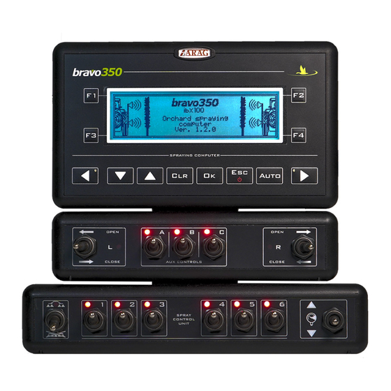
- Page 1 BRAVO 350 SERIES COMPUTER ORCHARD SPRAYER DIRECT CONNECTION 467354XXXX Software rel. 1.3.x INSTALLATION, USE AND MAINTENANCE...
-
Page 2: Legend Of Symbols
This manual is an integral part of the equipment to which it refers and must always accompany it even in case of sale or transfer. Store it for any future consultation; ARAG reserves the right to modify specifications and instructions of the product at any time and without prior notice. -
Page 3: Table Of Contents
CONTENTS • Legend of symbols ..............2 9.9 Tank ................31 • Manual foreword and use ............4 9.10 Speed................32 • Manual use modes ..............4 9.10.1 Source - Wheel sensor ............ 33 9.10.2 Source - GPS ..............33 • LIMITATIONS ................4 9.11 Flowrate correct. -
Page 4: Manual Foreword And Use
• RESPONSIBILITY The installer must carry out workmanlike installations and ensure to the end user the perfect operation of the whole system both with ARAG components only and other brands' components. ARAG always recommends using its components to install control systems. -
Page 5: Package Content
- Control unit with solenoid or motorized section valves - Bulkhead actuators (if provided) Seals for valve connectors Fixing kit Sensors, control units and accessories must be ordered separately (Ref. ARAG general catalog). Fig. 1 SYSTEM RECOMMENDED COMPOSITION OP EN DR IFT... -
Page 6: Monitor Position
INSTALLATION Monitor position BRAVO 350 must be placed in the control cabin of the farming machine. Observe the following precautions: - Do NOT install the monitor in areas where it would be subjected to excessive vibrations or shocks, to prevent any damage or accidental use of the control keys;... -
Page 7: Installation Of Ultrasonic Sensors
Computer correct operation is ensured only if ARAG-distributed sensors are used: use of unsuitable sensors not provided by ARAG automatically voids the warranty. ARAG is not liable for any damage to the equipment, persons or animals caused by failure to observe the above indications. - Page 8 INSTALLATION 6.4.1 Fixing of sensors on the machine After having located sensor position, based on the height of the plants you wish to spray, select the fixing point on the machine and fix sensors by following the instructions provided by the manufacturer. WARNING: sensors must be always fixed parallel with the ground and at a right angle to the plant to be sprayed (Fig.
-
Page 9: Wiring Connections
• Use of unsuitable cables not provided by ARAG automatically voids the warranty. • ARAG is not liable for any damage to the equipment, persons or animals caused by failure to observe the above instructions. Use ONLY the cables and accessories indicated in the catalog, having technical features suitable for the use to be made of them. -
Page 10: Connection To The Control Unit Valves And To The Solenoid Section Valves
INSTALLATION Connection to the control unit valves and to the solenoid section valves Fix the connectors to the relevant valves according to the indicated initials. • Remove the protective cap (1) from the valve. • Place the seal (2) onto the connector (3), and push the connector fully on (4): be careful not to bend the contacts upon insertion on the valve. -
Page 11: Connection Of Ultrasonic Sensors
INSTALLATION Connection of ultrasonic sensors Connect the ultrasonic sensor connectors: after having made sure that they are duly inserted, turn ring nut until it locks in place. WARNING: always check the correspondence between sensors (cable marking) and sections, in order to spray exactly in the point detected by the sensor. The table below shows the correspondences between sensors and sections. -
Page 12: Connection Of Sensors And Available Functions
INSTALLATION Connection of sensors and available functions ARAG sensors feature a Tyco Superseal ® connector. Insert the connector fully home until the locking tab clicks into place. The single products are supplied with the sensor connecting instructions. Fig. 20 Fig. 19... -
Page 13: Setting
SETTING SETTING Tests and checks before setting Before computer setting, check: • that all components are correctly installed (control unit and sensors); • the correct connection to the power source; • the component connection (main control unit and sensors). Failure to correctly connect system components or to use specified components might damage the device or its components. Computer switching on/off •... -
Page 14: Use Of Keys For Setting
SETTING Use of keys for setting Advanced Setup > Language : ... > Use cursor to select the menu you want to Unit of measurement : Metric access: move it using the "arrow" keys until Ultrasonic configuration : ... selecting the option you are looking for (Fig. 28). Valves configuration : ... -
Page 15: Advanced Setup
2271 pls/gal 00004 pls/gal 37850 pls/gal Pressure sensor Par. 8.6 Type Disabled ARAG 466113.200 - ARAG 466113.500 - Other... 000.1 bar 150.0 bar Maximum pressure Item active only if a sensor is selected 001 psi 2175 psi Delivery cal. sensor... -
Page 16: Ultrasonic Configuration
ADVANCED SETUP External device None Serial LOG - B400S / D80 - IBX20 Par. 8.9 Access level Technician Operator - Manager - Technician - ARAGTech Par. 8.10 Rev counter Not present in the bulkhead version Par. 8.11 Constant Disabled 00000 pls/rev 10000 pls/rev Minimum speed alarm 100 rpm... -
Page 17: Valves Configuration
ADVANCED SETUP Valves configuration Set the type of valves installed on the system and the relevant data. > Master : indicate the type of installed main control valve. 2 ways : drain valve 3 ways : main valve None > Pressure regulator : indicate the type of installed control valve. -
Page 18: Bulkheads
ADVANCED SETUP Bulkheads Bulkhead mode : indicate the type of bulkhead operation. Manual : The bulkhead status only depends on the position of the relevant switches (L/R - OPEN/ CLOSE). Boom status : The bulkhead status, when the switches are in the “CLOSE” position, depends on the spraying status. With bulkhead switches in “CLOSE”... -
Page 19: Flowmeter
Maximum pressure When the option (Default) is active, the item is no longer displayed. The table below indicates the values that are automatically set selecting the sensor code: ARAG PRESSURE SENSOR Max pressure TYPE The default values can be ARAG 466113.200 20.0... -
Page 20: Tank Level
ADVANCED SETUP Tank level Mode First of all configure the submenu and the selected option data. The tank filling will be managed in different ways according to the preset mode. Possible options: > Manual : par. 8.8.1 > Level Sensor : par. -
Page 21: Tank Level - Filling Flowmeter Mode
The level sensor zero must be calibrated when: - the presence of fluid inside the tank is displayed, even when it is empty. - a calibration curve already made with the same tank by means of another Arag computer is loaded. The tank must be empty. Press to reset the sensor residual signal. -
Page 22: External Device
• Receiving the speed data from a connected device. It is needed to set the speed source Tractor wheel Tractor radar Request ARAG the activation code to enable the additional function, which can be purchased separately. - Enter the supplied code and confirm. -
Page 23: Access Level
Data logger Load/save setup You can set an access PIN code. > Technician It allows configuring all monitor parameters: you can set an access PIN. > ARAGTech Reserved to ARAG personnel. Manager Technician PIN ENTRY ( USERS) > - Select the user level for which you want to enter the PIN (symbol Fig. -
Page 24: Rev Counter
ADVANCED SETUP 8.11 Rev counter Set the data of the RPM sensor (if installed in the system). Disabled The sensor is by default. Constant Enable the RPM sensor and indicate the The display shows the editable items related to alarms: >... -
Page 25: User Setting
USER SETTING USER SETTING ACCESS TO USER SETTING ( WITH COMPUTER ON ) Keep the key pressed until the menu is displayed. User setting > Job selection : ... For a correct use of the keys during setting, refer to Par. 7.3. Current Job data : ... - Page 26 USER SETTING Speed Par. 9.10 Source Wheel sensor GPS, Tractor wheel / Tractor radar Selected wheel type Wheels setting Automatic Constant calculation Manual 50.00 cm/pls 0.01 cm/pls 150.00 cm/pls Wheel constant 1 ÷ 3 Wheel constant 1 19.68 in/pls 0.00 in/pls 59.06 in/pls Flowrate correct.
-
Page 27: Job Selection
USER SETTING Job selection Select > the job to enable * . Job selection A > Selected job B 01) Job number > 01) 60 l/ha * 1.00 m Boom A C 60 l/ha Target rate D * Active job 90 l/ha 2.00 m Boom B... -
Page 28: Booms Setup
USER SETTING Booms setup In this menu it is possible to set 10 different types of booms. SINGLE BOOM DOUBLE BOOM Booms setup Section's data (Boom A) Section's data (Boom A) > A) * 9.12 l/min 16 Nozzles > 1) ATR White >... -
Page 29: Intervention Sensibility
USER SETTING Intervention sensibility Opening advance Closing delay Intervention sensibility > Opening advance 0 cm Closing delay 0 cm Fig. 64 Opening advance Closing The parameters delay allow compensating for any difficulty encountered by the sensor when detecting the shape of the tree, anticipating the opening and delaying the closing of the boom. -
Page 30: Working Parameters
USER SETTING Working parameters From this menu it is possible to set the farming machine working parameters. Working limits > Task Controller TC : ... > Nozzles wear check : Disabled Min. spraying speed : Disabled Regulation lock type : Disabled The set limits are active ONLY during the AUTOMATIC OPERATION (Par. -
Page 31: Tank
USER SETTING Tank It activates the tank filling procedure. Tank level The filling will be managed in different ways according to the mode preset in the menu (Par. 8.8). Tank level - Manual Mode (Par. 8.8.1) > Filling Tank BRAVO 350 displays the tank rated capacity: the value has been set in Advanced setup >... -
Page 32: Speed
USER SETTING 9.10 Speed Usually the computer calculates the information concerning the speed thanks to pulses received by the sensor installed on the wheel. As an alternative, you can use a GPS receiver connected directly to BRAVO 350 or a Bravo400S or Delta80 satellite navigator (properly connected). This menu allows you to select the speed data provided by the GPS signal as an alternative speed source. -
Page 33: Source - Wheel Sensor
USER SETTING 9.10.1 Source - Wheel sensor Speed > Selected wheel type : select the type of wheel (3 types available). > Source : Wheel sensor > Wheels setting : set the wheel constant (3 available). Selected wheel type The constant can be inserted with two different procedures (manual or automatic), Wheels setting : ... -
Page 34: Flowrate Correct. Factor
USER SETTING 9.11 Flowrate correct. factor When using a paddle flowmeter and the sprayed fluid has a different density than the water one, the computer could display wrong measurements; to correct them change the sprayed fluid factor: • if at the end of the spraying the tank still contains fluid, reduce the factor; •... -
Page 35: Test
USER SETTING 9.14 Test Test > Speed simulation : No (S) Speed 0.0 Hz (F) Flow 0.0 Hz (T) Filling flowm. 0.0 Hz (X) Rev. counter 0.0 Hz (M) Pressure : 0,000 mA Battery voltage : 11.9 V It allows checking the correct operation of BRAVO 350. Display : ... -
Page 36: Keyboard & Switches
USER SETTING 9.14.5 Keyboard & Switches Press all keys or switches one at a time: if the operation is correct, the display will show the name of the relevant control. Keyboard & Switches Keyboard Keyboard: H2O switches LEFT DOWN Auto RIGHT Fig. -
Page 37: User Preferences
USER SETTING 9.15 User preferences This menu allows setting the BRAVO 350 audio and display preferences. 9.15.1 Sound alarm Enables or disables the sound when alarms are triggered. 9.15.2 Sound keyboard Enables or disables keytones. 9.15.3 Date & Time Allows setting the computer clock. >... -
Page 38: Data Logger
USER SETTING 9.16 Data logger It allows enabling / disabling the job data saving on the USB pendrive. Set a saving interval (1, 2, 5, 10 seconds) to enable data logger. Data logger If you connect a satellite receiver or a navigator, the (correctly enabled) allows recording also the latitude and longitude of the machine at any moment of the spraying. -
Page 39: Load/Save Setup
USER SETTING 9.18 Load/save setup The BRAVO 350 settings can be loaded or saved on USB pendrive so as to reconfigure the device if necessary, solve problems or configure another BRAVO 350 without repeating all operations manually. Once installation is completed, and you checked machine correct operation, we recommend you to store the whole configuration on the USB pendrive. -
Page 40: Use
10.1 Controls on computer Fig. 88 Legend: Keys to manage the boom sections Keys to select data or modify parameters Keys to open / close the boom right or left side Switches to control bulkhead actuators Switches for the operation of valves Fig. -
Page 41: Control, Selection Or Modification Keys (2 - 3 Fig. 88)
: NOT ENABLED IF THE MANUAL OPERATION OF THE BOOM SECTIONS IS ACTIVE When the Automatic Operation ( ) is selected, it is still possible to force the manual mode for single sections to be directly controlled with the relevant switch. The other sections automatically open and close according to ultrasonic sensors detection. -
Page 42: Display
10.6 Display Man.Reg. < - - - - - - - - > (l/ha) 3.00m (l-ha) (l-km) Fig. 90 Preset row width Manual Operation / Application rate setup (Automatic Operation) Trees counter Clock Management mode of boom sections: Automatic Operation / Manual Operation Status of boom sections: Section is disabled. -
Page 43: Treatment Preliminary Settings
10.7 Treatment preliminary settings Par. Speed 9.10 Jobs setup Nozzles setup Booms setup TO BE CARRIED OUT Working limits After having carried out the indicated UPON FIRST USE Flowrate correction factor 9.11 settings start the treatment selecting OF THE COMPUTER User preferences 9.15 MANUAL (Par. -
Page 44: Application Rate Regulation
10.8 Application rate regulation BRAVO 350 regulates the chemical products output in two different ways. Press the key to select the desired mode: the type of active regulation during the job will be displayed. AUTO 10.8.1 Automatic operation BRAVO 350 keeps the target rate constant regardless of the changes in speed and boom section status. -
Page 45: Maintenance / Diagnostics / Repairs
MAINTENANCE / DIAGNOSTICS / REPAIRS MAINTENANCE / DIAGNOSTICS / REPAIRS 11.1 Cleaning rules - Clean only with a soft wet cloth. - DO NOT use aggressive detergents or products. - Do not clean the monitor with direct water jets. 11.2 Operation errors Go! The machine is stopped Par. -
Page 46: Troubleshooting
MAINTENANCE / DIAGNOSTICS / REPAIRS - ACCESSORIES 11.3 Troubleshooting PROBLEM CAUSE SOLUTION No power supply • Check power supply cable connections (Par. 6.2). The display does not switch on Computer is OFF • Press the ON key. Valve controls take no effect Valves not connected •... -
Page 47: Technical Data
TECHNICAL DATA TECHNICAL DATA 13.1 Computer technical data Description Display Graphic LCD, 240 x 64 pixels, white back-lighting Power supply voltage 9 ÷ 16 Vdc Consumption (valves excluded) 3.3W Max. switchable current for each output (section) 100mA Max. switchable current for each output (guard actuators) 3A continuous -20 °C ÷... -
Page 48: Guarantee Terms
TECHNICAL DATA GUARANTEE TERMS 1. ARAG s.r.l. guarantees this apparatus for a period of 360 days (1 year) from the date of sale to the client user (date of the goods delivery note). The components of the apparatus, that in the unappealable opinion of ARAG are faulty due to an original defect in the material or production process, will be repaired or replaced free of charge at the nearest Assistance Center operating at the moment the request for intervention is made. - Page 49 Notes...
- Page 50 Only use genuine ARAG accessories or spare parts to make sure manufacturer guaranteed safety conditions are maintained in time. Always refer to the website www.aragnet.com. 42048 RUBIERA (Reggio Emilia) - ITALY Via Palladio, 5/A Tel. +39 0522 622011 Fax +39 0522 628944 www.aragnet.com...
Need help?
Do you have a question about the bravo 350 Series and is the answer not in the manual?
Questions and answers