Table of Contents
Advertisement
Quick Links
Advertisement
Table of Contents

Subscribe to Our Youtube Channel
Related Manuals for Mirion Technologies AD2006+

Summary of Contents for Mirion Technologies AD2006+
- Page 1 HARDWARE QUICKSTART MANUAL (August 2020) This manual relates to Revision 12, 13, 14 &15 Hardware. PLEASE ENSURE THAT YOU HAVE THE CORRECT POWER SUPPLY VOLTAGE BEFORE POWERING UP THE MODULE. The product warranty does not cover installation error.
-
Page 2: Table Of Contents
Contents Scope of this Manual.......................... 1 Ordering Information ......................... 2 Standard Features ........................2 Optional Features & Ordering Information ................2 Part Numbers / Ordering Code ......................2 General Arrangement ......................... 3 LED Indicators ............................. 3 Digital I/O ............................. 4 Digital Inputs ............................ -
Page 3: Scope Of This Manual
Scope of this Manual This manual is intended to provide sufficient information for the correct installation of your AD2006+ telemetry module. Your AD2006+ module will be delivered pre-configured to your project specifications where requested, or set to factory defaults as specified in this manual. For programming information, please refer to the Software Quick Start Guide, available in the Downloads section of the Miri Technologies website, www.miri.com.au... -
Page 4: Ordering Information
Ordering Information There are many variations of the AD2006+ telemetry modules available. The following shows the ordering code and details for modules with or without internal data radios. For other radio or modem options please contact Miri directly. Standard Features AD2006+ modules come with the following standard features: 2x RS232 Serial Ports... -
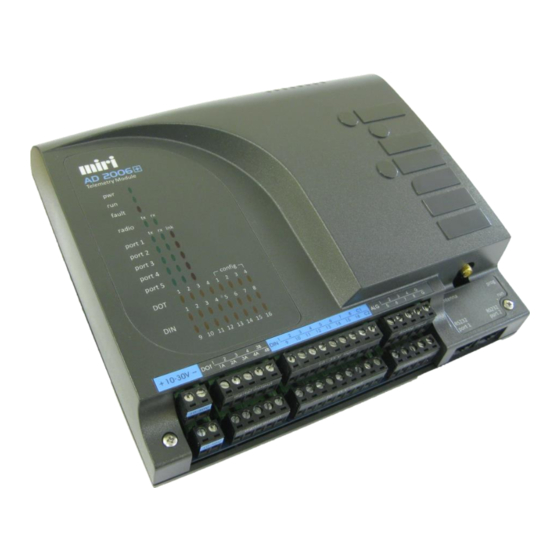
Page 5: General Arrangement
Technical Information General Arrangement LED Indicators The pwr LED should be on at all times when the unit is powered up. The run LED should flash at 2Hz in RUN mode and 4Hz in PROG mode. A fault means that the module has received a bad reply to a message. The tx and rx LEDs reflect the PTT and CD status of the internal radio. -
Page 6: Digital I/O
Digital I/O Digital Inputs There are two different versions of the AD2006+ module with respect to Digital Inputs. There is a low voltage version for nominally 12 or 24 volt inputs, and a high voltage version specifically for 110 volt inputs. The digital inputs are optically isolated to 2.5KV. -
Page 7: Digital Outputs
Digital Outputs Each of the four Digital Outputs may be individually configured as an isolated relay or common emitter transistor. Isolated Relay Configuration (factory default) Common Emitter Configuration With all jumpers J12 - J15 in position A, the module is With all jumpers J12 - J15 in position B, all outputs are configured for 2 SPST and 2 SPDT relay outputs. -
Page 8: Analog I/O
Analog I/O Analog Inputs AD2006+ module has 8 analog input channels as standard. These are configured from the factory as 4-20mA/1-5V. The following options are available by jumper selection: 0-20mA / 0-5V 4-20mA / 1-5V 0-1V Whichever option is selected determines the configuration of all analog input channels. Channels 1 to 8 are configured for current or voltage inputs via jumpers J35 to J42 respectively. -
Page 9: Analog Outputs (Optional)
Analog Outputs (Optional) An analog output board must be installed to utilise this option. This is a factory fitted option. When the analog output option is installed, any of the last four channels can be configured as 4-20mA outputs. ANALOG OUTPUTS – Channel 5-8 Configured as Outputs Note: Ensure that the unit is powered down when moving jumpers. -
Page 10: Communication Options
Communication Options Microhard Nano The standard radio option for an AD2006+ module is an on-board digital radio. This is installed on a ‘Nano’ interface board and is connected to the main PCB via CONN4. All options for the Nano radios are selected in software. There are no hardware jumper settings required for this radio configuration. AD2006+ Rev.11 hardware platform also supports FFSK radio options which are interfaced to the main PCB via the appropriate interface board. -
Page 11: Ports
Ports Port 1 – External Radio - RS232 Port 1 is available for use with an external radio if the module does not have an on-board radio installed. No internal jumper options need be set in order to use the external radio port. Function (view looking into the ext. -
Page 12: Antennas
Antennas It is imperative for the reliable operation of your radio telemetry system that the antennas be installed correctly. It is therefore strongly recommended that the services of qualified radio personnel be used for the antenna installations. The following example is a guide only which shows the salient features relating to the installation of commonly used antennas. -
Page 13: Wiring & Mounting
Wiring & Mounting Wiring Mounting AD2006+ module is installed by means of the clip-in stainless steel mounting bracket supplied with the unit. The module is removed by depressing the small tongue at the bottom of the mounting bracket and sliding the unit upwards. The terminal blocks are removable so that the I/O wiring need not be disturbed if replacing a module in the field.
Need help?
Do you have a question about the AD2006+ and is the answer not in the manual?
Questions and answers