Table of Contents
Advertisement
Quick Links
Advertisement
Table of Contents

Subscribe to Our Youtube Channel
Related Manuals for Autel MaxiCharger DC Compact

Summary of Contents for Autel MaxiCharger DC Compact
- Page 1 Installation and Operation Manual MaxiCharger DC Compact (EU)
- Page 2 All information, specifications and illustrations in this manual are based on the latest information available at the time of printing. Autel reserves the right to make changes at any time without notice. While information of this manual has been carefully checked for accuracy, no guarantee is given for the completeness and correctness of the contents, including but not limited to the product specifications, functions, and illustrations.
-
Page 3: Table Of Contents
CONTENTS USING THIS MANUAL ......................1 ........................1 ONVENTIONS Bold Text ........................1 Notes and Important Message ................... 1 Illustrations ......................1 Revision History ......................1 SAFETY ..........................3 ......................... 3 AFETY ESSAGES ......................3 AFETY NSTRUCTIONS ......................4 ISPOSAL NSTRUCTIONS GENERAL INTRODUCTION .................... - Page 4 Checking the Package ..................... 32 Getting Started ....................... 34 Completing the Installation ..................36 ......................38 OWER UPPLY IRING AC Input Cable Information ..................38 Opening the Door ....................39 Connecting the AC Input Cable ................. 40 ....................42 ONNECTING TO THE NTERNET Via the Ethernet Cable .....................
- Page 5 Measuring the DC Voltage ..................52 ..................53 OCAL ERVICE ORTAL PERATIONS Setting the OCPP Parameters ................... 53 Configuring the Cloud Platform ................53 MAINTENANCE ........................54 ......................54 OUTINE AINTENANCE Residual Current Device Maintenance ............... 54 Cleaning the MaxiCharger ..................55 Cleaning and Replacing the Filter ................
-
Page 6: Using This Manual
Using This Manual This manual provides the procedures for installing and operating of the MaxiCharger DC Compact. Read through this manual and become familiarized with the instructions of the MaxiCharger prior to installation to ensure successful use. This document is intended for these groups:... - Page 7 2.1 Fire protection added 2.2 Disposal instructions added 3.4 Product dimensions added 5. Installation updated 6.3 Emergency stop response added 6.5 Configuring the cloud platform added 2023.07.04 Side cover of the charger updated Most figures updated Technical specifications updated Packing List updated Section 5.3/5.4/5.5 updated Section 6.3 updated V3.1...
-
Page 8: Safety
Safety Instructions The safety messages herein cover situations Autel is aware of. Autel cannot know, evaluate or advise you as to all of the possible hazards. You must be certain that any condition or service procedure encountered does not jeopardize your personal safety. -
Page 9: Disposal Instructions
Protect the wiring inside the MaxiCharger from damage and do not obstruct the wiring when you perform maintenance on the cabinet. Protect the MaxiCharger with safety devices and measures as specified by local rules. Do not install or use this equipment near flammable, explosive, harsh, or combustible materials, chemicals or vapors. -
Page 10: General Introduction
General Introduction The MaxiCharger DC Compact is designed to charge an electric vehicle (hereinafter called EV). Our chargers provide safe, reliable, fast, and smart charging solutions. This MaxiCharger is intended for the DC charging of EVs and is intended for both indoor and outdoor use: ... -
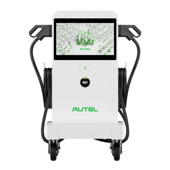
Page 11: Product Overview (Outside)
Product Overview (Outside) Ambient Light Sensor Touchscreen RFID Card Reader POS Payment Device (optional) EV Charging Cable Ethernet Cable Port AC Inlet Hole Vent — each on the right and left side Lock Groove Lifting Handle Bezel... -
Page 12: Product Overview (Inside)
Product Overview (Inside) Equipment Control Unit Communication Control Unit 1 Power Hub AC Contactor (KM2) Surge Protection Device AC Contactor (KM1) Residual Current Breaker with Over-Current (RCBO) Communication Control Unit 2 Energy Meter (PJ1) Energy Meter (PJ2) 48 V Auxiliary Power 24 V Auxiliary Power... -
Page 13: Product Dimensions
Product Dimensions MaxiCharger Front View Side View Pedestal Front View Side View... - Page 14 Trolley Front View Side View...
- Page 15 Pedestal-mounting Front View Side View Unit: mm (inch)
- Page 16 Trolley-mounting Front View Side View Unit: mm (inch)
-
Page 17: Technical Specifications
Technical Specifications Product Information Power Rating Charging Type 40 kW, max. 47 kW Mode 4 Rated/Max. Input AC Current Input Voltage Range 75 A/82 A 400 VAC +10% ~ -10% @ 50Hz Max. Output Current for Outlet A/B DC Output Voltage ... - Page 18 Dimensions (W x D x H) 550 x 265 x 1000 mm User Interface Status Indication LED/APP User Interface Communications Protocols Autel Charge APP OCPP 1.6 JSON Autel Charge Cloud OCPP 2.0.1 (optional) Connectivity User Authentication ...
-
Page 19: Preparation
Preparation Before You Begin Read through this manual prior to installation to familiarize yourself with the installation steps. Ensure the appropriate wiring, circuit protection, and metering are in place at the installation site, according to the specifications, wiring diagrams, and grounding requirements. -
Page 20: Installation Tools
Installation Tools Flathead Screwdriver Hoisting Equipment Socket Wrench (8 mm/10 mm/13 mm/19 mm) Phillips Screwdriver Drill (16 mm) Brush Wire Stripper Cable Lug (Recommended: SC16-8) Voltage Tester Digital Multimeter NOTE ... -
Page 21: Installation
Installation The MaxiCharger can be mounted on a pedestal or a trolley. The installation work shall be carried out after a suitable location is chosen. IMPORTANT Always check local codes to ensure compliance. The guidelines described here are the minimum requirements. -
Page 22: Moving The Maxicharger
Moving the MaxiCharger It is recommended to move the MaxiCharger to the installation site using an appropriate hoisting equipment (crane, straps, and so on). Remove the four screws on the top of the charger using a flathead screwdriver. Set them aside. - Page 23 Install and tighten the four M12 lifting eye bolts into the four holes. Connect the cables of the hoisting equipment to the eye bolts’ lifting loops. DO NOT tilt over 45° when hoisting the MaxiCharger. Move the MaxiCharger to the installation site.
-
Page 24: Installing The Pedestal-Mounted Maxicharger
Installing the Pedestal-mounted MaxiCharger The pedestal-mounted MaxiCharger can be shipped in the following two conditions: MaxiCharger and pedestal unassembled MaxiCharger mounted on pedestal NOTE The “MaxiCharger and pedestal unassembled” means the MaxiCharger and pedestal will be shipped in separate boxes. ... -
Page 25: Checking The Package
Checking the Package Ensure the following items can be found in the package. For MaxiCharger and pedestal unassembled: Lifting Eye Bolt MaxiCharger (M12) 4 PCS Triangle Socket Key Hex Key (6 mm) 2 PCS 1 PC Expansion Bolt Pedestal (M12 x 80) 1 PC 4 PCS Screw (M12 x 30) - Page 26 For MaxiCharger mounted on pedestal: Lifting Eye Bolt Main Unit (M12) 1 PC 4 PCS Torx Screwdriver Hex Key (6 mm) (T25) 1 PC 1 PC Expansion Bolt Triangle Socket Key (M12 x 80) 2 PCS 4 PCS Drilling Template 1 PC...
-
Page 27: Getting Started
Getting Started Step 1: Preparing the conduit Trench and excavate a cable tunnel to accommodate the conduit. The outer diameter of the conduit must not exceed 120 mm. The conduit stub-up should be minimum 100 mm. Pull the conduit and wire up through the exit opening, leaving 600 mm flexible length for the remaining installation activities. - Page 28 Step 2: Drilling holes Place the drilling template on the concrete surface, aligning its central hole with the exit opening. NOTE The “Front” side of the drilling template must face forward. Mark four holes on the concrete surface using a marker. Remove the drilling template. Drill four holes at the marked positions measuring 16 mm in diameter and minimum 80 mm in depth.
- Page 29 Step 3: Mounting a pedestal Screw the four M12 x 80 expansion bolts into the drilled holes. Use a 19 mm socket wrench to remove the threaded bolts (C) and flat washers (B) when the expansion sleeves (A) are stuck. Set them aside.
- Page 30 Loosen the four M5 x 12 screws using the T25 Torx screwdriver to remove the front cover from the pedestal. Set them aside. For MaxiCharger and pedestal unassembled: For MaxiCharger mounted on pedestal:...
- Page 31 Place the pedestal/Lift the main unit (MaxiCharger mounted on a pedestal) onto the mounting location, aligning the central hole with the exit opening. Reinsert the flat washers and threaded bolts in order and tighten them using a 19 mm socket wrench to 45–55 Nm. For MaxiCharger and pedestal unassembled: For MaxiCharger mounted on pedestal:...
- Page 32 Step 4: Mounting the MaxiCharger NOTE The MaxiCharger mounted on pedestal can skip this Step 4. Lift the MaxiCharger onto the pedestal by the hoisting equipment. Position the groove (B) on the back of the MaxiCharger to fit the protrusion (A) of the pedestal as shown below. Ensure the charger is securely attached.
- Page 33 Insert and fasten the two M12 x 30 screws to the bottom holes (A) of the MaxiCharger using a 19 mm socket wrench to secure the MaxiCharger.
- Page 34 Step 5: Organizing the charging cable Take down the rubber rings (A) from the pedestal and remove the two strain reliefs (B) by unscrewing the four M4 nuts using the Phillips screwdriver. Use the strain reliefs to secure the charging cables by screwing the four M4 nuts and tightening them to 1.2 Nm.
-
Page 35: Completing The Installation
Completing the Installation Close and lock the front door by tightening the two M8 hex screws (A) using the hex key. Close the side cover and turn the triangle socket key clockwise to lock the side cover. - Page 36 Reinstall the pedestal’s front cover by screwing the four M5 x 12 screws and tightening them to 2 Nm.
-
Page 37: Installing The Trolley-Mounted Maxicharger
Installing the Trolley-mounted MaxiCharger The trolley-mounted MaxiCharger can be shipped in the following two conditions: MaxiCharger and trolley unassembled MaxiCharger mounted on trolley NOTE The “MaxiCharger and trolley unassembled” means that the MaxiCharger and trolley will be shipped in separate boxes. ... - Page 38 Screw (M12 x 30) Trolley (2 PCS for spare use) 1 PC 4 PCS Industrial Plug (with Cable) 1 PC For the MaxiCharger mounted on trolley: Main Unit Hex Key (6 mm) 1 PC 1 PC Triangle Socket Key 2 PCS...
-
Page 39: Getting Started
Getting Started Use a Phillips screwdriver to loosen the four M5 x 12 screws to remove the front cover of the trolley. Set them aside. - Page 40 Lift the MaxiCharger onto the trolley. Position the groove (B) on the back of the MaxiCharger to fit the protrusion (A) of the trolley as shown below. Ensure the MaxiCharger is securely attached. Remove the four lifting eye bolts and reinstall the top screws.
-
Page 41: Completing The Installation
Completing the Installation Use the strain reliefs which have been installed on the trolley to secure the charging cable and AC input cable. Tighten the M5 nuts using an 8 mm socket wrench. Use the smaller strain relief to secure the Phoenix charging cable. ... - Page 42 Close and lock the front door by tightening the two M8 hex screws using the hex key. Close the side cover and turn the triangle socket key clockwise to lock the side cover. Drape the charging cables and industrial plug cable on the cable holders on the side and the rear respectively.
-
Page 43: Power Supply Wiring
Power Supply Wiring NOTE The MaxiCharger mounted on trolley can skip this section. WARNING Risk of Electric Shock Only a qualified electrician should determine the electrical requirements and connect wires. Ensure the power is off before connecting the wires. IMPORTANT Before connecting the wires, ensure the following requirements are met: ... -
Page 44: Opening The Door
Opening the Door Shift the lock cover (A) on the right side of the MaxiCharger to one side, then insert the triangle socket key into the lock and turn it anti-clockwise to open the side door. Loosen the two M8 hex screws (A) using the hex key and open the front door. -
Page 45: Connecting The Ac Input Cable
Connecting the AC Input Cable NOTE Connect the provided industrial plug (with cable) to the terminal block inside the MaxiCharger for the MaxiCharger and trolley unassembled. Follow the steps below to connect the industrial plug (with cable). Loosen the five M6 x 16 screws using a Phillips screwdriver to remove the insulating barrier (A) and set them aside. - Page 46 Loosen the M6 fastener using a 10 mm socket wrench and connect the PE wire to the PE busbar (A). Reinsert the fastener and tighten it to 6 Nm. Use a 13 mm wrench to loosen the four M8 fasteners and attach the wires to the connectors: ...
-
Page 47: Connecting To The Internet
Connecting to the Internet The MaxiCharger can access the Internet via Ethernet Cable, Wi-Fi or cellular network. The installation process vary among different Internet connections. Select the optimal method to connect the Internet and follow the steps below accordingly. Via the Ethernet Cable NOTE For trolley-mounted MaxiCharger, cellular data or Wi-Fi is preferred to access the Internet for movability. -
Page 48: Via The Cellular Network
Via the Cellular Network Press the button (A) to release the SIM card tray. Insert a SIM card into the tray. Ensure the card is placed correctly. Push the SIM card tray into the slot. -
Page 49: Installing The Upstream Protective Device
Installing the Upstream Protective Device Devices Specifications Options: Dedicated upstream protection RCD (Type A) + MCB device(s) RCBO (Type A) Upstream overcurrent protection Breaker rating should be at least 80 A. breaker, such as RCBO or MCB Recommended: 100 A. Refer to your local rules for (The breaker serves as the main breaker rating. -
Page 50: Operation
Operation Ensure all the installation and wiring are secured and correct, then power on the MaxiCharger. CAUTION Do not touch the inside components of the MaxiCharger while it is powered on. Operate the MaxiCharger only when its door is closed and locked. NOTE In the event of ambient temperature lower than -20 °C, it will take 3–5 minutes for the touchscreen to display when powering on the MaxiCharger. -
Page 51: Standby Mode
Standby Mode After a connector is successfully connected to your EV, the MaxiCharger can automatically recognize the connector, then the corresponding connector’s Authorization Screen will appear. If no operation is performed for a long time on the Authorization Screen, the Standby Screen will appear. -
Page 52: Authorization
Check the surroundings and the MaxiCharger for any abnormalities and damage as well. If the screen displays an error message, DO NOT use the MaxiCharger. Contact Autel Technical Support. When the Authorization Screen appears, you can use any of the following methods to start a charging session. -
Page 53: Start Charging
Start Charging After authorization, the MaxiCharger will set up communication with your EV and necessary safety tests will be performed. Following the safety tests, the charging session will start automatically. Charging You will be informed of the progress during charging. Information about the charging duration, energy, cost, and power will appear on the Charging Screen. -
Page 54: Stop Charging
Normally, you have to authorize again to finish charging, using the same authentication method as was used to start: QR code: Scan the QR code with the Autel Charge app and tap the Stop button on the Charging Screen of the Autel Charge app. ... -
Page 55: Charging Errors
If an error occurs during charging, the Charging Failure screen will appear. The cause and possible solution(s) will display on the screen. Follow the on-screen instructions to resolve the problem, or contact your local dealer or Autel Technical Support. Emergency Stop Response When detecting emergency stop signal sent from the EV during charging, the MaxiCharger will immediately stop DC output. -
Page 56: Powering Down The Maxicharger
Powering down the MaxiCharger Set the upstream breaker which provides the power to the MaxiCharger to OFF and lock it. Make sure that this breaker stays in the OFF position during the procedure. Open the front door. Measure the AC voltage by referring to Voltage. -
Page 57: Measuring The Dc Voltage
Measuring the DC Voltage Use a voltage tester to measure the DC voltage between the output terminals, making sure that all the measured voltages are 0 volt. Power module group output 1- (A) to power module group output 1+ (B) ... -
Page 58: Local Service Portal Operations
Configuring the Cloud Platform Configuring the cloud platform is also needed for the charger. The MaxiCharger supports Autel or a third-party cloud platform. The Autel Charge Cloud, a one-stop charging management solution, is intended to address the needs of many use-cases including commercial, residential, governmental, car dealers, and fleets. -
Page 59: Maintenance
Pass: The RCBO will trip and restore the Test button to its original position. Fail: The RCBO does not trip. Please contact Autel technical support. Do not use the MaxiCharger until the repair is completed. Close the front door after the test is finished. -
Page 60: Cleaning The Maxicharger
Cleaning the MaxiCharger The MaxiCharger is powder-coated. The coating must be kept in good condition. When the MaxiCharger is in a corrosion sensitive environment, superficial rust may appear on welding points. Visible rust has no risk to the integrity of the MaxiCharger. ... - Page 61 To clean or replace the filter Before cleaning and replacing, be sure to stop all charging processes, disconnect the external power supply, and perform the power-off protection. Open the two toggle latches (A) at the bottom of the MaxiCharger to flip the bezel (B) downward.
-
Page 62: Inspection And Maintenance
System self-check for abnormality daily. If any operation abnormality is found, contact your local dealer or Autel technical support promptly. Autel service engineers can check logs, update configurations and programs, and provide remote maintenance services, such as remote management, diagnosis, configuration, and upgrades. -
Page 63: Maintenance Schedule
Maintenance Schedule Item Frequency Actions Check for cracks or ruptures on the Connector Every 3 months connector. Check for cracks or ruptures on the Input Cable Every 3 months cable. Filter Annually Replace the filter. MaxiCharger Every 3 months Clean and check for damage. -
Page 64: Troubleshooting And Service
Troubleshooting and Service Troubleshooting The table below describes the most common faults when operating the MaxiCharger. Contact Autel technical support if the fault encountered is not in this table. Error Error Code Possible Cause Solution It may be caused by... - Page 65 Autel technical frequently, there may be support. an aged key component. Power off the MaxiCharger AC contactor AC contactor fault or line 0x3008 and contact Autel technical stuck aging support. Stop the charge session, power off the MaxiCharger, FPGA fault 0x3010...
-
Page 66: Service
Error Error Code Possible Cause Solution Contact Autel technical Communication Abnormal charging support to identify the fault, error on one 0x3051 module and then clear the fault or charging module replace the module. Contact Autel technical Fan fault with one... - Page 67 www.autelenergy.com...
Need help?
Do you have a question about the MaxiCharger DC Compact and is the answer not in the manual?
Questions and answers