Table of Contents
Advertisement
Available languages
Available languages
Quick Links
ENG | Instruction Manual
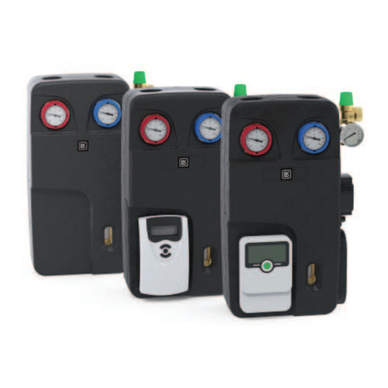
LK 212 Solar Station
PAGE
LANGUAGE
1.
English
3.
Deutsch
5.
Français
7.
Italiano
9.
Suomi
11.
Svenska
TECHNICAL DATA
Voltage
Sensor
Operating temperature
Max. operating pressure
Operating pressure
Safety valve
Media
Media area
Pump
Protection type
Connections
Insulation
FOREWORD
LK 212 SolarStation is a compact dual-pipe solar pump unit with
or without an inbuilt solar heating controller, which transfers heat
from the solar collector to the accumulator tank. The pump unit
contains all the necessary components for safe operation and
control of the solar heating system.
SCOPE OF DELIVERY
•
Valve combination for filling and draining with 2 - 12 l/min
flowmeter and built-in controlling/shutoff valve. Connections:
1" male thread and ¾" female thread. Pipe connections: ¾"
male thread.
•
Safety valve 6 bar with manometer 0 - 10 bar,
G ¾" male thread for expansion tank, ¾" female thread for
drain connection.
•
Ball valves with 1" male thread and ¾" female thread with
built-in thermometer (0-120°C) and non-return valve. Red
knob for supply and blue knob for return. Inbuilt solar heating
controller, applies to the versions where this is included.
1
230 VAC ± 10%, 50 Hz
PT 1000
Supply: Max. 140°C
Return: Max. 110°C
1.0 MPa (10 bar)
0.6 MPa (6 bar)
0.6 MPa (6 bar)
Water - Glycol mixture, max.
50%
2 - 12 l/min
Grundfos UPM3 Solar 25-75 180
Wilo Para ST 25-180/8 IPWM2
IP 20
1" male thread and ¾" female
thread
EPP
www.lkarmatur.com
LK 152 SMARTSOLAR SLL
•
1 sensor cable (PT 1000) for high temperatures, 250°C
•
2 sensor cables (PT 1000), 180°C
LK 152 SMARTSOLAR CS PLUS
•
2 sensor cables (PT 1000) for high temperatures, 250°C
•
2 sensor cables (PT 1000), 180°C
INSTALLATION
Select an appropriate location in the boiler room for the pump unit
and expansion tank. Remove the front.
Note! National rules and safety regulations must be complied
when installing the product.
The pump unit is mounted at a child-safe height so that the solar
heating controller's digital display can be easily used and read.
Ensure that there is room for the expansion tank.
Connect the safety group (6). The expansion tank is connected to
¾" male thread on the safety group (under manometer). Steam
can escape from the safety valve so a heat-resistant overflow pipe
must be connected to the safety valve (7) and guided to a heat-
resistant vessel.
As standard, the solar heating controller has 3 or 4 sensors,
depending on which type of control is used (collector sensor, tank
sensor and additional sensor).
The sensors are mounted according to the installation and
operating instructions for the solar heating controller.
If the sensor cables have to be extended, the cable diameter must
be at least 5 mm.
Note! The sensor cables must not come into direct contact with
pipes, valves or high voltage cables. Use cable ties for instance to
keep them apart.
All pipes connected to the pump unit must be insulated.
Monopropylene glycol is recommended as a heat transfer fluid to
minimise the risk of corrosion to components and thread seals.
Advertisement
Table of Contents

Related Manuals for LK 212

Summary of Contents for LK 212
- Page 1 (collector sensor, tank sensor and additional sensor). FOREWORD LK 212 SolarStation is a compact dual-pipe solar pump unit with The sensors are mounted according to the installation and or without an inbuilt solar heating controller, which transfers heat operating instructions for the solar heating controller.
- Page 2 ENG | Instruction Manual COMMISSIONING and the entire system is filled. The expansion tank’s prepressure is normally 1.5 bar. The Close the return valve (1) when there is no air in the fluid. Con- prepressure must be 0.3 bar higher than the static pressure. It tinue filling until the required operating pressure is reached.
-
Page 3: Technische Daten
(7) anzuschließen und zu einem hitzebeständigen Gefäß zu VORWORT führen. LK 212 ist ein Zweistrang-Antriebspaket mit oder ohne integrier- ten Temperaturdifferenzregler, das die Übertragung von Wärme Im Lieferumfang des Temperaturdifferenzreglers sind standard- von den Sonnenkollektoren zum Warmwasserspeicher regelt. Das mäßig drei oder vier Fühler enthalten, je nach Art der Steuerung,... - Page 4 DE | Bedienungsanleitung INBETRIEBNAHME schließen. Die Befüllung fortsetzen, bis der gewünschte Be- Der Vordruck des Ausdehnungsgefäßes beträgt normalerweise triebsdruck erreicht wird. 1,5 bar. Der Vordruck muss 0,3 bar höher sein als der statische Danach das Befüllventil (4) schließen und die Befüllpumpe Druck.
-
Page 5: Caractéristiques Techniques
AVANT PROPOS raccordé au filetage extérieur 3/4” sur le groupe de sûreté (sous LK 212 est une unité d’entraînement à deux conduites, avec ou le manomètre). De la vapeur peut sortir de la soupape de sûreté sans dispositif automatique de chauffage solaire intégré, qui trans- ;... -
Page 6: Mise En Service
FR | Manuel d’instruction MISE EN SERVICE tes jusqu’à ce que le liquide soit exempt d’air et que tout le La pression d’entrée du vase d’expansion est normalement de système est rempli. 1,5 bar. Cette pression d’entrée doit être supérieure de 0,3 bar à Une fois que le liquide est exempt d’air, fermez la vanne de re- la pression statique. -
Page 7: Dati Tecnici
PREFAZIONE sicurezza (7) e un serbatoio resistente al calore. LK 212 SolarStation è un gruppo di azionamento a due tubi, di- sponibile con o senza centralina integrata per il riscaldamento a La centralina per il riscaldamento a energia solare è fornita di... -
Page 8: Messa In Funzione
IT | Manuale di istruzioni MESSA IN FUNZIONE ricircolo non deve funzionare a secco. Fare scorrere il liquido Normalmente il serbatoio di espansione è precaricato a una pres- nell’intero impianto per almeno 15 minuti finché non è stata sione di 1,5 bar. La pressione di precarica deve essere superiore eliminata tutta l’aria e l’impianto non è... -
Page 9: Tekniset Tiedot
Aurinkolämmitysautomatiikassa on vakiona 3 tai 4 anturia käyte- tystä ohjausjärjestelmästä riippuen (keräinanturi, säiliöanturi ja JOHDANTO lisäanturi). LK 212 on kaksiputkinen ohjauspaketti integroidulla aurinko- Anturit asennetaan aurinkolämmitysautomatiikan käyttöohjeen lämmitysautomatiikalla tai ilman sellaista, joka siirtää lämpöä mukaisesti. aurinkokeräimestä varaajasäiliöön. Ohjauspaketti sisältää kaikki Jos anturikaapeleita pitää... - Page 10 FI | Käyttöopas KÄYTTÖÖNOTTO koko järjestelmää vähintään 15 minuuttia, kunnes nesteessä Paisunta-astian esipaine on normaalisti 1,5 bar. Esipaineen tulee ei ole ilmaa ja koko järjestelmä on täynnä. olla 0,3 bar korkeampi kuin staattinen paine. Se on tarkastettava Kun nesteessä ei ole ilmaa, sulje paluuventtiili (1). Täyttöä ennen järjestelmän täyttöä.
-
Page 11: Teknisk Data
Solvärmeautomatiken har som standard 3 eller 4 stycken medföl- FÖRORD jande givare beroende på vilken styrning som används (kollektorgi- LK 212 är ett tvårörs drivpaket med eller utan integrerad sol- vare, tankgivare samt extra givare). värmeautomatik, som överför värme från solfångare till ackumu- latortank. - Page 12 SE | Instruktionsmanual Alla rör som kopplas till drivpaketet skall isoleras. manuellt enligt manual för solvärmeautomatiken. Obs! Cirku- För att minimera risken för korrosion och frätning av komponenter lationspumpen får inte gå torr. Spola genom hela systemet i och gängtätningar rekommenderas monopropylenglykol som minst 15 minuter tills vätskan är fri från luft och hela syste- värmebärare.
-
Page 13: Capacity Diagram
ENG | Instruction Manual LK 212 SOLARSTATION WITH LK 152 SMARTSOLAR SLL LK 212 SOLARSTATION WITH LK 152 SMARTSOLAR CS LK 212 SOLARSTATION CAPACITY DIAGRAM 343,4 www.lkarmatur.com... - Page 14 ENG | DE | FR | IT | FI | SE WILO PARA QUICK START GUIDE | SCHNELLSTARTANLEITUNG | GUIDE DE DÉMARRAGE RAPIDE | GUIDA RAPIDA | PIKAOPAS | SNABBGUIDE WILO PARA SELF CONTROL / INSTALLATION | EIGENKONTROLLE / INSTALLATION | AUTOCONTRÔLE/IN STALLATION | CONTROLLO AUTOMATICO / INSTALLAZIONE | ITSETARKASTUS / ASENNUS | SJÄLVKONTROLL / INSTALLATION WILO PARA SELF CONTROL / SETTING | EIGENKONTROLLE / EINSTELLUNGEN | AUTOCONTRÔLE/RÉGLAGES | CONTROLLO...
- Page 15 Circulating pump | Umwälzpumpe | Circulateur | Pompa di ricircolo | Kiertovesipumppu | Cirkulationspump 182675 LK 152 SmartSolar SLL 182735 LK 152 SmartSolar CS Plus 187325 Bracket | Konsole | Console | Collettore | Konsoli | Konsol 095475 EPP Insulation | EPP Isolierung | EPP Isolation | EPP Isolmento | EPP eriste | EPP Isolering 095473 Ball valve red | Kugelventil, Rot | Vanne à...
- Page 16 LK ARMATUR AB www.lkarmatur.com LK ARMATUR DEUTSCHLAND GMBH www.lkarmatur.de...
Need help?
Do you have a question about the 212 and is the answer not in the manual?
Questions and answers