Advertisement
Quick Links
Advertisement

Related Manuals for LK MS-RE Series

Summary of Contents for LK MS-RE Series
- Page 1 MS-RE Solar Inverter User Manual MS-RE 1 and MS-RE 2...
- Page 2 MS-RE Solar Inverter The MS-RE Solar Inverter range, is designed for locations having unreliable or limited access to electricity, to provide a reliable and affordable energy access solution. It is designed to supply continuous energy from solar and grid based on availability. The Inverter is customized to prioritize solar energy over grid supply.
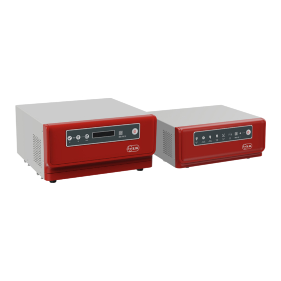
- Page 3 MS-RE Solar Inverter Front Panel Description: MS-RE 1 ON-OFF MAINS SOLAR MAINS POWER SWITCH CHARGING CHARGING SAVER BATTERY OVER SYSTEM QR Code LOAD 1. ON-OFF SWITCH Press and hold for 2 seconds for the device ON/OFF function. 2. MAINS ON Indicates mains status.
- Page 4 MS-RE Solar Inverter Front Panel Description: MS-RE 2 ON-OFF SWITCH DISPLAY SAVE QR Code 1. ON-OFF SWITCH Press and hold for 2 seconds for the device ON/OFF function and the backlight ON/OFF function. 2. LCD DISPLAY Displays the various parameters on the LCD screen. 3.
- Page 5 MS-RE Solar Inverter Configuration Settings: MS-RE 2 To change the settings using LCD and switches: Press OK and UP at the same time for 1 second to enter settings. Use UP switch to navigate to the required setting. Press OK to view the parameter setting options. Use UP switch to scroll to the required option.
- Page 6 HOMAYA SOLAR HYBRID SYSTEM MS-RE Solar Inverter Back Panel Description: MS-RE 1 DC BATTERY INPUT - 12 V PANEL 12V AC OUTPUT AC INPUT 230V~50Hz S.NO. MADE IN INDIA MODEL NO. CAUTION: ENSURE CORRECT TERMINALS OF BATTERY 1. Mains Fuse Connects to the input of the MS-RE Solar Inverter.
- Page 7 MS-RE Solar Inverter Back Panel Description: MS-RE 2 DC BATTERY INPUT - 24 V AC OUTPUT PANEL 24V AC MCB AC INPUT 230V~50Hz S.NO. MADE IN INDIA MODEL NO. CAUTION: ENSURE CORRECT TERMINALS OF BATTERY 1. Mains input Cable (Input 230 V~ 50 Hz) Connects input AC supply (the commercial supply) to the solar inverter.
- Page 8 MS-RE Solar Inverter Display Parameter: MS-RE 2 Power On Screen UPS Mode Screen Loop Screen 2 Screen 3 Screen 4 Screen 1 Screen 6 Screen 5 Mains Mode Screen Loop Screen 2 Screen 3 Screen 1 Screen 4 Screen 6 Screen 5 BATT: Battery...
- Page 9 MS-RE Solar Inverter Solar Generation History Screen 2 Screen 3 Screen 1 Screen 4 Screen 6 Screen 5 Press to select screen 4 from the loop Long press till you here a beep Press to view the solar power generation history of day 2–day 7 Long press till the beep sound comes to an exit...
-
Page 10: Unpacking And Placement
MS-RE Solar Inverter Packaging Contents and Product Dimensions MS-RE 1 Solar Inverter 320 mm MAINS SOLAR MAINS POWER BATTERY OVER MS - RE 1 CHARGING CHARGING SAVER LOAD Spare fuse (10 A) (313 mm) 12 mm 302 mm MS-RE 1 Solar inverter Warranty card 320 mm MS-RE 2 Solar Inverter... - Page 11 MS-RE Solar Inverter Product Typical Installation: MS-RE 1 12 V PV Panel up to 850 Wp DC BATTERY INPUT - 12 V PANEL 12V AC OUTPUT AC INPUT 230V~50Hz S.NO. MADE IN INDIA MODEL NO. CAUTION: ENSURE CORRECT TERMINALS OF BATTERY 12 V (1x12 V) 80Ah to 200 Ah Product Typical Installation: MS-RE 2...
-
Page 12: Battery Installation
MS-RE Solar Inverter Battery Installation Installation Diagrams NOTE Battery connections should be performed by qualified personnel with appropriate training. No responsibility is assumed by LTLK for consequences arising due to noncompliance. HAZARD OF ELECTRIC SHOCK, EXPLOSION, OR ARC FLASH DANGER HAZARD OF ELECTRIC SHOCK, EXPLOSION, OR ARC FLASH Ensure correct polarity of batteries are connected to the terminals. - Page 13 HOMAYA SOLAR HYBRID SYSTEM MS-RE Solar Inverter Connection Diagram with Grid supply for MS-RE 1 Solar Inverter Distribution Box Input Grid Supply Earth Terminal Neutral Terminal Mains Input Supply DC BATTERY INPUT - 12 V PANEL 12V AC OUTPUT AC INPUT 230V~50Hz S.NO.
- Page 14 MS-RE Solar Inverter Installation Steps • Switch OFF the power supply to the distribution point where the MS-RE Solar Inverter has to be connected. • Check the building wiring. NOTE: Improper wiring may not prevent the MS-RE Solar Inverter from operating but may limit its protection capability. Also, improper building wiring may result in equipment damage that is not covered under warranty.
- Page 15 MS-RE Solar Inverter Recommended Solar Panel Mounting Orientation "Northern Hemisphere" "Southern Hemisphere" Panel stand mounting hole Panel stand mounting hole Always Keep in Mind for Best Performance and Safety Panel direction True south Panel angle tilt As per site latitude Panel to inverter wire length Up to 10 meters Panel installation area...
- Page 16 MS-RE Solar Inverter Power Flow Diagrams for MS-RE 1 Solar Inverter Solar Mode PV Module PV Module Mode : SOLAR Mode : SOLAR Power Saver Power Saver - OFF Mains Charging - ON <=11.5 V ** <=12.8V & solar is not available for 12hrs. PV Module PV Module **In case of a tubular battery under power saver OFF condition, battery is less than or equal to 11.0 V.
- Page 17 MS-RE Solar Inverter Mode : SOLAR + GRID PV Module PV Module Mode : SOLAR + GRID Power Saver - OFF Power Saver - ON Mains Charger RESTORE >=13.5V >=14.0V = Float <=12.5V & PV Module PV Module PV Module <5A >=10A >=5A...
- Page 18 MS-RE Solar Inverter Power Flow Diagrams for MS-RE 2 Solar Inverter Solar + Grid Mode PV Module PV Module Mode : SOLAR + GRID Mode : SOLAR + GRID Power Saver - OFF Power Saver - OFF Mains Charging - OFF PV Module >=26V <=23V**...
- Page 19 MS-RE Solar Inverter PV Module Mode : GRID + SOLAR No Power Saver Mains Charger RESTORE PV Module <5A PV Module Solar Mode PV Module PV Module Mode : SOLAR Mode : SOLAR Power Saver Power Saver - OFF <=23 V ** <=25.4V &...
-
Page 20: Troubleshooting
MS-RE Solar Inverter Troubleshooting MS-RE 1 Solar Inverter Problem Possible Cause (s) Action Recommended The mains supply is normal but: Line cord plug is not connected correctly. Connect the line cord plug correctly. b The Mains ON indicator is OFF. The solar inverter is either working on battery Dead wall socket. - Page 21 MS-RE Solar Inverter Protection Screens: MS-RE 2 Display Screen Possible Cause (s) Action Recommended Battery low Recharge the battery Abnormal battery function Contact installer Inverter overload Reduce the connected load Inverter output short circuit Check the load for short circuit High temperature Contact installer Inverter shutdown due to no load...
-
Page 22: Technical Specifications
MS-RE Solar Inverter Technical Specifications Product MS-RE 1 MS-RE 2 Product VA Rating 850 VA 1500 VA Input Battery Voltage 12 V 24 V 850 Wp, 1500 Wp, Solar Panel 18 V - 25 V VOC 36 V - 60 VOC Mains Mode Mains High Voltage Disconnect 290 V ±... - Page 23 MS-RE Solar Inverter Product MS-RE 1 MS-RE 2 Front Panel Display Indication Thermistor Open/Short Indication Mains ON LED and Over Load LED steady Output Feedback Open/Reverse Mains ON LED and Over Load LED blinking Mains ON LED and Mains Charging LED DC Over Voltage Indication blinking Battery Charging Through Solar...
- Page 24 February - 2023 Version 01...
Need help?
Do you have a question about the MS-RE Series and is the answer not in the manual?
Questions and answers