
Related Manuals for ASROCK A520M-ITX/ac


Summary of Contents for ASROCK A520M-ITX/ac
- Page 1 Questo manuale d’istruzione è fornito da trovaprezzi.it. Scopri tutte le offerte per AsRock A520M ITX/ac cerca il tuo prodotto tra le migliori offerte di Schede Madri...
- Page 2 (including damages for loss of profits, loss of business, loss of data, interruption of business and the like), even if ASRock has been advised of the possibility of such damages arising from any defect or error in the documentation or product.
- Page 3 You are also entitled to have the goods repaired or replaced if the goods fail to be of acceptable quality and the failure does not amount to a major failure. If you require assistance please call ASRock Tel : +886-2-28965588 ext.123 (Standard International call charges apply) The terms HDMI®...
- Page 4 CE Warning This device complies with directive 2014/53/EU issued by the Commision of the European Community. This equipment complies with EU radiation exposure limits set forth for an uncontrolled environment. This equipment should be installed and operated with minimum distance 20cm between the radiator &...
-
Page 5: Table Of Contents
Chapter 1 Introduction Package Contents Specifications Motherboard Layout I/O Panel WiFi-802.11ac Module and ASRock WiFi 2.4/5 GHz Antennas 11 Chapter 2 Installation Installing the CPU Installing the CPU Fan and Heatsink Installing Memory Modules (DIMM) Expansion Slot (PCI Express Slot) - Page 6 3.3.3 BIOS & Drivers 3.3.4 Setting ASRock Polychrome SYNC Chapter 4 UEFI SETUP UTILITY Introduction 4.1.1 UEFI Menu Bar 4.1.2 Navigation Keys Main Screen OC Tweaker Screen Advanced Screen 4.4.1 CPU Configuration 4.4.2 Onboard Devices Configuration 4.4.3 Storage Configuration 4.4.4 ACPI Configuration 4.4.5 Trusted Computing...
-
Page 7: Chapter 1 Introduction
ASRock’s website without further notice. If you require technical support related to this motherboard, please visit our website for specific information about the model you are using. You may find the latest VGA cards and CPU support list on ASRock’s website as well. ASRock website http://www.asrock.com. -
Page 8: Specifications
4333(OC)/4266(OC)/4200(OC)/4133(OC)/4000 (OC)/3866(OC)/3800(OC)/3733(OC)/3600(OC)/3466 (OC)/3200/2933/2667/2400/2133 ECC & non-ECC, un-buffered memory* * Please refer to Memory Support List on ASRock’s website for more information. (http://www.asrock.com/) * Please refer to page 23 for DDR4 UDIMM maximum frequency support. • Max. capacity of system memory: 64GB • Supports Extreme Memory Profile (XMP) memory modules... - Page 9 A520M-ITX/ac Expansion • 1 x PCI Express 3.0 x16 Slot (PCIE1: x16 mode)* Slot * AMD Ryzen series CPUs (Matisse) supports PCIe riser cards to extend x8/x8 slots * Supports NVMe SSD as boot disks • 1 x Vertical M.2 Socket (Key E) with the bundled WiFi- 802.11ac module (on the rear I/O)
- Page 10 SATA3 6.0 Gb/s module and M.2 PCI Express module up to Gen3 x4 (32 Gb/s)* * Supports NVMe SSD as boot disks * Supports ASRock U.2 Kit Connector • 1 x RGB LED Header * Supports in total up to 12V/3A, 36W LED Strip • 1 x Addressable LED Header...
- Page 11 • Fan Multi-Speed Control: CPU, Chassis/Water Pump Fans • Voltage monitoring: +12V, +5V, +3.3V, CPU Vcore • Microsoft® Windows® 10 64-bit Certifica- • FCC, CE tions • ErP/EuP ready (ErP/EuP ready power supply is required) * For detailed product information, please visit our website: http://www.asrock.com...
- Page 12 Please realize that there is a certain risk involved with overclocking, including adjusting the setting in the BIOS, applying Untied Overclocking Technology, or using third-party overclocking tools. Overclocking may affect your system’s stability, or even cause damage to the components and devices of your system. It should be done at your own risk and expense.
-
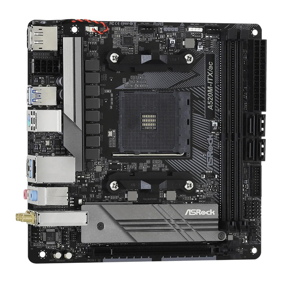
Page 13: Motherboard Layout
A520M-ITX/ac 1.3 Motherboard Layout BAT1 ADDR_LED1 RGB_LED1 CHA_FAN1 CPU_FAN1 ATX12V1 USB 3.2 Gen1 T: USB1 B: USB2 USB 3.2 Gen1 T: USB3_3 B: USB3_TC_1 RoHS M2_WIFI1 A520 CLRCMOS1 HD_AUDIO1 SPEAKER1 CHA_FAN2/WP PCIE1... - Page 14 Description CPU Fan Connector (CPU_FAN1) Addressable LED Header (ADDR_LED1) RGB LED Header (RGB_LED1) Chassis/Water Pump Fan Connector (CHA_FAN1/WP) 2 x 288-pin DDR4 DIMM Slots (DDR4_A1, DDR4_B1) ATX Power Connector (ATXPWR1) SATA3 Connectors (SATA3_1_3) SATA3 Connectors (SATA3_2_4) USB 3.2 Gen1 Header (USB3_4_5) System Panel Header (PANEL1) USB 2.0 Header (USB_3_4) Clear CMOS Jumper (CLRCMOS1)
-
Page 15: I/O Panel
A520M-ITX/ac 1.4 I/O Panel No. Description No. Description USB 2.0 Ports (USB_12)* USB 3.2 Gen1 Type-A Port (USB3_3) LAN RJ-45 Port** USB 3.2 Gen1 Type-C Port (USB3_TC_1) Line In (Light Blue)*** PS/2 Mouse/Keyboard Port Front Speaker (Lime)*** USB 3.2 Gen1 Type-A Port (USB3_1_2) Antenna Ports DisplayPort 1.4... - Page 16 *** Function of the Audio Ports in 7.1-channel Configuration: Port Function Light Blue (Rear panel) Rear Speaker Out Lime (Rear panel) Front Speaker Out Pink (Rear panel) Central /Subwoofer Speaker Out Lime (Front panel) Side Speaker Out...
-
Page 17: Wifi-802.11Ac Module And Asrock Wifi 2.4/5 Ghz Antennas
A520M-ITX/ac 1.5 WiFi-802.11ac Module and ASRock WiFi 2.4/5 GHz Antennas WiFi-802.11ac + BT Module This motherboard comes with an exclusive WiFi 802.11 a/b/g/n/ac + BT v4.2 module (pre-installed on the rear I/O panel) that offers support for WiFi 802.11 a/b/g/n/ ac connectivity standards and Bluetooth v4.2. - Page 18 WiFi Antennas Installation Guide Step 1 Prepare the WiFi 2.4/5 GHz Antennas that come with the package. Step 2 Connect the two WiFi 2.4/5 GHz Antennas to the antenna connectors. Turn the antenna clock- wise until it is securely connected. Step 3 Set the WiFi 2.4/5 GHz Antenna as shown in the illustration.
-
Page 19: Chapter 2 Installation
A520M-ITX/ac Chapter 2 Installation This is a Mini-ITX form factor motherboard. Before you install the motherboard, study the configuration of your chassis to ensure that the motherboard fits into it. Pre-installation Precautions Take note of the following precautions before you install motherboard components or change any motherboard settings. -
Page 20: Installing The Cpu
2.1 Installing the CPU Unplug all power cables before installing the CPU. - Page 21 A520M-ITX/ac...
-
Page 22: Installing The Cpu Fan And Heatsink
2.2 Installing the CPU Fan and Heatsink After you install the CPU into this motherboard, it is necessary to install a larger heatsink and cooling fan to dissipate heat. You also need to spray thermal grease between the CPU and the heatsink to improve heat dissipation. Make sure that the CPU and the heatsink are securely fastened and in good contact with each other. - Page 23 A520M-ITX/ac...
- Page 24 Installing the AM4 Box Cooler SR2...
- Page 25 A520M-ITX/ac...
- Page 26 *The diagrams shown here are for reference only. The headers might be in a different position on your motherboard.
- Page 27 A520M-ITX/ac Installing the AM4 Box Cooler SR3...
- Page 29 A520M-ITX/ac +12V *The diagrams shown here are for reference only. The headers might be in a different position on your motherboard.
-
Page 30: Installing Memory Modules (Dimm)
2.3 Installing Memory Modules (DIMM) This motherboard provides two 288-pin DDR4 (Double Data Rate 4) DIMM slots, and supports Dual Channel Memory Technology. 1. For dual channel configuration, you always need to install identical (the same brand, speed, size and chip-type) DDR4 DIMM pairs. 2. - Page 31 A520M-ITX/ac The DIMM only fits in one correct orientation. It will cause permanent damage to the motherboard and the DIMM if you force the DIMM into the slot at incorrect orientation.
-
Page 32: Expansion Slot (Pci Express Slot)
2.4 Expansion Slot (PCI Express Slot) There is 1 PCI Express slot on the motherboard. Before installing an expansion card, please make sure that the power supply is switched off or the power cord is unplugged. Please read the documentation of the expansion card and make necessary hardware settings for the card before you start the installation. -
Page 33: Jumpers Setup
A520M-ITX/ac 2.5 Jumpers Setup The illustration shows how jumpers are setup. When the jumper cap is placed on the pins, the jumper is “Short”. If no jumper cap is placed on the pins, the jumper is “Open”. Clear CMOS Jumper... -
Page 34: Onboard Headers And Connectors
2.6 Onboard Headers and Connectors Onboard headers and connectors are NOT jumpers. Do NOT place jumper caps over these headers and connectors. Placing jumper caps over the headers and connectors will cause permanent damage to the motherboard. System Panel Header Connect the power (9-pin PANEL1) button, reset button and... - Page 35 A520M-ITX/ac Serial ATA3 Connectors These four SATA3 (SATA3_1_3: connectors support SATA see p.7, No. 7) data cables for internal (SATA3_2_4: storage devices with up to see p.7, No. 8) 6.0 Gb/s data transfer rate. USB 2.0 Headers There is one header on...
- Page 36 Chassis Water Pump Fan This motherboard Connectors provides two 4-Pin water (4-pin CHA_FAN1/WP) cooling chassis fan (see p.7, No. 4) connector. If you plan to connect a 3-Pin chassis FAN_SPEED_CONTROL CHA_FAN_SPEED water cooler fan, please FAN_VOLTAGE connect it to Pin 1-3. (4-pin CHA_FAN2/WP) FAN_VOLTAGE (see p.7, No.
- Page 37 A520M-ITX/ac RGB LED Header RGB header is used to connect (4-pin RGB_LED1) RGB LED extension cable which 12V G R (see p.7, No. 3) allows users to choose from vari- ous LED lighting effects. Caution: Never install the RGB LED cable in the wrong orienta- tion;...
- Page 38 2.7 M.2_SSD (NGFF) Module Installation Guide (M2_1) The M.2, also known as the Next Generation Form Factor (NGFF), is a small size and versatile card edge connector that aims to replace mPCIe and mSATA. The Ultra M.2 Socket (M2_1) supports M Key type 2280 M.2 SATA3 6.0 Gb/s module and M.2 PCI Express module up to Gen3 x4 (32 Gb/s).
- Page 39 A520M-ITX/ac Step 3 Before installing a M.2 (NGFF) SSD module, please loosen the screws to remove the M.2 heatsink. *Please remove the protective films on the bottom side of the M.2 heatsink before you install a M.2 SSD module. Step 4 Align and gently insert the M.2...
- Page 40 TS256GMTS400 Transcend SATA3 TS512GMTS600 Transcend SATA3 TS512GMTS800 V-Color SATA3 VLM100-120G-2280B-RD V-Color SATA3 VLM100-240G-2280RGB V-Color SATA3 VSM100-240G-2280 V-Color SATA3 VLM100-240G-2280B-RD SATA3 WDS100T1B0B-00AS40 SATA3 WDS240G1G0B-00RC30 For the latest updates of M.2_SSD (NFGG) module support list, please visit our website for details: http://www.asrock.com...
-
Page 41: Chapter 3 Software And Utilities Operation
A520M-ITX/ac Chapter 3 Software and Utilities Operation 3.1 Installing Drivers The Support CD that comes with the motherboard contains necessary drivers and useful utilities that enhance the motherboard’s features. Running The Support CD To begin using the support CD, insert the CD into your CD-ROM drive. The CD automatically displays the Main Menu if “AUTORUN”... -
Page 42: Asrock Motherboard Utility (A-Tuning)
3.2.1 Installing ASRock Motherboard Utility (A-Tuning) ASRock Motherboard Utility (A-Tuning) can be downloaded from ASRock Live Update & APP Shop. After the installation, you will find the icon “ASRock Mother- board Utility (A-Tuning)“ on your desktop. Double-click the “ASRock Motherboard Utility (A-Tuning)“... - Page 43 A520M-ITX/ac OC Tweaker Configurations for overclocking the system. System Info View information about the system. *The System Browser tab may not appear for certain models.
- Page 44 Settings Configure ASRock ASRock Motherboard Utility (A-Tuning). Click to select "Auto run at Windows Startup" if you want ASRock Motherboard Utility (A-Tuning) to be launched when you start up the Windows operating system.
-
Page 45: Asrock Live Update & App Shop
Double-click on your desktop to access ASRock Live Update & APP Shop utility. *You need to be connected to the Internet to download apps from the ASRock Live Update & APP Shop. 3.3.1 UI Overview Category Panel Hot News... -
Page 46: Apps
3.3.2 Apps When the "Apps" tab is selected, you will see all the available apps on screen for you to download. Installing an App Step 1 Find the app you want to install. The most recommended app appears on the left side of the screen. The other various apps are shown on the right. - Page 47 A520M-ITX/ac Step 3 If you want to install the app, click on the red icon to start downloading. Step 4 When installation completes, you can find the green "Installed" icon appears on the upper right corner. To uninstall it, simply click on the trash can icon...
- Page 48 Upgrading an App You can only upgrade the apps you have already installed. When there is an available new version for your app, you will find the mark of "New Version" appears below the installed app icon. Step 1 Click on the app icon to see more details. Step 2 Click on the yellow icon to start upgrading.
-
Page 49: Bios & Drivers
A520M-ITX/ac 3.3.3 BIOS & Drivers Installing BIOS or Drivers When the "BIOS & Drivers" tab is selected, you will see a list of recommended or critical updates for the BIOS or drivers. Please update them all soon. Step 1 Please check the item information before update. Click on to see more details. -
Page 50: Setting
3.3.4 Setting In the "Setting" page, you can change the language, select the server location, and determine if you want to automatically run the ASRock Live Update & APP Shop on Windows startup. - Page 51 A520M-ITX/ac...
-
Page 52: Asrock Polychrome Sync
3.4 ASRock Polychrome SYNC ASRock Polychrome SYNC is a lighting control utility specifically designed for unique indi- viduals with sophisticated tastes to build their own stylish colorful lighting system. Simply by connecting the LED strip, you can customize various lighting schemes and patterns, including Static, Breathing, Strobe, Cycling, Music, Wave and more. - Page 53 A520M-ITX/ac Connecting the Addressable RGB LED Strip Connect your Addressable RGB LED strip to the Addressable LED Header (ADDR_LED1) on the motherboard. ADDR_LED1 DO_ADDR VOUT 1. Never install the RGB LED cable in the wrong orientation; otherwise, the cable may be damaged.
- Page 54 ASRock Polychrome SYNC Utility Now you can adjust the RGB LED color through the ASRock Polychrome SYNC Utility. Download this utility from the ASRock Live Update & APP Shop and start coloring your PC style your way! Drag the tab to customize your preference.
-
Page 55: Chapter 4 Uefi Setup Utility
A520M-ITX/ac Chapter 4 UEFI SETUP UTILITY 4.1 Introduction This section explains how to use the UEFI SETUP UTILITY to configure your system. You may run the UEFI SETUP UTILITY by pressing <F2> or <Del> right after you power on the computer, otherwise, the Power-On-Self-Test (POST) will continue with its test routines. -
Page 56: Navigation Keys
4.1.2 Navigation Keys Use < > key or < > key to choose among the selections on the menu bar, and use < > key or < > key to move the cursor up or down to select items, then press <Enter>... -
Page 57: Main Screen
A520M-ITX/ac 4.2 Main Screen When you enter the UEFI SETUP UTILITY, the Main screen will appear and display the system overview. -
Page 58: Oc Tweaker Screen
4.3 OC Tweaker Screen In the OC Tweaker screen, you can set up overclocking features. Because the UEFI software is constantly being updated, the following UEFI setup screens and descriptions are for reference purpose only, and they may not exactly match what you see on your screen. - Page 59 A520M-ITX/ac CCD1 CCX0 Frequency (MHz) Use this item to adjust CCX0 Frequency. CCX1 Frequency (MHz) Use this item to adjust CCX1 Frequency. SoC/Uncore OC Voltage(VID) Specify the SoC/Uncore voltage (VDD_SOC) in mV to support memory and Infinity Fabric overclocking. VDD_SOC also determines the GPU voltage on processors with integrated graphics.
- Page 60 Infinity Fabric Frequency and Dividers AMD Overclocking Setup Set Infinity Fabric frequency (FCLK). Auto: FCLK = MCLK. Manual: FCLK must be less than or equal to MCLK for best performance in most cases. Latency penalties are incurred if FCLK and MCLK are mismatched, but sufficiently high MCLK can negate or overcome this penalty.
- Page 61 A520M-ITX/ac Load User Default Load previously saved user defaults. Save User UEFI Setup Profile to Disk Save current UEFI settings as an user default profile to disk. Load User UEFI Setup Profile to Disk Load previously saved user defaults from the disk.
-
Page 62: Advanced Screen
4.4 Advanced Screen In this section, you may set the configurations for the following items: CPU Configuration, Onboard Devices Configuration, Storage Configuration, ACPI Configuration, Trusted Computing , AMD PBS and AMD CBS. Setting wrong values in this section may cause the system to malfunction. UEFI Configuration Active Page on Entry Select the default page when entering the UEFI setup utility. -
Page 63: Cpu Configuration
A520M-ITX/ac 4.4.1 CPU Configuration PSS Support Use this to enable or disable the generation of ACPI_PPC, _PSS, and _PCT objects. NX Mode Use this to enable or disable NX mode. SVM Mode When this is set to [Enabled], a VMM (Virtual Machine Architecture)can utilize the additional hardware capabilities provided by AMD-V. -
Page 64: Onboard Devices Configuration
4.4.2 Onboard Devices Configuration Turn On Onboard LED in S5 Turn on/off the LED in the ACPI S5 state. SR-IOV Support Enable/disable the SR-IOV (Single Root IO Virtualization Support) if the system has SR-IOV capable PCIe devices. UMA Frame buffer Size (Only for processor with integrated graphics) This item allows you to set the size of the UMA frame buffer. - Page 65 A520M-ITX/ac WAN Radio Configure the WiFi module's connectivity. BT On/Off Enable/disable the bluetooth. PS2 Y-Cable Enable the PS2 Y-Cable or set this option to Auto.
-
Page 66: Storage Configuration
4.4.3 Storage Configuration SATA Mode AHCI: Supports new features that improve performance. RAID: Combine multiple disk drives into a logical unit. SATA Hot Plug Enable/disable the SATA Hot Plug function. -
Page 67: Acpi Configuration
A520M-ITX/ac 4.4.4 ACPI Configuration Suspend to RAM It is recommended to select auto for ACPI S3 power saving. Deep Sleep Configure deep sleep mode for power saving when the computer is shut down. We recommend disabling Deep Sleep for better system compatibility and stability. -
Page 68: Trusted Computing
4.4.5 Trusted Computing Security Device Support Enable or disable BIOS support for security device. -
Page 69: Amd Pbs
A520M-ITX/ac 4.4.6 AMD PBS The AMD PBS menu accesses AMD specific features. -
Page 70: Amd Cbs
4.4.7 AMD CBS The AMD CBS menu accesses AMD specific features. -
Page 71: Tools
A520M-ITX/ac 4.5 Tools Easy RAID Installer Easy RAID Installer helps you to copy the RAID driver from the support CD to your USB storage device. After copying the drivers please change the SATA mode to RAID, then you can start installing the operating system in RAID mode. -
Page 72: Hardware Health Event Monitoring Screen
4.6 Hardware Health Event Monitoring Screen This section allows you to monitor the status of the hardware on your system, including the parameters of the CPU temperature, motherboard temperature, fan speed and voltage. CPU FAN1 Setting Select a fan mode for CPU Fan 1, or choose Customize to set 5 CPU temperatures and assign a respective fan speed for each temperature. - Page 73 A520M-ITX/ac CHA_FAN2/WP Switch Select CHA_FAN2 or Water Pump mode. Chassis Fan 2 Control Mode Select PWM mode or DC mode for Chassis Fan 2. Chassis Fan 2 Setting Select a fan mode for Chassis Fan 2, or choose Customize to set 5 CPU temperatures and assign a respective fan speed for each temperature.
-
Page 74: Security Screen
4.7 Security Screen In this section you may set or change the supervisor/user password for the system. You may also clear the user password. Supervisor Password Set or change the password for the administrator account. Only the administrator has authority to change the settings in the UEFI Setup Utility. Leave it blank and press enter to remove the password. -
Page 75: Boot Screen
A520M-ITX/ac 4.8 Boot Screen This section displays the available devices on your system for you to configure the boot settings and the boot priority. Boot From Onboard LAN Allow the system to be waked up by the onboard LAN. Setup Prompt Timeout Configure the number of seconds to wait for the setup hot key. - Page 76 CSM (Compatibility Support Module) Enable to launch the Compatibility Support Module. Please do not disable unless you’re running a WHCK test. Launch PXE OpROM Policy Select UEFI only to run those that support UEFI option ROM only. Select Legacy only to run those that support legacy option ROM only. Select Do not launch to not execute both legacy and UEFI option ROM.
- Page 77 A520M-ITX/ac AddOn ROM Display Enable AddOn ROM Display to see the AddOn ROM messages or configure the AddOn ROM if you've enabled Full Screen Logo. Disable for faster boot speed.
-
Page 78: Exit Screen
4.9 Exit Screen Save Changes and Exit When you select this option the following message, “Save configuration changes and exit setup?” will pop out. Select [OK] to save changes and exit the UEFI SETUP UTILITY. Discard Changes and Exit When you select this option the following message, “Discard changes and exit setup?”... - Page 79 Contact Information If you need to contact ASRock or want to know more about ASRock, you’re welcome to visit ASRock’s website at http://www.asrock.com; or you may contact your dealer for further information. For technical questions, please submit a support request form at http://www.asrock.com/support/tsd.asp...
- Page 80 DECLARATION OF CONFORMITY Per FCC Part 2 Section 2.1077(a) Responsible Party Name: ASRock Incorporation Address: 13848 Magnolia Ave, Chino, CA91710 Phone/Fax No: +1-909-590-8308/+1-909-590-1026 hereby declares that the product Product Name : Motherboard A520M-ITX/ac Model Number : Conforms to the following speci cations:...
- Page 81 EU Declaration of Conformity For the following equipment: Motherboard (Product Name) A520M-ITX/ac / ASRock (Model Designation / Trade Name) ASRock Incorporation (Manufacturer Name) 2F., No.37, Sec. 2, Jhongyang S. Rd., Beitou District, Taipei City 112, Taiwan (R.O.C.) (Manufacturer Address) EMC —Directive 2014/30/EU (from April 20th, 2016)
Need help?
Do you have a question about the A520M-ITX/ac and is the answer not in the manual?
Questions and answers