Table of Contents
Advertisement
Quick Links
™
Fiber Defender FD508
User Manual
© Copyright 2014, Fiber SenSys® all rights reserved. No part of this publication
may be reproduced or transmitted in any form or by any means, electronic or
mechanical, including photocopy, recording, or any information stora ge and
retrieval system, without permission in writing from Fiber SenSys®, Inc., 2925 NW
Aloclek Drive, Suite 120, Hillsboro, Oregon 97124, USA.
Confidential – Limited Distribution
PM-ENG-040 Rev F
Advertisement
Table of Contents

Related Manuals for FIBER SENSYS Fiber Defender FD508

Summary of Contents for FIBER SENSYS Fiber Defender FD508
- Page 1 Fiber Defender FD508 User Manual © Copyright 2014, Fiber SenSys® all rights reserved. No part of this publication may be reproduced or transmitted in any form or by any means, electronic or mechanical, including photocopy, recording, or any information stora ge and retrieval system, without permission in writing from Fiber SenSys®, Inc., 2925 NW...
- Page 2 This manual is provided by Fiber SenSys Inc. While reasonable efforts have been taken in the preparation of this material to ensure its accuracy, Fiber SenSys Inc. makes no express or implied warranties of any kind with regard to the documentation provided herein.
-
Page 3: Table Of Contents
Table of contents Introduction ......................4 Safety information ....................5 Safety terms ....................5 Electrical safety ....................5 Covers and panels ..................5 Inspection ....................... 6 Laser radiation ....................6 Fiber-handling precautions................6 FCC rules ....................... 7 The Sensing Fiber ....................8 Fiber Optic Sensing .................. -
Page 4: Introduction
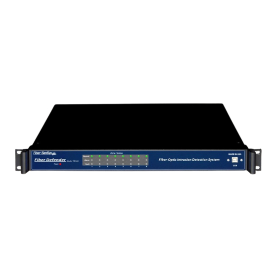
(alarm), or if the fiber is cut (fault). Figure 1-1. Front view of the FD508 APU. Fiber Defender FD508 User Manual... -
Page 5: Safety Information
There are no user-serviceable parts inside the APU. To avoid personal injury, do not remove any of the APU’s covers or panels. The product warranty is void if the factory seal is broken. Do not operate the product unless the covers and panels are installed. Fiber Defender FD508 User Manual... -
Page 6: Inspection
Inspection The FD508 APU should be inspected for shipping damage. If any damage is found, notify Fiber SenSys and file a claim with the carrier. Save the shipping container for possible inspection by the carrier. Laser Radiation The FD508 APU is a Class 1 laser product, as defined by IEC 60825-1 and CFR 21 subchapter J. -
Page 7: Fcc Rules
• Increase the separation between the equipment and receiver. • Connect the equipment into an outlet on a circuit different from that to which the receiver is connected. • Consult the dealer or an experienced radio/TV technician for help. Fiber Defender FD508 User Manual... -
Page 8: The Sensing Fiber
(APC) fiber optic connectors. PC and UPC connectors should not be used. For more information about fiber optic connectors, refer to the fiber optics application note: AN-SM-007 Fiber Optics. Fiber Defender FD508 User Manual... -
Page 9: System Configuration
Multimode End-Of-Line (MMEOL) terminator. Fiber SenSys provides a trunk cable that can carry the insensitive lead-in fibers to all the zones. At points where a zone is desired, specialized tools can be used to cut into the trunk cable to expose one of the insensitive lead-in fibers which is then spliced to sensing fiber (see figure 3-1);... - Page 10 However, these zones must be connected to the APU in a specific order, as determined by the Port Assignment software. For more on the Port Assignment software, see the application note: AN-SM-023 Port Assignment Wizard. Fiber Defender FD508 User Manual...
-
Page 11: The Alarm Processing Unit (Apu)
1. Eight optical ports for the fiber optic sensors that go to each zone. 2. Relay outputs for each zone. 3. Optical test port (for initial setup). Not used after commissioning the system. 4. Tamper input. 5. TCP/IP port via RJ45 connector. 6. DC power input jack. Fiber Defender FD508 User Manual... -
Page 12: Installing The Apu Into The Rack
The APU comes with a rack-mounting that consists of two rack-mounting handles and screws for attaching them to the APU. Attach the handles to the APU, and then mount the APU into the rack by the rack-mounting handles. Fiber Defender FD508 User Manual... -
Page 13: Tuning The Zones
1. Define the tuning parameters for each HyperZone. 2. Assign zones to HyperZones. 3. Write parameters to the APU. 4. Rename zones. 5. Assign a device name to the APU. 6. Define the XML report interval. Fiber Defender FD508 User Manual... - Page 14 The number of HyperZones can be as high as 8 (in which case each zone is in its own HyperZone) or as low as one (in which case all the zones have the same tuning parameters). Fiber Defender FD508 User Manual...
-
Page 15: Hyperzone Tuning
With the HyperZone selected, change the value of any tuning parameter using either the arrow keys or by typing a new value into the associated box and pressing Enter. If the allowable range is exceeded, 500 Series View automatically changes the entry to the closest allowed value. Fiber Defender FD508 User Manual... - Page 16 (PD), while minimizing the nuisance alarm rate (NAR). For detailed information about these tuning parameters, see the Fiber SenSys application note on tuning parameters titled: AN-SM-008 Setting the Tuning Parameters.
- Page 17 HyperZones on the APU. This may take several seconds depending on how many HyperZones are in the system. The values written from the file to the APU for the currently selected HyperZone are also displayed on the APU Parameters screen. Fiber Defender FD508 User Manual...
-
Page 18: Assigning A Device Name
500 Series View pauses momentarily while establishing contact with the new zone, which is then highlighted. A progress bar in the lower right corner of the screen shows the display being updated in real time. Fiber Defender FD508 User Manual... - Page 19 Time mode. In Spectral mode the display shows the sensor data as a function of frequency (see figure 5-5). In Time mode, the display shows sensor data as a function of time (see figure 5-6) Figure 5-5. The 500 Series View Realtime screen Fiber Defender FD508 User Manual...
- Page 20 Figure 5-6. Realtime mode, showing data as a function of time (each sample point equals about 0.8 msec.) Fiber Defender FD508 User Manual...
-
Page 21: Integrating The Apu Into The Security System
It can also receive device- configuration commands in XML format. The processes involved in integrating the APU into a security system are described in detail in the networking application note, AN-SM-009 APU Networking. Fiber Defender FD508 User Manual... -
Page 22: Testing And Certification
If the PD is too low, tune the system to be more sensitive. Repeat this procedure for each installed zone on the secured perimeter. Additional simulated intrusions might include cutting the fence or digging/crawling beneath it. Fiber Defender FD508 User Manual... -
Page 23: Maintenance
Connect power to the new APU, and repeat the processes described in the chapters in this manual on tuning, integration, and testing. For troubleshooting assistance, contact Fiber SenSys Technical Support Service: telephone, 1- 503-374-9896; email, support@fibersensys.com; or go to the Fiber SenSys website, www.fibersensys.com. -
Page 24: Appendix A. Product Specifications
The sensing fiber comes pre-installed in conduit, for directly attaching to the fence using wire ties. The maximum length of pre-installed sensing fiber in conduit is 800 meters. If you require longer lengths, please contact the factory. Fiber Defender FD508 User Manual... -
Page 25: Appendix B. Auxiliary Software Features
Alarm Status screen. In this way, you can quickly verify that the system is functioning properly following configuration and calibration. To see detailed information about each of these auxiliary software features, see the application note on FD508 auxiliary features, AN-SM-010 Auxiliary SW Features. Fiber Defender FD508 User Manual... -
Page 26: Appendix C. Warranty Information
C. Fiber SenSys liability is limited to the repair or replacement of the product only, and not the costs of installation, removal, or damage to user’s property or other liabilities. If Fiber SenSys is unable to repair or replace a non-conforming product, it may offer a refund of the amount paid to Fiber SenSys for such product in full satisfaction of its warranty obligation. -
Page 27: Appendix D. Referenced Documents
AN-SM-025 500 Series Optional Accessories AN-SM-035 FD500 Series – Standard Installation Instructions AN-SM-036 FD500 Series – Site Design and Assessment Note: It is possible to download these documents online from the Fiber Sensys web page: www.fibersensys.com Fiber Defender FD508 User Manual...
Need help?
Do you have a question about the Fiber Defender FD508 and is the answer not in the manual?
Questions and answers