Table of Contents
Advertisement
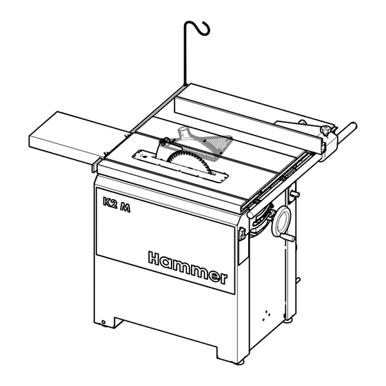
K2 M - Part 2/2
Circular saws
Download your local language
CZ
DA
DE
EN
ES
FR
HU
IT
NL
PL
RO
RU
SV
http://fg.am/ba-manuals
Keep this manual to hand and in good condition for future reference.
Please read this operating manual carefully before using the machine.
Translation of the original operating instructions
Operating instructions
510010-901-2, 1, en_GB
Advertisement
Table of Contents

Related Manuals for Hammer K2 M


Summary of Contents for Hammer K2 M
- Page 1 K2 M - Part 2/2 Circular saws Download your local language http://fg.am/ba-manuals Keep this manual to hand and in good condition for future reference. Please read this operating manual carefully before using the machine. Translation of the original operating instructions...
- Page 2 FELDER KG KR-Felder-Straße 1,A-6060 HALL in Tirol, AUSTRIA Telephone: +43 5223 5850 0 Email: info@felder-group.com Internet: www.felder-group.com © 2023...
-
Page 3: Table Of Contents
K2 M - Part 2/2 Table of contents Table of contents Adjustments and tool changes.......... - Page 4 Table of contents General maintenance procedures......... 36 3.4.1 Clean the machine thoroughly.
-
Page 5: Adjustments And Tool Changes
K2 M - Part 2/2 Adjustments and tool changes Adjustments and tool changes Rip fence 1.1.1 Positioning the rip fence Fig. 1: Positioning the rip fence Rip fence scale Indicator Thumb screw (clamping of the rip fence) Scale clamping screw Switch off the machine. -
Page 6: Change The Fence Plate (Guide) Over
Adjustments and tool changes 1.1.2 Change the fence plate (guide) over Fig. 2: Mount the guide in a flat position Thumb screw (clamping of the fence plate) Guide (fence plate) Groove Clamping rail Scale indicator When the fence plate is mounted flat, the distance to the saw blade changes. By moving the scale indicator, the change in the cutting width can be corrected. -
Page 7: Remove The Rip Fence
K2 M - Part 2/2 Adjustments and tool changes 1.1.3 Remove the rip fence Fig. 3: Remove rip fence Thumb screw 1 (clamping of the fence plate) Clamping screw 2 (clamping the rip fence) Fence support bar When processing large panels or when carrying out maintenance work it may be necessary to remove the rip fence. - Page 8 Adjustments and tool changes Fig. 4: Mount the "Sägeboy" auxiliary fence Sägeboy auxiliary fence (Art.-No. 01.0.022) Guide rail Thumb screws Fence plate Template (mounted to the workpiece) Tenoning hood and auxiliary fence "Sägeboy" On machines without overhead saw guard, covered cuts and grooving work may be carried out if the "Sägeboy"...
-
Page 9: Setting The Height/Angle Of Cut (Standard Configuration)
K2 M - Part 2/2 Adjustments and tool changes Setting the height/angle of cut (standard configuration) Fig. 5: Adjusting the cutting height / cutting angle Handwheel height adjustment Handwheel angle adjustment Clamping lever cutting angle adjustment Scale cutting angle Adjusting the cutting height Only set the cutting height to the height actually required. -
Page 10: Tool Change
Adjustments and tool changes Tool change 1.3.1 General information relating to saw blades and grooving tools NOTICE Danger of collision when using grooving tools Damage to the grooving tools and machine table. − Do not adjust the 90° angle when working with grooving tooling. -
Page 11: Prepare To Change Tooling
K2 M - Part 2/2 Adjustments and tool changes 1.3.2 Prepare to change tooling Fig. 7: Prepare to change tooling Thumb screws Saw guard Riving knife Insert board Position the saw aggregate in the 90° position (cutting angle 0°) and move to the uppermost position. -
Page 12: Establish Operational Readiness
Adjustments and tool changes 1.3.3 Establish operational readiness Operational readiness when using saw blades Fig. 8: Operational readiness - Saw blade work Insert board Saw guard Spring catches Thumb nut Operational readiness The saw blade only operates if the limit switch inside the machine frame has not been actuated by the locking system. - Page 13 K2 M - Part 2/2 Adjustments and tool changes Operational readiness when using grooving tools Fig. 9: Operational readiness - grooving tool Insert board (Art.-no. 500-07-206) Flat head screws M6x16 Tenoning hood "Sägeboy" Grooving tool Operational readiness The saw blade only operates if the limit switch inside the machine frame has not been actuated by the locking system.
-
Page 14: Changing The Saw Blade
Adjustments and tool changes Changing the saw blade 1.4.1 Installing the saw blade in the machine Note For precision cuts, we recommend you to use the smallest saw blade possible. See technical data for authorised saw blades. Fig. 10: Change the saw blade.eps Riving knife Locking pins Saw arbour... -
Page 15: Loosen / Adjust Riving Knife
K2 M - Part 2/2 Adjustments and tool changes Secure the saw arbour against rotation. Insert the locking pin into the hole on the circular saw table. Turn the circular saw shaft until the locking pin engages. Loosen the clamping screw with a fork wrench. - Page 16 Adjustments and tool changes NOTICE Incorrectly adjusted distance between the saw blade and riving knife Material damage and possible malfunction with covered cuts. − The gap between the riving knife and saw blade must be between 3 and 8 mm. −...
-
Page 17: Fit /Change The Riving Knife
K2 M - Part 2/2 Adjustments and tool changes 1.4.3 Fit /change the riving knife Fig. 12: Fitting the riving knife Clamping screw Riving knife Serrated washers Bolts Saw blade Tool: ● Combination wrench 17 mm Loosen the clamping screw. - Page 18 Adjustments and tool changes Correct selection of the riving knife Fig. 13: Suitable riving knife for the saw blade Riving knife thickness (d) Saw tooth width (D) Saw blade body (S) The riving knife has to be adapted to the thickness of the saw blade. The thickness of the riving knife must be between that of the saw blade body and the width of the saw tooth.
-
Page 19: Remove The Riving Knife
K2 M - Part 2/2 Adjustments and tool changes 1.4.4 Remove the riving knife Fig. 15: Remove the riving knife Clamping screw Riving knife holder Riving knife WARNING Serious injury arising from contact with the rotating saw blade If working without a riving knife, the workpiece could become jammed after the saw blade. -
Page 20: Grooving Tools
Adjustments and tool changes Grooving tools 1.5.1 Retooling to an operation with grooving tools Fig. 16: Rear flange / riving knife holder / insert board Insert board Rear flange Flange for circular saw blades Riving knife removed WARNING Sharp and hot tool cutting edges Cuts and burns due to sharp and hot tools. -
Page 21: Clamping The Grooving Tool
K2 M - Part 2/2 Adjustments and tool changes 1.5.2 Clamping the grooving tool Fig. 17: Insert grooving tool Flange for grooving tools Clamping screw grooving tool (M10x40 L) Grooving tool Grooving tool Part 1 Grooving tool Part 2 Spacer washers... - Page 22 Adjustments and tool changes Secure the saw arbour against rotation. Insert the locking pin into the hole on the circular saw table. Turn the circular saw shaft until the locking pin engages. WARNING Flying pieces Severe injuries and damage to property. ●...
-
Page 23: Removing The Grooving Tools - Retool To A Saw Blade Operation
K2 M - Part 2/2 Adjustments and tool changes Inserting the insert board for grooving tool. Position the insert board in the machine table from above. If necessary, correct the position of the insert board with the grub screws. Screw in 7 countersunk screws with an Allen key. - Page 24 Adjustments and tool changes Secure the saw arbour against rotation. Insert the locking pin into the hole on the circular saw table. Turn the circular saw shaft until the locking pin engages. Loosen the clamping screw with a fork wrench. Left screw thread, loosen by turning clockwise.
-
Page 25: Fitting And Adjusting Circular Saw Guard
K2 M - Part 2/2 Prepare the machine to operate. ⮫ ‘Operational readiness when using saw blades’ on page 12 Fitting and adjusting circular saw guard Fig. 21: Adjust circular saw guard Riving knife (recess) Thumb nut Hood stud Distance (inclination - min. 2 mm / max. 4 mm) -
Page 26: Switch On / Switch Off / Shutdown Due To An Emergency Stop
● Keep tools for processing short and narrow workpieces close at hand (e.g. push grip, pushing stick, workpiece holder). Switch on / switch off / shutdown due to an emergency stop WARNING Insufficient preparation Severe injuries and damage to property −... -
Page 27: Working Techniques
K2 M - Part 2/2 Working techniques 2.3.1 Working area WARNING Ejected workpieces / tool parts Risk of injury due to ejected workpieces and workpiece parts (e.g. cutting tools, branches, trimmings). Injury due to kickback from cut workpiece parts. −... -
Page 28: Prohibited Working Methods
● Covered cuts / rebate on the parallel cutting fence. ● Covered cuts / grooves on the parallel cutting fence with grooving tools. 2.3.3 Prohibited working methods The following working processes are prohibited on this panel saw: ● All work techniques without the use of the parallel cutting fence, crosscut fence or trimming unit. -
Page 29: Longitudinal Cut / Cutting Of Strips
K2 M - Part 2/2 On machines without extraction system control, switch on the extraction system. Only switch the machine on once the workpiece has been placed in the correct position. Feed the workpiece evenly past the saw blade, keeping your fingers balled into a fist. -
Page 30: Cutting Short, Narrower Workpieces
WARNING Rotating saw blade Severe injury caused by contact with a rotating saw blade. − Never place your hands on the workpiece in the danger zone. − Push the workpiece past the saw blade with the push stick. Take note of general procedures for permitted working methods. If required and only when cutting strips: Change the fence plate (guide) on the rip fence over on to the narrow guide edge. -
Page 31: Crosscutting With The Crosscut And Rip Fence
K2 M - Part 2/2 Crosscut fence Slot in machine table Take note of general procedures for permitted working methods. Move the rip fence as far away as possible from the saw blade. Attach the off-cut deflector to the machine in such a way that the sawed off pieces do not collide with the rising part of the saw blade. -
Page 32: Covered Cuts (Sägeboy Auxiliary Fence)
Feed the workpiece evenly past the saw blade, keeping your fingers balled into a fist. Pull the workpiece a few millimetres away from the saw blade and pull the crosscut fence back into the starting position. 2.3.8 Covered cuts (Sägeboy auxiliary fence) Fig. -
Page 33: Working With Grooving Tools (Sägeboy Auxiliary Fence)
K2 M - Part 2/2 2.3.9 Working with grooving tools (Sägeboy auxiliary fence) Fig. 29: Working with grooving tools Grooving tool, no riving knife Sägeboy auxiliary fence (accessory) Template (mounted to the workpiece) NOTICE Collision between machine components Material damage when swivelling the saw unit. -
Page 34: Maintenance
Maintenance Adjust the rip fence so that the edge of the saw blade is flush with the Sägeboy guide rail. �� The Sägeboy guide rail also serves as a fence for sawing with templates. On machines with sliding table: Lock the sliding table into the centre position. If an eccentric clamp is used, mill out the groove using the sliding table. -
Page 35: Preparations For Maintenance Work / Removing The Cover Plate
K2 M - Part 2/2 Maintenance Preparations for maintenance work / Removing the cover plate Instructions to maintenance technicians If the maintenance technician has to check whether they have carried out their work correctly or troubleshoot whilst the machine is running, the following instruc- tions must be followed: ●... -
Page 36: Cleaning And Lubricating
Maintenance Remove the cover plate from the front side: Loosen the wing nut inside the machine. The wing nut can be reached from the rear side of the machine. Push the cover plate upwards and remove it from the front. To reassemble, follow the instructions in the reverse order. -
Page 37: Belt Tension
K2 M - Part 2/2 Maintenance Clean the machine of dust, shavings, waste material and other contami- nants. Cleaning the table surface and the guide tracks. Remove any resin residue. Clean rip fence inc. guiding shaft and check that they work properly. -
Page 38: Check Dust Extractor
Maintenance Lubricate height guides with normal machine grease. Spread the grease with a brush onto the guide. Position the saw unit in the lowest and then the most uppermost position. Prepare the machine to operate. ⮫ Chapter 1.3.3 ‘Establish operational readiness’ on page 12 3.4.4 Check dust extractor Check dust extractor for any damage... - Page 39 K2 M - Part 2/2 Maintenance Push the [Emergency stop]. Machine stops immediately. Continue with next step. Machine does not stop immediately. If present: Switch off [Main switch] (position "O" / "OFF"). Disconnect the machine from the mains power supply.
-
Page 40: Check Effectiveness Of Safety Devices (End Switch)
Maintenance Switch machine off with the red [Stop] button. The saw shaft with clamped saw blade must be brought to a complete stop within 10 seconds. Machine comes to a standstill within 10 seconds. Checking the time for the machine to come to a stop com- pleted. -
Page 41: Lubricating The Circular Saw Height Spindle And Tilting Spindle
K2 M - Part 2/2 Maintenance Press the green [Start]-button on the control panel. �� The machine will not switch on (insert board removed). The saw blade only operates if the limit switch inside the machine frame has not been actuated (insert board must be inserted). -
Page 42: Checking/Changing The Circular Saw Drive Belt
Maintenance Tilt the saw unit to a 45° position and then back to a 90° position. Position the saw unit in the lowest and then the most uppermost position. Place the cover plate in position and hang it on the screws. The cover plate must be in contact with the machine chassis on all sides. -
Page 43: Replacing The Drive Belt
K2 M - Part 2/2 Maintenance 3.5.2 Replacing the drive belt Fig. 35: Replacing the drive belt Guard plate Screws M6x10 Locking nut Tightening screw Tool: ● Spanner 13 mm ● Allen key 4 mm Tilt the saw to the approx. 30° position. Move the saw blade to the lower- most position. -
Page 44: Re-Tensioning The Drive Belt
Maintenance Mount the front cover plate. Mount the rear cover plate. �� The respective cover plate must be in contact with the machine chassis on all sides before tightening it. 3.5.3 Re-tensioning the drive belt NOTICE Do not over-tension the drive belt An over-tightened drive belt can tear or cause bearing damage. -
Page 45: Troubleshooting
K2 M - Part 2/2 Troubleshooting Troubleshooting What to do in the event of a malfunction WARNING Improper troubleshooting Severe injuries and damage to property − Troubleshooting may only be carried out by authorised, trained personnel who are familiar with how to operate the machine and are in strict observance of all safety instructions. - Page 46 Troubleshooting Fault description Cause Remedy Safety limit switch without func- Fault in the electrical system Contact Felder-Group service tion centre. Machine cannot be switched Fault in the electrical system / Disconnect the machine from the [Emergency stop] - command mains power supply. chain Contact Felder-Group service centre.
-
Page 47: Adjust The Height Of The Rip Fence Above The Machine Table
K2 M - Part 2/2 Troubleshooting Adjust the height of the rip fence above the machine table Fig. 37: Readjusting the rip fence height Rip fence Locking nut Adjustment screw Allen key 4 mm Tool: ● Allen key 4 mm ●... - Page 48 Troubleshooting Fig. 38: Freecut preparation Riving knife and saw guard Saw blade ø253 mm cutting saw teeth high running saw teeth X1 Rip fence setting X2 Free cut adjustment Prepare the machine for adjustment Switch off the machine and secure it against being switched on again. Disconnect the machine from the mains power supply.
- Page 49 K2 M - Part 2/2 Troubleshooting Correcting the rip fence angle (adjust free cut) Fig. 39: Adjust free cut Locking nut Adjustment point (table extension) front adjusting nut X1 Rip fence setting rear locking nut X2 Free cut adjustment A Adjustment point (machine table) Tool: ●...
-
Page 50: Correct Crosscut Fence Settings
Troubleshooting Correct crosscut fence settings Fig. 40: Crosscut fence - Angle correction Upper adjustment screw Lower adjustment screw Locking nut Clamping lever Fence plate Left adjustment screws Right adjustment screws 0°-angle adjustment (readjust) Tool: ● Angle gauge ● Combination wrench 10 mm ●... - Page 51 K2 M - Part 2/2 Troubleshooting Check the setting by making a 2-sided sample cut Fig. 41: Sample cut - Crosscut fence angle First cut (reference cut) Rotate the workpiece in a clockwise direction Second cut (control cut) Tool: ●...
-
Page 52: Attachment
Attachment Width adjustment of the guide rail Fig. 42: Crosscut fence - Adjust the rail width Ease of operation Guide rail Play (guide rail / machine table) First grub screw Grub screws two to five Tool: ● Allen key 2 mm The width of the guide rail can be adjusted to the width of the guiding groove using the 5 grub screws. -
Page 53: Disposal
K2 M - Part 2/2 Attachment If unauthorised spare parts are fitted into the machine, all warranty, service, compensation and liability claims against the manufacturer and their contractors, dealers and representatives will be rejected. Use genuine spare parts The original spare parts that have been authorised for use are listed in a separate spare parts catalogue, enclosed in the docu- mentation package supplied with the machine. - Page 54 Attachment ENVIRONMENT Disposing of batteries Batteries are subject to special waste treatment regulations and must be disposed of in accordance with locally enforced regula- tions. The improper handling of batteries, can due to their potentially dangerous substances, have a negative environmental effect and consequences for human health.
- Page 56 FELDER KG KR-Felder-Straße 1,A-6060 HALL in Tirol, AUSTRIA Telephone: +43 5223 5850 0 Email: info@felder-group.com Internet: www.felder-group.com...
Need help?
Do you have a question about the K2 M and is the answer not in the manual?
Questions and answers
SALVE. VOLEVO SAPERE SE CI STA QUALCHE MODO PER AUMENTARE LO SPAZIO SUL LATO SINISTRO DEL BANCO.SE ESISTE QUALCHE PROLUNGA. IN PIÚ VOLEVO SAPERE SE LE SCALA NATURE NEL PIANO SONO COMPATIBILI **** ALTRI GONIOMETRI AD ESEMPIO INCRA O ALTRI. GRAZIE