
Subscribe to Our Youtube Channel
Related Manuals for Hammer N2-35


Summary of Contents for Hammer N2-35
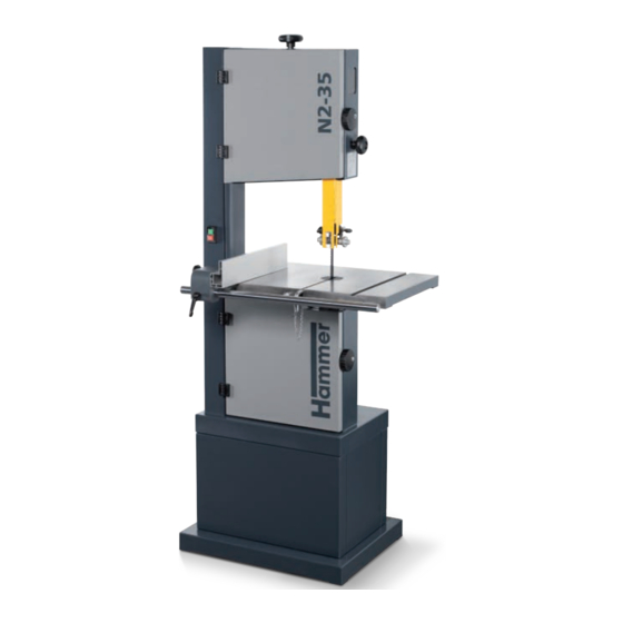
- Page 1 Operating Manual GER = Original operating manual language Other languages = Translation of the original operating manual Bandsaw N2-35 Keep this manual handy and in good condition for continual reference!
- Page 2 Bandsaw N2-35 Attention!: The machine must be inspected immediately upon arrival. If the machine has been damaged during transport, or if any parts are missing, a written record of the problems must be submitted to the forwarding agent and a damage report compiled. Also be sure to notify your supplier immediately.
- Page 3 Bandsaw N2-35...
-
Page 4: Table Of Contents
Bandsaw N2-35 Content 1 General ....................6 2 Safety ....................8 3 Declaration of Conformity ..............12 4 Specifications ..................14 5 Setting up the machine ................ 18 6 Transport, packaging and storage ............20... - Page 5 Bandsaw N2-35 Content 7 Setup and installation ................24 8 Operation ................... 32 9 Service ....................42 10 Faults ....................46 11 Electrical circuit diagram ..............48 12 Spare parts ..................50...
-
Page 6: General
Bandsaw N2-35 General 1 General 1.1 Symbol legend Warning! Risk of injury or death! This symbol marks instructions that must be followed in order to avoid harm to one‘s health, injuries, perma- nent impairment or death! Warning! Danger! Electric current! This symbol warns of potentially dangerous situations relating to electric current. - Page 7 Bandsaw N2-35 General 1.4 Liability and warranty 1.5 Warranty notice 1.6 Spare parts Attention! Risk of material damage! Non genuine, counterfeit or faulty spare parts may result in damage, cause malfunction or complete break- down of the machine. Note: The original spare parts that have been authorised for use are listed in a separate spare parts catalo- gue, enclosed in the documentation package supplied with the machine.
-
Page 8: Safety
Bandsaw N2-35 Safety 2 Safety 2.1 Intended use Attention! Risk of material damage! Machining materials other than wood is only permitted with the express written consent of the manufacturer. Operational safety is guaranteed only when the machine is used for the intended purposes. - Page 9 Bandsaw N2-35 Safety 2.3 Making changes and modifications to the machine 2.4 Responsibilities of the operator 2.5 Personnel requirements 2.6 Work safety...
- Page 10 Bandsaw N2-35 Safety 2.7 Personal protective equipment Persons with long hair who are not wearing a hairnet are not permitted to work on or with the machine! It is prohibited to wear gloves while working on or with the machine.
- Page 11 Bandsaw N2-35 Safety 2.9 Other risks Warning! Risk of injury! Even if the safety measures are complied with, there are still certain associated risks that must be considered when working on the machine: General safety rules: • • • •...
-
Page 12: Declaration Of Conformity
Bandsaw N2-35 Declaration of Conformity 3 Declaration of Conformity Felder KG KR-Felder-Straß 1, 6060 Hall in Tirol, AUSTRIA Bandsaw HAMMER N2-35 2006/42/EC 2014/30/EU EN 1807-1:2013 EN ISO 12100:2010 EN 60204-1:2018 CEPROM® S.A. Product Certification Body NB 1802 Str.Fântânele f.n RO-440237 Satu Mare... - Page 13 Bandsaw N2-35 Declaration of Conformity Felder KG KR-Felder-Straß 1, 6060 Hall in Tirol, AUSTRIA Bandsaw HAMMER N2-35 S.I. 2008/1597 S.I. 2016/1091 EN 1807-1:2013 EN ISO 12100:2010 EN 60204-1:2018...
-
Page 14: Specifications
Bandsaw N2-35 Specifications 4 Specifications 4.1 Dimensions and weight Fig. 4-1: Total size Machine N2-35 Bandsaw N2-35... - Page 15 Bandsaw N2-35 Specifications 4.2 Operation and storage conditions 4.3 Electrical connection Machine Alternating-current motor Three-phase current motor N2-35 *) S6 = operation under load and intermittent service; 40% = relative operating factor 4.4 Dust Extractors Fig. 4-2: Connection ports...
- Page 16 Bandsaw N2-35 Specifications 4.5 Noise emission Note: To keep the noise emission as low as possible, always use sharpened tools and operate the machine at the correct speed. Do not overload the machine! It is safer and performs better if operated within its power range.
- Page 17 Bandsaw N2-35 Specifications...
-
Page 18: Setting Up The Machine
Bandsaw N2-35 Setting up the machine 5 Setting up the machine 5.1 Overview " & Fig. 5-1: Overview " &... - Page 19 Bandsaw N2-35 Setting up the machine 5.2 Data plate Fig. 5-2: Data plate 5.3 Safety break switches " " Fig. 5-3: Lock system 5.4 Automatic braking system Warning! Risk of injury! In the event of a power supply failure, the electric brake is deactivated. The tool can therefore not come to a complete stop within 10 seconds.
-
Page 20: Transport, Packaging And Storage
Bandsaw N2-35 Transport, packaging and storage 6 Transport, packaging and storage 6.1 Safety instructions Attention! Risk of material damage! The machine can be damaged or destroyed if it is subjected to improper handling during transport. Warning! Risk of injury! There is a risk of injury as a result of falling parts while transporting, loading or unloading the machine. - Page 21 Bandsaw N2-35 Transport, packaging and storage 6.4 Storage Store packed items only under the following conditions 6.5 Transport Attention! Risk of material damage! Transport the machine according to the enclosed transport and assembly instructions! The machine must not be lifted by the work table, sliding table or base! Ropes, belts and chains may only be fastened to the base of the machine.
- Page 22 Bandsaw N2-35 Transport, packaging and storage 6.5.2 Transport with a crane Attention! Risk of material damage!: Do not lift the machine by its work table, extension frames or hand- wheels. Align the straps correctly and check that the machine is properly supported. The machine must be raised slow- ly and very carefully to prevent the load from slipping.
- Page 23 Bandsaw N2-35 Transport, packaging and storage...
-
Page 24: Setup And Installation
Bandsaw N2-35 Setup and installation 7 Setup and installation 7.1 Safety instructions Warning! Risk of injury!: Improper assembly and installation can lead to serious physical injury or equip- ment damage. For this reason, this work may only be carried out by authorised, trained personnel who are familiar with how to operate the machine and in strict observance of all safety instructions. - Page 25 Bandsaw N2-35 Setup and installation 7.2.1 Assemble machine frame (Option) Warning! Heavy dead weights can easily cause an injury To facilitate assembly, ensure the presence of a minimum of one additional people. Note: During the assembly of the machine frame, first loosely connect all parts.
- Page 26 Bandsaw N2-35 Setup and installation 7.2.2 Attaching the band saw to the machine frame Warning! Heavy dead weights can easily cause an injury To facilitate assembly, ensure the presence of a minimum of one additional people. Note: If the machine stand is not mounted on the machine frame, the machine must be placed on a stable and level surface at least 390 mm high.
- Page 27 Bandsaw N2-35 Setup and installation 7.2.3 Setting up the work table / Angle adjustment " " Fig. 7-4: Work table Angle adjustment: 90° to saw band run " Fig. 7-5: 90° to saw band run " Fig. 7-6: 90° to the saw band back...
- Page 28 Bandsaw N2-35 Setup and installation 7.2.4 Assembly - Rip fence " " Height adjustment - Fence rail: Fig. 7-7: Rip fence X1=X2=18 mm " " Fig. 7-8: Height adjustment - Fence rail Setting the rip fence: > X < X "...
- Page 29 Bandsaw N2-35 Setup and installation 7.2.5 Positioning and levelling the machine Note: There are 4 threaded holes located in the base plate of the machine where the levelling screws supplied with the machine can be screwed into. (optional) " Fig. 7-10: Floor mounting...
- Page 30 The electrical outlet must have the appropriate socket (for a three-phase alternating current motor, CEE). Note: Do not open the machine's switch box unless you have the express consent of the Hammer service department Violating this stipulation shall render the right to make claims under the warranty null and void.
- Page 31 Bandsaw N2-35 Setup and installation...
-
Page 32: Operation
Bandsaw N2-35 Operation 8 Operation 8.1 Safety instructions Warning! Risk of injury! Improper operation may lead to severe physical injury or material damage. For this reason, this work may only be carried out by authorised, trained personnel who are familiar with how to operate the machine and in strict observance of all safety instructions. - Page 33 Bandsaw N2-35 Operation 8.2 Blade selection and maintenance N2-35 - Art. No. " (SB) " (ZT) Fig. 8-1: Saw blades Fig. 8-2: Release saw band tension Attention! Once the machine is no longer in use, loosen the belt tension and place an appropriate warning sign on the machine.
- Page 34 Bandsaw N2-35 Operation 8.3 Saw blade replacement/tension Warning! Be wary of sharp edges to avoid cutting yourself, in particular when changing the tooling. " see sketches Attention! The saw band run should only be adjusted with the hand wheel on the upper wheel.
- Page 35 Bandsaw N2-35 Operation 8.3.1 Setting - Saw blade track / Lower wheel Attention! Risk of material damage! The saw band run should only be adjusted with the hand wheel on the upper wheel. If the belt run cannot be adjusted with the upper wheel, an adjustment must be made on the lower wheel.
- Page 36 Bandsaw N2-35 Operation 8.4 Tilting the table Adjusting the angle: Tilt -5°: " Fig. 8-5: Tilt " 8.5 Adjusting the saw blade guide Warning! Risk of injury!: Do not change settings whilst the machine is in operation! 8.5.1 Height adjustable protection device "...
- Page 37 Bandsaw N2-35 Operation 8.5.2 Saw blade guide - upper Attention! Risk of material damage! The saw band guides can only be adjusted after the band tension and band run have been set correctly. The saw band guides must be readjusted after each saw band change.
- Page 38 Bandsaw N2-35 Operation 8.5.3 Saw blade guide - down (Option) Attention! Risk of material damage! The saw band guides can only be adjusted after the band tension and band run have been set correctly. The saw band guides must be readjusted after each saw band change.
- Page 39 Bandsaw N2-35 Operation 8.6 Switching on the machine / Switching off the machine Warning!: Risk of injury due to insufficient preparation! It is only permitted to switch on the machine if, for the work at hand, the required preconditions are fulfilled and any preliminary work is completed.
- Page 40 Bandsaw N2-35 Operation 8.7.2 Cutting round workpieces in the transverse direction Fig. 8-15: Cutting a circular workpiece 8.7.3 Cutting workpieces on the upright edge Fig. 8-16: Auxiliary fence 8.7.4 Longitudinal cut of narrow or thin workpieces with the longitudinal guide fence...
- Page 41 Bandsaw N2-35 Operation 8.7.5 Mitre cuts Fig. 8-18: Mitre cuts 8.7.6 Circular cuts Accessories Order no.: 01.1.300 Fig. 8-19: Circular cuts 8.7.7 Diagonal cross-cut of rectangular workpieces Fig. 8-20: Cross cut...
-
Page 42: Service
Bandsaw N2-35 Faults 9 Service 9.1 Safety instructions Warning! Risk of injury!: Improper adjustment and setup work can lead to serious physical injury or material damage. For this reason, this work may only be carried out by authorised, trained personnel who are familiar with how to operate the machine and in strict observance of all safety instructions. - Page 43 Bandsaw N2-35 Faults Replace the drive belt. : Control: Defect or soiled wheel running surfaces " " Fig. 9-2: Replace the drive belt. Attention! Risk of material damage!: Check the rubber surface of the wheels regularly for damage. In case of excessive wear, the wheels must be replaced.
- Page 44 Bandsaw N2-35 Faults 9.4 Cleaning and lubrication • • • 9.4.1 Adjustment - saw belt tension " " Fig. 9-4: Adjustment - saw belt tension 9.4.2 Gearbox - Height adjustable protection device " " Fig. 9-5: Adjustment - saw belt tension...
- Page 45 Bandsaw N2-35 Faults 9.4.3 Tiltable table " " Fig. 9-6: Tiltable table 9.5 Direction of cut and parallelism Setting the rip fence - Y>X Y<X Fig. 9-7: Direction of cut and parallelism...
-
Page 46: Faults
Bandsaw N2-35 Faults 10 Faults 10.1 Safety instructions Warning! Risk of injury!: Repairing faults incorrectly can result in personal injury or damage to the machi- ne. For this reason, this work may only be carried out by authorised, trained personnel who are familiar with how to operate the machine and in strict observance of all safety instructions. - Page 47 Bandsaw N2-35 Faults 10.4 Faults, causes and repairs Fault Cause and problem elimination ...
-
Page 48: Electrical Circuit Diagram
Bandsaw N2-35 Electrical circuit diagram 11 Electrical circuit diagram Attention! The electrical diagrams supplied are only for the use of qualified electricians or the manufacturer’s authorized technical personnel. These diagrams do not authorize you in any way to change the electrical parts or logic functioning. - Page 49 Bandsaw N2-35 Electrical circuit diagram...
-
Page 50: Spare Parts
Hexgon lock nut 582-13-026 Cable pressing plate 407EA Spring washer 582-13-002 Hexagon socket cap screw 581-01-051 Micro switch 400050-222 Type sticker HAMMER 300 ANTHRAZIT 582-13-017 Hexagon socket cap screw 422BG Cross recess screw 400050-221 Type sticker N2-35 ANTHRAZIT 404E Flat washer 582-13-027... - Page 51 582-13-039 Bearing 582-13-040 Bearing sleeve 582-13-041 Big washer 407A Standard spring washer 582-13-042 Upper wheel BSN235-E002_01 gültig ab Eigentum der Firma Felder KG. Es darf BANDSAW N2-35 ohne Erlaubnis weder veräußert, kopiert 09/2018 Stand 09/2018 noch 3. Personen mitgeteilt werden.
- Page 52 Trunnion bracket assembly 440B Hexagon lock nut 421AC Hexagon screw 582-13-051 Bearing cover 582-13-052 Bearing BSN235-E003_01 gültig ab Eigentum der Firma Felder KG. Es darf BANDSAW N2-35 ohne Erlaubnis weder veräußert, kopiert 09/2018 Stand 09/2018 noch 3. Personen mitgeteilt werden.
- Page 53 Guide shaft 418DT Hexagon bolt 582-13-069 Hexagon nut 407DD Spring washer 582-13-070 Upper wheel shaft BSN235-E004_01 gültig ab Eigentum der Firma Felder KG. Es darf BANDSAW N2-35 ohne Erlaubnis weder veräußert, kopiert 09/2018 Stand 09/2018 noch 3. Personen mitgeteilt werden.
- Page 54 Rack 582-13-082 Screw 582-13-083 Seat cover 582-13-084 Bevel wheel 582-13-085 Shoulder bot 582-13-086 Handle 2 BSN235-E005_01 gültig ab Eigentum der Firma Felder KG. Es darf BANDSAW N2-35 ohne Erlaubnis weder veräußert, kopiert 09/2018 Stand 09/2018 noch 3. Personen mitgeteilt werden.
- Page 55 582-13-096 Rip fence bar 428EC Elastic cylindrical pin 400CZH Big washer 424CY Angle guide screw BSN235-E006_01 gültig ab Eigentum der Firma Felder KG. Es darf BANDSAW N2-35 ohne Erlaubnis weder veräußert, kopiert 09/2018 Stand 09/2018 noch 3. Personen mitgeteilt werden.
- Page 56 418DCA Hexagon bolt 582-13-097 Short side plate 1 582-13-098 Base assembly 582-13-099 Short side plate BSN235-E007_01 gültig ab Eigentum der Firma Felder KG. Es darf BANDSAW N2-35 ohne Erlaubnis weder veräußert, kopiert 09/2018 Stand 09/2018 noch 3. Personen mitgeteilt werden.
- Page 57 Bandsaw N2-35 Spare parts...
- Page 58 Bandsaw N2-35 Spare parts...
- Page 59 Bandsaw N2-35 Spare parts...
- Page 60 FELDER KG...
Need help?
Do you have a question about the N2-35 and is the answer not in the manual?
Questions and answers