
Related Manuals for Diamond Engineering DAMS 000 Series

Summary of Contents for Diamond Engineering DAMS 000 Series
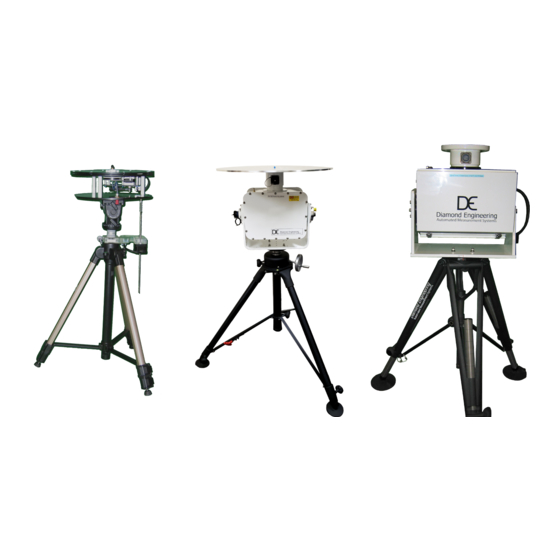
- Page 1 DAMS - Desktop Antenna Measurement System x000, x100, and x250 Series Users Manual & Setup Guide...
- Page 3 Congratulations on your purchase! Diamond Engineering’s Desktop Antenna Measurement System has been designed to aid in the testing and development of small to medium sized antennas. Using our state of the art software, this system enables you to make many different types of measurements with complete user-definable configuration settings.
- Page 4 This manual may not be reproduced without the express written consent of Diamond Engineering, nor any of the material contained herein. Diamond Engineering makes no representations of warranties or statements of fitness for any particular purpose. Furthermore, Diamond Engineering reserves the right to revise this publication or to make changes to the content herein free of obligation to notify any person of such version changes or updates.
-
Page 5: Table Of Contents
Table of Contents System Overview ................................3 Key Features ..............................................4 System Requirements ..........................................5 Supported Instruments .........................................5 Platform Controller Unit ........................................6 x000 Series Assembly, Installation & Configuration ....................7 Package Contents ............................................8 Assembly & Installation (Non-FSM) ....................................9 Attaching Optional Thrust Plate ......................................10 Assembly & Installation (with FSM-5) ....................................11 Attaching the Cables ..........................................12 Software Installation &... -
Page 7: System Overview
System Overview Key Features 5000, 6000 and 7000 Models... -
Page 8: Key Features
Key Features Light Weight Advanced Data Processing Features Platform is made of high quality, light weight Acrylic Designed for post measurement material for easy portability. processing you can perform a range of functions such as: Easy USB Connectivity • 3D visualization for all frequencies Unit easily connects to the computer using a and angles standard USB cable. -
Page 9: System Requirements
System Requirements • AMD / Intel (Core i5 or better is recommended) • 4 GB RAM (minimum) • 3 GB hard disk space • 1 available USB port • 1024 x 768 display resolution (minimum) • Keyboard and mouse • Compatible Network Analyzer or Power Meter/Spectrum Analyzer and Signal Generator •... -
Page 10: Platform Controller Unit
Platform Controller Unit Overview The USB Platform Controller unit is an extremely accurate microprocessor-based stepper controller. Movement signals are sent from the measurement PC to the controller unit where precision stepping sequences are generated. A development kit is included which enables you to write your own custom software to control the platform. -
Page 11: X000 Series Assembly, Installation & Configuration
x000 Series Assembly, Installation & Configuration DAMS x000 Series Instructions for assembly, installation and software configuration... -
Page 12: Package Contents
Package Contents Main Components Use the checklist below to verify all pieces are present and undamaged: 1. Positioner Platform 12. Two 10’ ultra-low-loss cables * 2. Tripod (SMA male-to-male) 3. Vertical assembly 13. Platform control cables 4. Vertical spacer 14. Digital inclinometer ** 5. -
Page 13: Assembly & Installation (Non-Fsm)
Assembly & Installation (Non-FSM) Introduction BEFORE YOU BEGIN: Unpack ALL items and ensure there are no damaged or missing parts. NOTE: The x000 Series is designed for non-FSM measurements using elevation motor. Vertical Assembly 1. Unfold tripod and extend the top half-way, then secure the height adjustment. (Fig. 1) 2. -
Page 14: Attaching Optional Thrust Plate
1. Ensure the azimuth setting on the 2. Place the tripod head in a horizontal tripod is unlocked. position and tighten the locking screw. 3. Align the colored tape on the platform 4. Loosen the tilt lock screw (see Img. 2) with the tape on the tripod head and allowing the platform to tilt. -
Page 15: Assembly & Installation (With Fsm-5)
Assembly & Installation (with FSM-5) IMPORTANT: For FSM-10 installation, please refer to the separate FSM-10 installation manual. Hardware Setup 1. Setup the tripod and extend the neck upwards about 14”. 2. Carefully thread the DAMS positioner onto the tripod. 3. Remove 2 of the 4 thrust plate screws to make room for the FSM mount. 4. -
Page 16: Attaching The Cables
Attaching the Cables Cable Checklist You should have received the following five cables with your DAMS System: Two (2) 10-foot RF Cables SMA/2.92mm/2.4mm/ or V 1.85mm cables (or optional 20- foot cables) One (1) USB cable (USB to Micro-USB) Two (2) 6-meter platform control cables Cable Connections NOTE: For FSM-5 connections, see photo on Page 11. -
Page 17: Software Installation & Configuration
Software Installation & Configuration Software Installation IMPORTANT: Administrator privileges are required to install software. 1. Place CD in CD-ROM or Insert Flash Drive, Navigate to drive and launch setup.exe 2. Click Next/OK through all setup screens. 3. Agilent Runtime and I/O libraries Setup will launch. Windows 10 Users: you will receive an error that the operating system is not supported - ignore this error. -
Page 18: Controller Setup & Usb Driver Installation
Controller Setup & USB Driver Installation Connecting Controller and Installing USB Drivers - (USB / USB-RS232) 1. Connect DAMS Platform Controller to computer via USB Cable. A window should appear indicating a new device has been found. IMPORTANT: When possible, always allow Windows to check for updated driver. 2. -
Page 19: Unit Calibration & Positioner Verification (Non-Fsm)
Unit Calibration & Positioner Verification (non-FSM) Calibrating Vertical Movement to Zero Degrees IMPORTANT: For the software to move the platform correctly on the vertical axis you must have the platform at zero degrees when starting the DAMS Software, or the platform must match the vertical position shown in the software before moving vertically. -
Page 20: X000 Series Plate Drawing
x000 Series Plate Drawing Plate Drawing Use the drawing below to help design fixtures to mount on your DAMS system. -
Page 21: X100 Series Assembly, Installation & Configuration
x100 Series Assembly, Installation & Configuration DAMS x100/x100B Series 100-pound capacity positioner with an extra heavy duty tripod and measuring capabilities frequencies of up to 40 GHz... -
Page 22: Package Contents
Package Contents Main Components Upon receiving your shipment of the DAMS x100 series, please verify you’ve received all items below while checking for any damages that may have occurred during the shipment process. Please contact us immediately if any missing or damaged items. 1. -
Page 23: Tripod & Positioner Assembly
Tripod & Positioner Assembly Assembly Steps CAUTION: Damaging any SMA connectors during assembly may result in faulty readings. BEFORE YOU BEGIN: Unpack all items and ensure there are no damaged or missing parts. 1. Lay the positioner on its side and attach the Tripod Adapter Plate to the bottom using the four Hex-Cap Screws and included hex wrenches. -
Page 24: Attaching The Cables
Attaching the Cables 1. Attach the control/power cables to the side of the positioner. (Fig. 1) 2. Connect the USB cable and white cable from control cable to USB interface, DO NOT connect to PC yet. (Fig. 2) 3. Connect power supply to power cable (Fig. 3) 4. -
Page 25: Using The Dams X100 Positioner
Using the DAMS x100 Positioner Assembly Steps NOTE: This section is related to the DAMS 6100 positioner ONLY. The 6100 positioner follows the same procedures as the original 5000, 6000, or 7000 positioners with exception to a few key items. The positioner is tracked using internal, absolute encoders at zero degrees so the positioner will always be in the same position. -
Page 26: X100 Legacy Positioner & Tripod Specifications
x100 Legacy Positioner & Tripod Specifications Movement Resolution: 0.1 degree both axis (6100/7100 models) 0.25 degree (5100 models) Horizontal / Azimuth: 0 to 360 degrees Vertical / Elevation: -90 to +90 degrees Horizontal / Az. torque: 50 ft-lbs. Vertical/Elev. Torque: 150 ft-lbs. -
Page 27: X100B Positioner & Tripod Specifications (2021 And Later)
x100B Positioner & Tripod Specifications (2021 and later) Movement Resolution: 0.1 degree both axis (all x100B models) Horizontal / Azimuth: 0 to 360 degrees Vertical / Elevation: -90 to +90 degrees Horizontal / Az. torque: 50 ft-lbs. Vertical/Elev. Torque: 90 ft-lbs. Drivetrain: Precision worm drive with roller bearings Weight Capacity:... -
Page 28: Positioner Troubleshooting
Positioner Troubleshooting Possible Problems & Solutions The DAMS x100 Series Positioner is a very robust and stable positioner. In the event that you believe you may have a problem with your positioner. Please check the items below. If you do not see your problem listed below or you are not able to get your problem resolved, please contact us and we will be happy to assist you with your problems. -
Page 29: Software Installation & Configuration
Software Installation & Configuration Software Installation IMPORTANT: Administrator privileges are required to install software. 1. Insert USB Drive into PC, Launch Setup.exe from flash drive 2. Click Next/OK through all setup screens. 3. Agilent Runtime and I/O libraries Setup may also launch. If so, install as well. 4. -
Page 30: Usb Driver Installation & Configuration
USB Driver Installation & Configuration Installing the USB Driver IMPORTANT: If you ordered a pre-configured PC, you do NOT need to perform any of these steps unless you are re-installing the system. Antenna Measurement Studio should be installed before performing the steps below. 1. -
Page 31: Unit Calibration & Positioner Verification
Unit Calibration & Positioner Verification Verifying Positioner Connectivity and Operation These steps will assist you with verifying the x100 Series positioner’s operation with the DAMS software. All previous steps for installing and configuring the software and connecting cables should be completed before performing the following steps. Step 1 Ensure all cables are connected and power supply is plugged in. -
Page 32: X100B Plate And Hub Drawings
2.475 4.000 7.000 10.000 Part: x100B DUT mounting plate Material: 6061 Aluminum .250" stock Tolerance: .005" std Finishing: debur + black anodize Units: Inches Drawing Date: 6/21/2021 .250 Diamond Engineering Inc. support@diamondeng.net (530)626-3857 X100B Hub Drawing x100 Installation & Configuration... -
Page 33: X250 Series Assembly, Installation & Configuration
x250 Series Assembly, Installation & Configuration DAMS x250 Series 250-pound capacity positioner with an extra heavy duty tripod and measuring capabilities frequencies of up to 40 GHz... -
Page 34: Package Contents
Package Contents Main Components Upon receiving your shipment of the DAMS x100 series, please verify you’ve received all items below while checking for any damages that may have occurred during the shipment process. Please contact us immediately if any missing or damaged items. 1. -
Page 35: Tripod & Positioner Assembly
Tripod & Positioner Assembly Assembly Steps CAUTION: Damaging any SMA connectors during assembly may result in faulty readings. BEFORE YOU BEGIN: Unpack all items and ensure there are no damaged or missing parts. 1. Unfold tripod, Remove Threaded ring from adapter plate (Fig. 1) 2. -
Page 36: Attaching The Cables
Attaching the Cables 1. Attach the power and control cables to the side of the positioner. (Fig. 1) 2. Connect the USB adapter to the Serial End of the control cable (Fig. 2) 3. Connect Power cable to the power supply (Fig. 3) 4. -
Page 37: Using The X250 Positioner
Using the x250 Positioner Operation Tips NOTE: This section is related to the x250 positioner ONLY. The x250 positioner follows the same procedures as the original 5000, 6000, or 7000 positioners with exception to a few key items: The units positioner is tracked using internal, absolute encoders at zero degrees so the positioner will always be in the same position, no zeroing is required Before making any measurements, ensure the positioner is at 0 degrees azimuth and 0 degrees elevation by using the... -
Page 38: X250 Positioner & Tripod Specifications
x250 Positioner & Tripod Specifications Movement Resolution: 0.01 degree both axis Horizontal / Azimuth: 0 to 360 degrees Vertical / Elevation: -90 to +90 degrees Vertical/Elev. Torque: 500 ft-lbs. Drivetrain: Precision worm drive with roller bearings Weight Capacity: 250 lbs. Electrical Volts: 48 VDC... -
Page 39: X250 Thrust Plate / Mounting Plate Drawing
x250 Thrust Plate / Mounting Plate Drawing Units: Inches x250 Installation & Configuration... -
Page 40: Positioner Troubleshooting
Positioner Troubleshooting Possible Problems & Solutions The DAMS x100 Series Positioner is very robust and stable. If you believe you may have a problem, please check the items below. If you do not see your problem listed below or you are not able to get your problem resolved, please contact us and we will be happy to assist you. -
Page 41: Software Installation & Configuration
Software Installation & Configuration Software Installation IMPORTANT: Administrator privileges are required to install software. 1. Place CD in CD-ROM. Setup should start automatically. If setup does not, click: Start Menu → Run → Browse, and locate SETUP.EXE in the CD-ROM. 2. -
Page 42: Usb Driver Installation & Configuration
USB Driver Installation & Configuration Installing the USB Driver IMPORTANT: If you ordered a pre-configured PC, you do NOT need to perform any of these steps unless you are re-installing the system. Antenna Measurement Studio should be installed before performing the steps below. 1. -
Page 43: Unit Calibration & Positioner Verification
Unit Calibration & Positioner Verification Verifying Positioner Connectivity and Operation These steps will assist you with verifying the x250 Series positioner’s operation with the DAMS software. All previous steps for installing and configuring the software and connecting cables should be completed before performing the following steps. Step 1 Ensure all cables are connected and power supply is plugged in. - Page 44 x250 Installation & Configuration...
-
Page 45: Troubleshooting & Service
Troubleshooting & Service General Problem Solving & Maintenance Info... -
Page 46: General System Troubleshooting
General System Troubleshooting Problem Possible Causes Solutions Power supply not connected Check the above items and if all is correct, please Power supply light correctly, Power Switch is not contact us for service. on but controller is turned ON? not on USB cable not connected? Check all connections and reboot. -
Page 47: Warranty, Replacement Parts & Contact Information
Warranty, Replacement Parts & Contact Information Warranty Information Diamond Engineering’s Antenna Measurement Systems are guaranteed from one to three years on parts and labor from the time it was received by you. If there is an issue with the product please send us a picture or write a very detailed description of the problem.
Need help?
Do you have a question about the DAMS 000 Series and is the answer not in the manual?
Questions and answers