Advertisement
Quick Links
Owner's Instruction and Operation Manual
Model Number:
DVAG11-DF, DVAG17-DF,
DVAG25-DF
Report Number:
Certified to ANSI STD Z21.86-2016 (R2021)
and Certified to CSA STD 2.32-2016 (R2021)
* All Pictures In This Manual Are For Illustrative Purposes Only. Actual Product May Vary.
Save These Instructions In A Safe Place For Future Reference.
WARNING: If the information in these instructions is not followed exactly, a fire or explosion may result
- Do not store or use gasoline or other flammable vapors and liquids in the vicinity of this or any other
appliance.
- WHAT TO DO IF YOU SMELL GAS:
•
Do not try to light any appliance.
•
Do not touch any electrical switch; do not use any phone in your building.
•
Immediately call your gas supplier from a neighbor's phone. Follow the gas supplier's instructions.
•
If you cannot reach your gas supplier, call the fire department.
- Installation and service must be performed by a qualified installer, service agency or the gas supplier.
* Installation and service must be performed by a qualified installer, service agency or the gas supplier *
Please read this manual BEFORE
installing and operating this unit.
INSTALLER: Leave this manual with the appliance.
CONSUMER: Retain this manual for future reference.
THIS MANUAL IS SUBJECT TO CHANGE WITHOUT NOTICE.
© 2023 United States Stove Company, 227 Industrial Park Rd., South Pittsburg, TN 37380
R
causing property damage, personal injury or loss of life.
CALIFORNIA PROPOSITION 65 WARNING:
This product can expose you to chemicals including carbon
monoxide, which is known to the State of California to cause
cancer, birth defects, and/or other reproductive harm. For
more information, go to
854081-4203M
www.P65warnings.ca.gov
Ph. 800-750-2723
Advertisement

Subscribe to Our Youtube Channel
Related Manuals for Ashley DVAG11-DF


Summary of Contents for Ashley DVAG11-DF
- Page 1 Owner’s Instruction and Operation Manual Model Number: DVAG11-DF, DVAG17-DF, DVAG25-DF Report Number: Certified to ANSI STD Z21.86-2016 (R2021) and Certified to CSA STD 2.32-2016 (R2021) * All Pictures In This Manual Are For Illustrative Purposes Only. Actual Product May Vary.
-
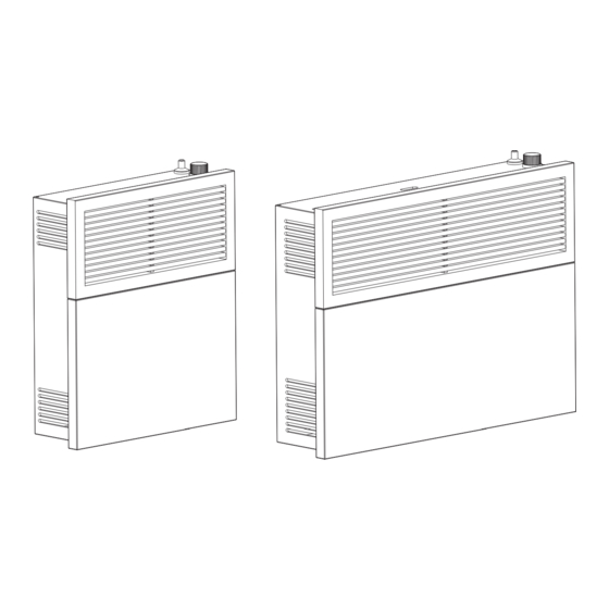
Page 2: Figure 1
DIMENSIONS MODEL: DVAG11-DF Height 20 (508 mm) Width 27.36 (695 mm) Depth 6.61 (168 mm) Weight lbs. (kg.) 43 (19.5 kg) Type of Burner Atmospheric 20" (508 mm) # of Burners Ignition Piezo-electric ignitor Standard Heating 570 (52.9 m Space Square Feet/(m MODEL: DVAG25-DF 17.36"... - Page 3 INSTALLATION CHECKLIST Your Gas Stove should be installed by a qualified installer only. An NFI qualified Installer can be found at www.nficertified.org/public/find-an-nfi-pro/ INSTALLER CHECK LIST This Checklist is to be completed in full by the qualified person who installs this unit. Keep this page for future reference.
- Page 4 MASSACHUSETTS RESIDENTS REQUIREMENTS FOR THE SIGNAGE COMMONWEALTH OF A metal or plastic identification plate shall be MASSACHUSETTS permanently mounted to the exterior of the building at a minimum of eight (8) feet above The following requirements reference various grade directly in line with the exhaust vent terminal Massachusetts and national codes not contained for the horizontally vented gas fueled heating the in this manual.
- Page 5 MASSACHUSETTS RESIDENTS referenced “special venting systems” A copy of all installation instructions for all Product instructions shall be included with the appliance or Approved side wall horizontally vented gas fueled equipment installation instructions and; equipment, all venting instructions, all parts lists for venting instructions, and/or all venting design The “special venting systems”...
- Page 6 Valve Type (kW) Manifold inch W.C. (mm. W.C.) W.C. (mm. W.C.) W.C. (mm. W.C.) DVAG11-DF (LP) DVAG11-DF (NG) DVAG17-DF (LP) DVAG17-DF (NG) DVAG25-DF (LP) DVAG25-DF (NG) **NOTE: Minimum Gas Inlet Pressure for purpose of input adjustment. The efficiency rating of the appliance is a product thermal efficiency rating determined under continuous operating conditions and was determined independently of any installed system.
- Page 7 INSTALLATION IN S ID T A IL E R D E C O R N F IX E D C L O S A B LE O P E R F IX E D C L O S A B LE O P E R AIR SUPPLY INLET VENT TERMINAL...
- Page 8 INSTALLATION INSTALLING THE APPLIANCE IMPORTANT: Separate the hanging bracket from the appliance INSTALLATION REPAIR SHOULD by removing two screws on the top and two nuts at DONE BY A QUALIFIED SERVICE PERSON. the bottom. APPLIANCE SHOULD INSPECTED BEFORE USE AND AT LEAST ANNUALLY BY A QUALIFIED SERVICE PERSON.
-
Page 9: Insert The Two Provided Rubber Grommets (V)
Height “C” is the minimum Check to see if the bracket is level. After leveling recommended. the hanging bracket, mark the four holes. TABLE 1 MODEL DVAG11-DF 20-7/32” (514 mm) 11-1/4” X 11-1/4” DVAG17-DF 20” (508 mm) (286 x 286 mm) square hole DVAG25-DF 25-7/16”... -
Page 10: Important: The Four 1/4" Spacer Washers (Iv)
(fold along the perforated lines and break off when installing in a 2 X 4 wall). Align the holes on the DVAG11-DF heat shield with the holes on the mounting 11-1/4” x 11-1/4”... -
Page 11: Table Of Contents
INSTALLATION trim the hole you cut to ensure the bracket is level when installed. After leveling the hanging bracket, mark the 4 holes as shown. Figure 17 Figure 20 6. Remove the hanging bracket and drill the four holes using a 3/32” drill bit. Place the hanging bracket and attach it Figure 18 with four screws (ii) and four washers (iii). -
Page 12: Figure 22
INSTALLATION MOUNTING THE HEATER ONTO THE HANGING BRACKET Place the heater on the hanging bracket and RATING PLATE, secure with two small screws (vi). OPERATION INSTRUCTIONS, AND SAFETY PLATE Figure 24 INSTALLING THE VENTING SYSTEM These models of wall furnaces are designed for direct venting through a wall. - Page 13 INSTALLATION The venting system consists of: Measure thickness of the wall as shown in figure 26. If any of the following are long trim them Vent Cap according to thickness of the wall, (see table 3): Vent Pipe • (B) vent pipe Vent-Air Intake Pipe •...
- Page 14 INSTALLATION The outdoor mounting plate (F) and the silicon- rubber ring (G) should be installed between REQUIRED: the vent cap (A) and the exterior wall. Note: For Upward slope of additional security the outdoor mounting plate 1/4” per foot of Flush with (F) can be attached to the outside of the wall venting to the...
- Page 15 INSTALLATION 2. Place the thermostat sensor under the right CAUTION: bottom of the bracket and attach it with THE KNOB TO THE GAS SELECTION SHALL the provided screw (i) that fixes the medium NOT BE ACCESSED OR ADJUSTED WHILE THE appliance to the bracket as shown.
- Page 16 INSTALLATION 4. The gas supply system must include a manual WARNING: shut off valve and connection in the line, so the • FOR L.P. GAS, USE PRESSURE REGULATED heater can be disconnected for servicing. (See GAS SUPPLY. DO NOT DIRECTLY CONNECT Figure 32).
- Page 17 OPERATION WARNING: IF YOU DO NOT FOLLOW THESE INSTRUCTIONS EXACTLY, A FIRE EXPLOSION MAY RESULT CAUSING PROPERTY DAMAGE, PERSONAL INJURY OR LOSS OF LIFE. damage, personal injury or loss of life. LIGHTING INSTRUCTIONS 1. STOP! Read the safety information on the attached plate. Pliot Burner 2.
- Page 18 OPERATION IMPORTANT: • DO NOT DRY CLOTHES OVER THE HEATER. • DO NOT SPRAY ANY AEROSOL NEAR THE HEATER WHEN FUNCTIONING. DO NOT STORE THESE ELEMENTS NEAR THE APPLIANCE. • DO NOT TOUCH GRILL TO AVOID BURNS. • AVOID BLOCKING AIR INLET AND HOT AIR OUTLET. •...
- Page 19 HOW TO ORDER REPAIR PARTS For Parts Assistance Call: 800-750-2723 Ext 5051 or Email: parts@usstove.com The information in this owner’s manual is specific to your unit. When ordering replacement parts the information in this manual will help to ensure the correct items are ordered. Before contacting customer service write down the model number and the serial number of this unit.
- Page 20 TROUBLESHOOTING WARNING: TURN OFF HEATER AND LET COOL BEFORE SERVICING. ONLY A QUALIFIED SERVICE PERSON SHOULD SERVICE AND REPAIR HEATER. PROBLEM POSSIBLE CAUSE REMEDY Ignitor electrode broken. Replace ignitor electrode. Ignitor electrode not connected Reconnect ignitor cable. to ignitor cable. When ignitor button is pressed, there is no Free ignitor cable if pinched by any metal...
- Page 21 TROUBLESHOOTING PROBLEM POSSIBLE CAUSE REMEDY Clean burner orifice or replace burner Burner orifice is clogged. Burner does not light orifice. after pilot is lit. Inlet gas pressure is too low. Contact local Gas Company. It is normal for the new wall furnace to give some odor the first time it is burned.
- Page 22 REPLACEMENT PARTS © 2023 United States Stove Company...
- Page 23 REPLACEMENT PARTS Part # Description Model 81311 DVAG11-DF DVAG11-DF, 81312 Burner DVAG17-DF 81347 DVAG17-DF, 81313 DVAG25-DF DVAG25-DF Pilot DVAG11-DF, Assembly 81345 DVAG11-DF, Burner Connection DVAG17-DF 81303 DVAG17-DF, Tube 81346 DVAG25-DF DVAG25-DF 893236 “Vent Pipe Kit DVAG11-DF 81342 DVAG11-DF (Includes inner/...
- Page 24 SERVICE RECORD It is recommended that your heating system is serviced regularly and that the appropriate Service Interval Record is completed. SERVICE PROVIDER Before completing the appropriate Service Record below, please ensure you have carried out the service as described in the manufacturer’s instructions. Always use the manufacturer's specified spare part when replacement is necessary.
Need help?
Do you have a question about the DVAG11-DF and is the answer not in the manual?
Questions and answers
where can I get a pilot assembly for an ashley direct vent dvag11L
The pilot assembly for the Ashley Direct Vent DVAG11-DF is listed under part number 893041 in the parts documentation.
This answer is automatically generated