Table of Contents
Advertisement
Quick Links
©2024
burster
praezisionsmesstechnik gmbh & co kg
All rights reserved
Valid from: 31.01.2024
OPERATION MANUAL
USB Sensor Interface
Model 9206
Manufacturer:
burster praezisionsmesstechnik gmbh & co kg
Talstraße 1 – 5
76593 Gernsbach
Germany
Tel.:
Fax.:
E-Mail
P.O.Box 1432
76587 Gernsbach
Germany
(+49) 07224 / 6450
(+49) 07224 / 64588
info@burster.com
www.burster.com
4505-BA9206EN-5699-021526
Advertisement
Table of Contents

Related Manuals for Burster 9206


Summary of Contents for Burster 9206
- Page 1 OPERATION MANUAL USB Sensor Interface Model 9206 ©2024 burster Manufacturer: praezisionsmesstechnik gmbh & co kg burster praezisionsmesstechnik gmbh & co kg All rights reserved Talstraße 1 – 5 P.O.Box 1432 76593 Gernsbach 76587 Gernsbach Germany Germany Valid from: 31.01.2024 Tel.: (+49) 07224 / 6450 Fax.:...
- Page 2 "product") are the results of targeted development and meticulous research. As of the date of delivery, burster provides a warranty for the proper condition and functioning of these products covering material and production defects for the period specified in the warranty document accompanying the product.
- Page 3 USB Sensor Interface Model 9206 Page 3...
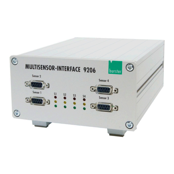
- Page 4 USB Sensor Interface Model 9206 1 channel In Line (IP67) USB Multisensor-Interface desktop unit (IP20) Page 4...
- Page 5 USB Sensor Interface Model 9206 Warning! The following instructions must be followed to prevent electric shock and injuries: Follow all equipment safety procedures. Only use the device outside from explosive areas. Only use the device when it is undamaged.
-
Page 6: Table Of Contents
Model 9206-V0xxx / 9206-V2xxx ............. 19 Preparation for use ......................20 System requirements .................... 20 Software installation ....................20 Driver installation ....................26 Software licensing for 9206-P100/P200 multi-channel operation ......35 Initial operation ......................... 36 Internal signal processing..................36 Page 6... - Page 7 USB Sensor Interface Model 9206 Supply voltage ....................... 36 Adjustment using PC software 9206-P001/P100/P200 ......... 36 Device list ......................37 Device settings ...................... 37 Adjustment of strain gauge sensors ................41 General information ....................41 Types of connection ....................42 Adjustment using a physical variable by the teach-in method .......
- Page 8 USB Sensor Interface Model 9206 8.11 Archive viewer ....................... 70 8.12 Exporting reports to Excel ..................71 8.12.1 Print reports ..................... 72 Maintenance and customer service ................74 Maintenance ......................74 Cleaning ........................ 74 Disposal ........................ 74 10. Technical data ........................75 11.
-
Page 9: Introduction
USB Sensor Interface Model 9206 Introduction The model 9206 USB Sensor Interface is intended for the acquisition and processing of sensor signals. The model 9206 USB Sensor Interface is a user-configurable single-channel device, or optionally a multi-channel device housed in a desktop unit. The device is configured via the USB port. The model 9206 USB Sensor Interface is ideally suited to measuring mechanical variables such as force, torque, pressure, acceleration, displacement and angle. -
Page 10: Normal Use
The model 9206 USB Sensor Interface is designed only for measurement functions in industry and test laboratories, and for reference measurements, but is not intended for use in medical applications or where people are at risk. -
Page 11: Factory Warranty
9206 USB Sensor Interface. Important note Note that the model 9206 USB Sensor Interface must be used in accordance with the instructions, technical data and conditions of use listed in this manual. If handled improperly or used incorrectly, one cannot rule out the possibility of faults, incorrect measurements, effects on or from other equipment and installations or potential risks to life and property. -
Page 12: Preparation
The packaging should be retained for examination by a representative of the manufacturer and/or the delivery company. The model 9206 USB Sensor Interface must be shipped only in its original packaging provided by us or in a container capable of providing an equivalent degree of protection. -
Page 13: Opening The 9206 Tubular Housing
Before opening the tubular housing always undo both PG cable glands. Before opening or closing the tubular housing, isolate the 9206 from the power supply. For the in-line 9206 model, all controls and connections are located inside the tubular housing. PG cable gland Finely knurled end-fitting... -
Page 14: Degree Of Protection
Once the housing is unscrewed from the end fittings, the circuit board is exposed. Degree of protection The In Line unit of the model 9206 USB Sensor Interface has IP67 degree of protection. The module is therefore protected from the effect of temporary immersion in water and accessing dangerous components using a wire of diameter ≥... -
Page 15: Connection Via Screw-Terminals
USB Sensor Interface Model 9206 Connection via screw-terminals The screw terminals located on the circuit board of the 9206 USB Sensor Interface are listed in the figure below. 12-pin plug 9-pin plug Terminal block in Meaning Pt100 9941 9900-V209 tubular housing... -
Page 16: Connecting Sensors Via Plug-In Connectors
USB Sensor Interface Model 9206 Connecting sensors via plug-in connectors 2.8.1 Connecting a Pt100 sensor 12-pin plug 9-pin plug 9941 9900-V209 Page 16... -
Page 17: Connecting A Strain Gauge Sensor Without Sensor Leads
USB Sensor Interface Model 9206 2.8.2 Connecting a strain gauge sensor without sensor leads 12-pin plug 9-pin plug 9941 9900-V209 Strain gauge housing housing 2.8.3 Connecting a strain gauge sensor fitted with sensor leads 12-pin plug 9-pin plug 9941 9900-V209... -
Page 18: Connecting Sensors Having A Normalized Signal Output
USB Sensor Interface Model 9206 2.8.4 Connecting sensors having a normalized signal output 12-pin plug 9-pin plug 9941 9900-V209 Sensor with standard signal output ± 10 V housing housing Note: When connecting sensors that require a transmitter excitation voltage, the sensor lines (pins B and D or pins 4 and 2) must not be connected! A bridge between the sensor line and the supply voltage could damage the measuring amplifier. -
Page 19: Indicating Elements
USB Sensor Interface Model 9206 Indicating elements 2.9.1 Model 9206-V3xxxx There is an LED light for every measurement channel on the front panel. The following table describes the meaning of the different colours: Colour Description Error Yellow Overdrive Green Standard operation... -
Page 20: Preparation For Use
USB Sensor Interface Model 9206 Preparation for use System requirements Operating system: Windows 2003, Windows XP, Windows 7, Windows 8 Processor: min. Pentium 1200 MHz, recommended Pentium 2,0 GHz Graphics: min. VGA 800 x 600, min. 256 colors Memory: min. 256 MB RAM (Win XP), min. 512 MB (Win 2003, Win 7) Hard disk: approx. - Page 21 USB Sensor Interface Model 9206 Diagram 6: Installing DV, startup screen Double-click to choose a language and start installation: If Microsoft .NET Framework 4.0 is not already installed on the PC, it is installed automatically. Diagram 7: Installing DV, welcome Click on button “Next”.
- Page 22 USB Sensor Interface Model 9206 Diagram 8: Installing DV, license agreement Accept the license agreement then confirm with “Next”. The installation will terminate if you don´t accept the license agreement. This window lists all relevant information. This information is also held in the file “readme.txt”, if you need to refer to it again later.
- Page 23 USB Sensor Interface Model 9206 Diagram 9: Installing DV, user information Insert the username and the company or organization. Specify to whom the application will be installed. Confirm with “Next”. Page 23...
- Page 24 USB Sensor Interface Model 9206 Diagram 10: Installing DV, installation path Make a note of the installation path. The sensor driver is located in a subdirectory. You will need to know this path later when you install the driver.
- Page 25 USB Sensor Interface Model 9206 Click on button “Install”. Diagram 11: Installing DV, installation running Page 25...
-
Page 26: Driver Installation
It is a Windows requirement that you must have Administrator rights to install drivers. Please contact your system administrator if you do not have these rights. Plug the model 9206 USB Sensor Interface into a spare USB port of your PC. ... - Page 27 USB Sensor Interface Model 9206 In Device Manager, select the sensor´s interface. Diagram 13: Installing driver software, Device Manager Select “Update Driver Software…“ Diagram 14: Installing driver software, select type of search Page 27...
- Page 28 USB Sensor Interface Model 9206 Select “Browse my computer for driver software“ Diagram 15: Installing driver software, search path Specify the path to the driver installation files. After installing the DigiVision configuration and analysis software, the driver installation files are located in the folder you specified when installing DigiVision.
- Page 29 USB Sensor Interface Model 9206 Diagram 16: Installing driver software, select folder with driver Confirm with “OK“. Diagram 17: Installing driver software, confirm path Page 29...
- Page 30 USB Sensor Interface Model 9206 Confirm with “Next”. Diagram 18: Installing driver software, installation successful The operating system now confirms that the driver for the model 9206 USB Sensor Interface has been installed successfully. Page 30...
- Page 31 USB Sensor Interface Model 9206 The installation procedure for the virtual COM port then starts. Open the Device Manager again. (Go to Start Control Panel Hardware Device Manager). Diagram 19: Port installation, Device Manager Right-click on USB Serial Port and select Update Driver Software…...
- Page 32 USB Sensor Interface Model 9206 Diagram 21: Installing port driver, install driver, select type of search Select “Browse my computer for driver software“. Diagram 22: Installing port driver, search path Page 32...
- Page 33 USB Sensor Interface Model 9206 Enter the same file path you specified in the first part of the installation procedure. Confirm with “Next”. Diagram 23: Installing port driver, confirm path Confirm with “Next”. Page 33...
- Page 34 USB Sensor Interface Model 9206 The operating system confirms the installation of the virtual COM port. Diagram 24: Installing port driver, installation successful Click on “Finish” to close the window. Page 34...
-
Page 35: Software Licensing For 9206-P100/P200 Multi-Channel Operation
The multi-channel version, which you can always order subsequently, provides a graphical display facility for up to eight model 9206 USB Sensor Interfaces in parallel. This version also releases the full measurement rate capability of 2500 measurements/second. To enable the multi-channel version for the 9206 equipment series in DigiVision, follow the steps below:... -
Page 36: Initial Operation
The number of values used to find the average can be set in the range 1 to 256. Supply voltage The model 9206 USB Sensor Interface takes its supply from the USB port of the connected PC or USB hub. In the multi-channel version, power is supplied from an internal power supply unit included in the package. -
Page 37: Device List
Device list You can use the device finder facility to get the computer to detect automatically the model 9206 USB Sensor Interfaces that are connected. All detected devices are displayed. To display all connected devices: After opening the DigiVision software, click on the "Find" button. - Page 38 The calibration date is updated with the date and time whenever new data is transferred to the model 9206 USB Sensor Interface. Software version Shows the current software version in the model 9206 USB Sensor Interface. Serial number This field displays the serial number of the model 9206 USB Sensor Interface currently connected. Page 38...
- Page 39 USB Sensor Interface Model 9206 Diagram 28: DV, device settings Measurement input In order to be able to use 100 % of the measurement range of the connected sensor, the selected input range must be the ≥ the sensor sensitivity.
- Page 40 USB Sensor Interface Model 9206 Sensor excitation voltage The following sensor excitation voltages are possible: 2.5 V • • The correct value for the sensor excitation voltage is listed on the datasheet or the test certificate. Page 40...
-
Page 41: Adjustment Of Strain Gauge Sensors
USB Sensor Interface Model 9206 Adjustment of strain gauge sensors General information The model 9206 USB Sensor Interface can be calibrated by a choice of methods. Adjustment using a physical variable • Adjustment by entering data from the sensor test certificate •... -
Page 42: Types Of Connection
USB Sensor Interface Model 9206 Types of connection Strain gauge connection method + excitation + sensor line + signal - signal - sensor line - excitation shield Diagram 30: Strain gauge connection method Note: A measuring chain contains a number of components, each contributing to the overall measurement accuracy of the test setup. -
Page 43: Adjustment Using A Physical Variable By The Teach-In Method
Adjustment using a physical variable by the teach-in method This method involves a two-stage online teach-in of sensor data to the model 9206 USB Sensor Interface, where two teach-in states are applied sequentially. The first state is the zero point under no load (lower scale value), and the second state is the upper limit (upper scale value). - Page 44 USB Sensor Interface Model 9206 Perform the teach-in as follows: Remove any load from the load cell to set the zero point, F = 0 N (lower scale value). Now enter the lower scale value of the sensor measurement range.
- Page 45 USB Sensor Interface Model 9206 Diagram 31: Sensor characteristic curve You now need to "Transfer" these sensor parameters to the sensor interface. You can also save them in a file. Diagram 32: DV, device settings 9206 Page 45...
-
Page 46: Adjustment Using The Sensor Test And Calibration Certificate
Adjustment using the sensor test and calibration certificate This method involves using the test and calibration certificate to enter the sensor data directly in the model 9206 USB Sensor Interface. All necessary adjustment data can be found from the sensor test certificate. - Page 47 The method of “Adjustment using the sensor test and calibration certificate” is a two-point calibration of the sensor data for the model 9206 USB Sensor Interface, with two points being entered one after the other. The first point is the zero point without load (lower scale value), and the second point is the upper limit (upper scale value).
- Page 48 USB Sensor Interface Model 9206 Diagram 34: DV, device settings 9206 Page 48...
-
Page 49: Adjustment Of Potentiometric Displacement Sensors
USB Sensor Interface Model 9206 Adjustment of potentiometric displacement sensors Adjustment is necessary in order to define the relationship between the electrical signals measured by the connected sensors and the measured values to be displayed. A two-point calibration procedure is used here. Normally the sensors have a test and calibration certificate containing details of the electrical signals. -
Page 50: Connection
USB Sensor Interface Model 9206 Connection The connector-pin numbering for the potentiometric displacement sensor is given in the test and calibration certificate. Diagram 36: Physical connection Diagram 37: Circuit diagram Page 50... -
Page 51: Adjustment Of A Potentiometer By The Teach-In Method
USB Sensor Interface Model 9206 Adjustment of a potentiometer by the teach-in method This method involves a two-stage online teach-in of sensor data to the model 9206 USB Sensor Interface, where two teach-in states are applied sequentially. The first state is the lower scale value, and the second state is the upper scale value. - Page 52 USB Sensor Interface Model 9206 Diagram 38: Sensor characteristic curve Diagram 39: DV, device settings 9206 Page 52...
-
Page 53: Sensor Excitation Voltage
To enable practical measurements, choose the terminal with the 5 V excitation voltage. The maximum measurement signal output from potentiometers to the model 9206 USB Sensor Interface is always the excitation voltage. Connection The connector-pin numbering for the potentiometric displacement sensor is given in the test and calibration certificate. -
Page 54: Adjustment Of Transmitters Or Sensors Having A Standard Signal Output
USB Sensor Interface Model 9206 Adjustment of transmitters or sensors having a standard signal output Adjustment is necessary in order to define the relationship between the electrical signals measured by the connected sensors and the measured values to be displayed. A two-point calibration procedure is used here. -
Page 55: Connection
Diagram 44: Circuit diagram Sensor excitation voltage The model 9206 USB Sensor Interface provides excitation voltages for sensors and transmitters. Please note: A maximum current of 80 mA Bei der Versorgungsspannung von 12 V darf maximal ein Strom von 80 mA fließen. -
Page 56: Adjustment Of A Transmitter Having A Voltage Output Using The Teach-In Method
Then click in the left-hand menu bar on "Import parameters from device (online)" When you do this, you import the sensor parameters saved in the model 9206 USB Sensor Interface into the configuration software. Now you can perform the teach-in to obtain the new sensor parameters. - Page 57 USB Sensor Interface Model 9206 Diagram 45: Sensor characteristic curve Diagram 46: DV, device settings 9206 Page 57...
-
Page 58: Adjustment Using The Sensor Test Certificate
USB Sensor Interface Model 9206 Adjustment using the sensor test certificate Diagram 47: DV, device settings 9206 About the values: These values are adopted directly from the test and calibration certificate. Origin of slope. In this case this equals 0 (zero) ... -
Page 59: Adjustment Of Pt100 Sensors
Adjustment of Pt100 sensors The 9206 USB Sensor Interface includes a Pt100 linearization facility using standard values for uncalibrated sensors or specific values for calibrated sensors. Manual input of specific coefficients of a Pt100s sensor for linearization in accordance with ITS 90 / EN 60751 R = 100 Ohms and an Alpha value of 3.851:... -
Page 60: Measurement Mode
USB Sensor Interface Model 9206 Measurement mode Device detection Device detection is possible in the licensed version of the software. Depending on the installation situation, DigiVision may already recognize the sensor or it may need to find it. If the sensor is not displayed, run the device detection process. -
Page 61: Operation
The MIN and MAX values are also shown with the curve. The measurement channels can be shown and hidden individually. Diagram 51: DV, standard version 9206-P001 The standard version of 9206-P001 is supplied with the sensor. Page 61... -
Page 62: 8.3.2 Tare Function
USB Sensor Interface Model 9206 Diagram 52: DV, licensed version 9206-P100 The paid version of 9206-P100 can display up to 16 measurement channels. 8.3.2 Tare function To zero the display and the measurement curve: Click on the Tare button in the Measurement window. -
Page 63: Options
Refer to the software manual or the Online Help facility for further details of the DigiVision software. When the DigiVision software is run for the first time, in the free 9206-P001 version, a USB Sensor Interface is assigned measurement channel 1. In the 9206-P100/P200 version, channels 1 to 32 are assigned. -
Page 64: Channel Settings
USB Sensor Interface Model 9206 Channel settings In the Channel settings window you can set the parameters for the respective measurement channel. Diagram 54: DV, channel settings The default setting is to adopt the parameters from the device, although you can also make manual changes to any parameter. -
Page 65: Selecting The Measurement Rate
Measurement rates between 0.1 and 20 measurements per second are possible here. • SOPM – Speed Optimized Polling Mode With the 9206-P001, up to 200 measurements per second are possible, with the 9206-P100/-P200, up to 1200 measurements per second are possible. -
Page 66: Trigger
USB Sensor Interface Model 9206 Trigger Measurement can also be stopped using a trigger with a suitable stop condition. Diagram 56: DV, Trigger Repeat measurement after time interval This setting specifies a time interval after which a repeat measurement takes place following the end of a measurement process. -
Page 67: Documentation
USB Sensor Interface Model 9206 Documentation Diagram 57: DV, documentation Various documentation settings are available here. Page 67... -
Page 68: Measurement Reports
USB Sensor Interface Model 9206 8.10 Measurement reports Note: If you wish to save the raw data for recording the measurements, before starting the measurement you must check the box “Save raw-data measurement files” under “Preferences > Data storage”. 8.10.1 Measurement report finder The DigiVision software has a convenient archiving facility for measurement reports. - Page 69 USB Sensor Interface Model 9206 Reports are classified under two different types here: Measurement report • Measurement report for each separate device involved in the series of measurements. Group report • Report for the series of measurements. Each measurement report involved in the series of measurements is held here.
-
Page 70: Archive Viewer
USB Sensor Interface Model 9206 8.11 Archive viewer Once you have selected the measurement reports from the Report Finder window, the Archive viewer opens. This gives you detailed information on your measurement. The Archive viewer is also the management center for viewing and editing reports. -
Page 71: Exporting Reports To Excel
USB Sensor Interface Model 9206 8.12 Exporting reports to Excel Note: To export measurement reports into XLS format, it is not necessary for Microsoft Excel or an equivalent program to be installed. Once you have selected the reports you require in the Archive viewer, you can export them into an XLS file by clicking on the "Export"... -
Page 72: 8.12.1 Print Reports
USB Sensor Interface Model 9206 8.12.1 Print reports Once you have selected the reports you require in the Archive viewer, you can print the measurement reports by clicking on the "Print" button. Follow the steps below: Select the required report by left-clicking on it. - Page 73 USB Sensor Interface Model 9206 The Output settings window opens. Diagram 62: DV reports, print options Now specify how you want the data to be output. You have the option to choose a printer, print preview or output as a PDF document.
-
Page 74: Maintenance And Customer Service
USB Sensor Interface Model 9206 Maintenance and customer service Maintenance The model 9206 USB Sensor Interface requires no maintenance by the user. Any repairs that may be needed must be performed only at the manufacturer's premises. Cleaning Do not use any cleaning agents that contain organic solvents or concentrated inorganic constituents. -
Page 75: Technical Data
USB Sensor Interface Model 9206 Technical data Only values that include tolerances or limits are data covered by the warranty. Values that do not include tolerances are provided for information and do not come under the warranty. Input signal Strain gage Bridge resistor (full-bridge): 350 Ω... -
Page 76: Accessories And Options
Model 92-ABG Calibration of a complete measuring chain This service includes calibration of the model 9206 USB Sensor Interface for the sensor ordered with it or for the sensor data provided by the customer (e.g. rated output or sensor test certificate).
Need help?
Do you have a question about the 9206 and is the answer not in the manual?
Questions and answers