Advertisement
OHNIYOU
Model: GLX054
USE AND CARE GUIDE
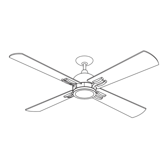
40-INCH CEILING FAN
THANK YOU
We appreciate the trust and confidence you have purchased this ceiling fan. We strive to continually create quality products designed to
enhance your home. Visit us online to see our full line of products available for your home !
Advertisement

Related Manuals for OHNIYOU GLX054


Summary of Contents for OHNIYOU GLX054
- Page 1 OHNIYOU Model: GLX054 USE AND CARE GUIDE 40-INCH CEILING FAN THANK YOU We appreciate the trust and confidence you have purchased this ceiling fan. We strive to continually create quality products designed to enhance your home. Visit us online to see our full line of products available for your home !
- Page 2 Dear Customer: Thank you very much for choosing Ohniyou . Your choice is our biggest driving force. We have been and will continue to be committed to providing our customers with more high-quality and low-cost products. Tips : The installation process of this product is a bit cumbersome and it is estimated that it will take 0.5-1 hour to complete the assembly.
-
Page 3: Table Of Contents
Table of Contents Table of Contents.............. 2 Assembly ................7 Safety Information ............2 Operation ................. 13 Warranty ................3 Care and Cleaning ............14 Pre-installation ..............3 Troubleshooting .............. 14 Installation................. 6 Safety Information READ AND SAVE THESE INSTRUCTIONS To reduce the risk of electric shock, ensure the electricity has been WARNING: To reduce the risk of personal injury, do not turned off at the circuit breaker or fuse box before you begin. -
Page 4: Warranty
Warranty The supplier warrants the fan motor to be free from defects in workmanship and material present at time of shipment from the factory for a lifetime after the date of purchase by the original purchaser. The supplier warrants that the light kit, excluding any glass, to be free from defects in workmanship and material at the time of shipment from the factory for a period of five years after the date of purchase by the original purchaser. - Page 5 Pre-Installation (continued) HARDWARE INCLUDED NOTE: Hardware not shown to actual size. Part Description Quantity Part Description Quantity Hanger pin Blade screws Locking pin Extra blade bracket screw Wire connecting nut...
- Page 6 Pre-Installation (continued) PACKAGE CONTENTS Part Description Quantity Part Description Quantity Slide-on mounting bracket (inside canopy) Light kit pan Ball/downrod assembly Light kit fitter assembly Canopy Glass shade Decorative motor collar cover Receiver Fan-motor assembly Transmitter Blade bracket (with pre-installed screws) Blade IMPORTANT: This product and/or components are governed by one or more of the following U.S.
-
Page 7: Installation
Installation MOUNTING OPTIONS WARNING: To reduce the risk of fire, electric shock NOTE: You may need a longer downrod to maintain or personal injury, mount to an outlet box marked proper blade clearance when installing on a steep, sloped “Acceptable for fan support of 35 lbs (15.9 kg) or less,” ceiling. -
Page 8: Assembly
Assembly - Standard Ceiling Mount Preparing for standard mounting Routing the wires □ □ Remove the canopy bottom cover (JJ) from the canopy Route the wires exiting the top of the fan motor assembly (E) (C) by turning the bottom cover counterclockwise until it through the decorative motor collar cover (D) and then the unlocks. - Page 9 Assembly - Hanging the Fan Attaching the fan to the electrical WARNING: To reduce the risk of fire, electric shock or personal injury, mount to an outlet box marked “Acceptable for fan support of 35 lbs (15.9 kg) or less,” and use the screws provided with the outlet box.
- Page 10 Assembly - Hanging the Fan (continued) Downrod mounted installation method WARNING: To reduce the risk of fire or electric shock, remember to disconnect power. The electrical wiring must meet all local and national electrical code requirements. The electrical source and fan must be 110/120 volt, 60Hz. Do not use this product in conjunction with any variable wall control.
- Page 11 Assembly - Hanging the Fan (continued) Wiring the receiver to the Wiring the fan to the receiver household wiring WARNING: To avoid possible electrical shock, turn the NOTE: The fan comes with 12 in. lead wires for use with electricity off at the main fuse box before wiring. If you the provided 4.5 in.
- Page 12 Assembly - Hanging the Fan (continued) Mounting the fan-motor assembly (standard mount) □ Align the locking slots of the canopy (C) with the two screws (HH) and alignment post (KK) in the mounting bracket (A). □ Push up the canopy (C) and turn clockwise until the alignment post (KK) engage to the round hole and the screws (HH) engage to the key slots.
- Page 13 Assembly - Attaching the Lights Installing the light kit pan IMPORTANT: It is critical to attach the light kit pan using the quick connector. The fan will not operate unless the light kit pan is connected to the fan. □ Remove one screw (RR) from the black bracket below the fan motor assembly (E), and loosen but do not remove the other two screws.
-
Page 14: Operation
Assembly - Attaching the Accessories Mounting the remote control holder Screw cover plate NOTE: Screw wall anchors are included for extra support. The included screws are designed to screw easily into the wall. If you would like a more permanent or secure hold, install the wall anchors prior to attaching the wall cradle to the wall. -
Page 15: Care And Cleaning
Please feel free to contact us: ohniyou@ledphy.com...
Need help?
Do you have a question about the GLX054 and is the answer not in the manual?
Questions and answers