Table of Contents
Advertisement
Quick Links
Advertisement
Table of Contents

Related Manuals for Nexus SOLO


Summary of Contents for Nexus SOLO
- Page 1 SOLO POWER REGULATOR CONTROL FOR ELECTRIC DRYER INSTALLATION, OPERATING AND USER MANUAL THE WORK MUST ONLY BE CARRIED OUT BY QUALIFIED STAFF Prior to installing and using the temperature controller, please carefully read this manual and keep it for future reference...
-
Page 2: Table Of Contents
SOLO REGULATING BOX POSITION ......................12 SOLO installation ......................13 Cleaning ..........................15 Uninstalling SOLO ......................15 Notes for disposal of SOLO valid for the European Union ........15 Use and functioning ..........................15 Controller Functions ..........................17 Basic Operating modes and statuses................17 Advanced operating modes .................... - Page 3 10 Supplied accessories, consumables and spare parts..............24 11 Power cable size reduction ........................24...
-
Page 4: General Warnings
The guarantee of SOLO is not valid in case of improper use or wrong installation. 1.3 Product compliance... -
Page 5: Safety Warnings
• Do not power SOLO on before it has been completely installed in a properly filled towel rail with the electric heating element recommended by the manufacturer •... -
Page 6: Product Presentation
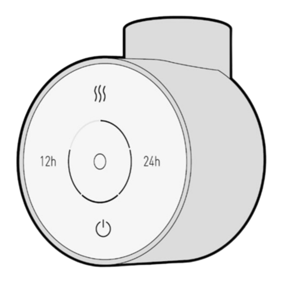
Any other use is strictly forbidden. The type of regulation consists of an ON-OFF electronic open- loop controller. SOLO can be connected to a fully electric towel dryer or a hybrid electric-hot water heater (dual fuel, central heating dryer). YMBOLS... - Page 7 Capacitive touchscreen interface displaying current system status (in black or white) Grub screw seat Position of the grub screw in order to fix SOLO to the Electric heating element connection Power supply cable 230 V power supply cable with plug...
-
Page 8: Technical Specification Tables
PECIFICATION ABLES SOLO and the electric heating element power must be carefully selected in proportion to towel rail size and thermal output. To select SOLO and the heating element electrical power, please refer to the el. dryer manufacturer instructions, when a certification related to the complete system (according to EN 60335-2-43) issued by an European recognized institute (like SEMKO, VDE, IMQ…) is available. -
Page 9: Installation - Qualified Technicians Only
5.1 Before you start • Avoid collisions during the handling. Do not deform SOLO. • Avoid the contact of cables and of parts of the SOLO with sharping corners and do not cause squashing. • Do not subject the cables to traction. Do not apply concentrated pressures on the SOLO surface. -
Page 10: Towel Rail Warnings
• Before installation, never switch the SOLO on to verify functioning effectiveness. • Don’t use the SOLO regulating box to lean the electrical towel rail on the floor as you can damage the plastic housing and water can penetrate inside with a risk of electrical shock. -
Page 11: Solo Position
600 mm above the floor (Figure 3). • Do not install SOLO into a towel rail fitted in ZONE 0 or ZONE 1 (Zone definition IEC 60364-7-701 in Figure 3). -
Page 12: Supply Cord Position
• SOLO must only be fitted vertically in the bottom part of the towel rail. • Electrical dryer must NOT be installed with the SOLO regulating box located at the top. This can seriously damage the control box and create a dangerous situation with a risk of fire. -
Page 13: Solo Installation
Insert SOLO into the electric heating element connection, applying slight pressure until SOLO is fully inserted. b. Keep SOLO pressed against the heating element in the towel rail and insert the provided grub screw into its spot; make sure there is no room between the device... - Page 14 Using the provided Allen key tighten the grub screw until it comes into contact and it is fully inserted in its spot, so that the SOLO is securely fixed to the electric heating element and the O-ring gasket is well in contact with both surfaces c.
-
Page 15: Cleaning
• The electrical dryer is intended only for drying towels washed in water. Any other use is forbidden • SOLO is intended to be used and installed into a towel rail. Any other use is strictly forbidden and potentially dangerous. - Page 16 • SOLO is intended to work only if the electric heating element - connected to SOLO and fitted into the towel rail - is completely immersed in the liquid (water) inside the el. dryer. • SOLO is designed for use with water or water + glycol filled el. dryers.
-
Page 17: Controller Functions
ONTROLLER UNCTIONS 7.1 Basic Operating modes and statuses... -
Page 18: Advanced Operating Modes
7.2 Advanced operating modes 7.2.1 12h TIMER functioning Configured power level (1-5) that repeats every 12 hours (for timer duration customization see 7.3). Use this mode if you wish to warm up your el. dryer at a configured power level automatically every 12 hours as shown below. -
Page 19: Timer Functioning
you can change the configured power level anytime while the icon is red (during timer functioning) without loosing the starting time of the timer. The device will save the last configured power level. even during 12 h timer you can activate BOOST mode 7.2.2 24h TIMER functioning Configured power level (1-5) that repeats every 24 hours (for timer duration customization see 7.3). -
Page 20: Settings And Other Functions
7.3 Settings and other functions 7.3.1 Power range setting Choose your preferred working power range among 5 different sets: SOLO will work within the power range you set (minimum power level is 20% in every set, maximum and intermediate power variates according to the table below). -
Page 21: Default Timer Duration In 12H-24H Timer
1- press and hold until starts flashing 2- tap and select your desired power range as shown in the table 3- tap to save on black display on white display 7.3.2 Default timer duration in 12h-24h timer Customizes timer duration of 12h and 24h timer In ANTIFREEZE mode: NOTE: after 10 seconds of no interaction, the device will go back to previous modality without saving any operation... -
Page 22: Lock Screen
on black display on white display 7.3.3 Lock screen In MANUAL, ANTIFREEZE or TIMER mode, limits the functioning to standby ON/OFF. In MANUAL, ANTIFREEZE or TIMER mode: press and hold together for 5 seconds until the device beeps twice • To unlock: Press and hold together for 5 seconds until the device beeps twice... -
Page 23: Maintenance
(turning off the switch is not sufficient). • Never try to modify or repair the SOLO in any of its parts by yourself. Never try to remove any part of the SOLO as water can penetrate inside the regulation box resulting in a risk of electrical shock. - Page 24 Never try to modify or repair the SOLO in any of its parts by yourself. Never try to remove any part of the SOLO as water can penetrate inside the regulation box resulting in a risk of electrical shock.
- Page 25 the product, will not apply to the reduced end of the cable and/or any terminal. The wiring of Class I equipment is as follows: Brown (black): phase 230 V / 50 Hz Blue: neutral conductor Yellow-green: protective conductor (earth) The manufacturer assumes no responsibility for any damage to the equipment or personal injury caused by improper installation of the cable, reversed polarity, insulation damage or any other intervention, connection or wiring that is not in compliance with the applicable regulations.
Need help?
Do you have a question about the SOLO and is the answer not in the manual?
Questions and answers