
Related Manuals for Kozyard Alicia

Summary of Contents for Kozyard Alicia
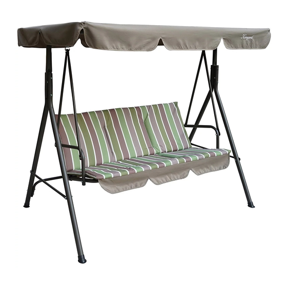
- Page 1 Alicia swing chair Assembly Manual Kozyard LLC Products © Copyright 2016 - 2023 Kozyard LLC. | All Rights Reserved. Version: 09182023...
-
Page 2: Important Notice
ASEEMBLY INSTUCTION BEFORE ASSEMBLING,MAKE SURE THAT YOU LAY OUT AND IDENTIFY ALL PARTS LISTED BELOW IN THE PARTS LIST. INSTALL ON LEVEL GROUND. INSTALL NOT LESS THAN 6 FEET FROM ANY OBSTRUCTION SUCH AS FENCE, GARAGE, HOUSE, OVERHANGING BRANCHES, LAUNDRY LINES,OR ELECTRICAL WIRES. TIGHTEN ALL NUTS AND BOLTS SECURELY. -
Page 3: Part List
Part list LEG TUBE TOP CROSS BAR TOP CROSS BAR LEG TUBE BACK LEG CROSS BACK LEG CROSS LEG CROSS HANGING PIPE E1X4 SEAT & BACK CUSHION ARMREST SPRING HOOK FRAME J1X1 CANOPY CANOPY TUBE CANOPY TUBE BOLT BOLT BOLT BOLT BOLT BOLT... - Page 4 Part list PLASTIC END PLASTIC SCREW WASHER ALLEN KEY WX21 ZX21 WRENCH...
- Page 5 STEP -1 Connect part D and part C to build the beam using bolt Q washer W, nut V and plastic end-cap Z as shown in diagram. W V Z STEP -2 Connect part A and part B with the beam using bolt U washer W, nut V and plastic end-cap Z as shown in diagram.
- Page 6 STEP -3 Connect part E and legs (part A&B) using bolt N washer W,nut V and plastic end-cap Z as shown in diagram. W V Z STEP -4 Connect part G and part F to build a connection tube for the rear foot using bolt O,washer X,nut W and plastic end-cap Z as shown in diagram.
- Page 7 STEP -5 Connect the rear foot tube with part B using bolt T washer W,nut V and plastic end-cap Z as shown in diagram. W V Z Connect part I and part J using bolt R washer W,nut V and STEP -6 plasticend-cap Z as shown in diagram.
- Page 8 1. Connect part E with backseat (part J1) using STEP -7 bolt S, washer X, nut W and plastic end-cap Z as shown in diagram. Z V W Z V W 2. Connect part E to armrest (part I) using bolt P, washer W, nut V and plastic end-cap Z as shown in diagram.
- Page 9 STEP -9 Affix part K to beam using screw Y. STEP -10 Insert part L to canopy.
- Page 10 STEP -11 Connect Part L and Part K to support canopy. STEP -12 Place cushion part J1 onto the frame. If it rains or snows, please remember to store cushion part J1 away. In the end, check that all screws are securely tightened before use.
- Page 11 866-355-0018...
Need help?
Do you have a question about the Alicia and is the answer not in the manual?
Questions and answers