Chapters
Table of Contents

Related Manuals for ATS VDO


Summary of Contents for ATS VDO
- Page 1 INSTRUCTION MANUAL Vacuum Degassing Oven This manual contains important operating and safety information. Carefully read and understand the contents of this manual prior to the operation of this equipment. www.atspa.com...
- Page 2 Applied Test Systems (ATS) 154 East Brook Lane Butler, PA 16002 Telephone: +1.724.283.1212 For assistance with set-up or operation, contact the ATS Service Department. Please have this manual and product serial number readily available when you call. © Copyright Applied Test Systems 2024...
-
Page 3: Table Of Contents
C.2 Product Description ........................14 C.3 Environmental Conditions ......................15 Verification Kit ............................16 Installation ..............................17 D.1 Assembling the VDO ........................17 D.2 Connecting and Powering Up ..................... 18 D.3 Vacuum Adjustment ........................18 Verification ..............................20 E.1 Verify Temperature ........................20 E.2 Verify Vacuum .......................... - Page 4 G.4 Controller Error ..........................28 G.5 Pump Error............................. 28 H. Maintenance............................29 H.1 Cleaning and Preventative Maintenance .................. 29 H.2 Spare Parts ............................ 29 APPENDIX A: Warranty .......................... 30 Appendix B: Wiring Diagram ........................31 Appendix C: Image Glossary ........................34...
-
Page 5: Introduction
A.2 – Warranty Information All new ATS systems are shipped with a warranty. Units have a warranty against defective parts and workmanship for one calendar year from the date of shipment. Please see APPENDIX A of this manual for complete details on the warranty. -
Page 6: Safety
Read and understand all instructions and safety precautions listed in this manual before installing or operating your unit. If you have any questions regarding the operation of the unit or instructions in this manual, contact the ATS Service Department at +1.724.283.1212. - Page 7 Disconnect power prior to performing maintenance. Turn off the unit and disconnect the line cord from the power source before performing any maintenance procedures. Hot / Burn surface, use Personal Protective Equipment (PPE) when operating the VDO, and handling materials associated with the testing procedure. Pinch Hazard...
- Page 8 Do not open the panel Unpack and operate on a stable surface. Installation of electrical devices must be accomplished by competent personnel and done in accordance with any current local and national codes. Equipment grounding is a MUST. Before energizing the electrical power to the Vacuum Degassing Oven, turn off all power switches and place all controls in an OFF position.
-
Page 9: Caution & Warning Locations
B.3 – Caution & Warning Locations iiFigure B.3.1 - Overhead View of Labels iiiFigure B.3.2 - Side View of Labels... -
Page 10: System Overview
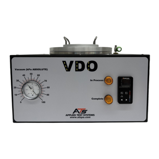
System Overview C.1 Equipment Parts Front of Unit ivFigure C.1.1 - Front of VDO Unit 1. Vacuum Gauge 4. Process Complete Indicator 2. Vacuum Lid with View Port 5. Vacuum Relief Valve 3. In Process Indicator 6. Controller... -
Page 11: Back Of Unit
Back of Unit vFigure C.1.2 - Back of VDO Unit 1. On / Off Switch 4. AC Power Connection 2. End of Test Alarm 5. Fan 3. Voltage Selector Switch 6. Data Tag (Make sure voltage is correct as stated on the Data Tag;... -
Page 12: Interior Chamber
Interior Chamber viFigure C.1.3 - Tank Interior viiFigure C.1.4 - Tank Exterior 1. O-Ring 4. Vacuum Pump Intake 2. Exhaust 5. Vacuum Verification Port 3. RTD 6. Vacuum Relief Valve... -
Page 13: Interior Controls
Interior Controls viiiFigure C.1.5 - Controls 1. Power Control 5. Pump Body 2. Fan 6. SSR (Solid State Relay) For Heaters 3. Solenoid 7. Watlow Temperature Controller 4. Relay For Vacuum Pump 8. Vacuum Gauge... -
Page 14: Product Description
Accessory Items • Specimen Containers (4 included with unit) • Specimen Removal Tool (included with unit) • VDO Verification Kit consisting of a Temperature Monitor, RTD Probe, VDO Chamber Cover, Vacuum Gauge, Brass Extension Fitting Parts, and Calibration Fixture (Figure C.2.1). -
Page 15: Environmental Conditions
C.3 Environmental Conditions The Vacuum Degassing Oven (VDO) should be kept in the following conditions, in an ideal setting: • Temperature of 15° C to 35° C • Relative humidity should not exceed 75% • Air pressure of 75 kPa to 106 kPa •... -
Page 16: Verification Kit
Verification Kit ixFigure C.2.1 - VDO Verification Kit 1. Resistance Temperature 4. Vacuum Gauge Detector (RTD) Probe 2. Temperature Monitor 5. Brass Extension Fitting Parts 3. Calibration Fixture 6. VDO Calibration Cover... -
Page 17: Installation
Installation D.1 Assembling the VDO Carefully remove the VDO from the packing crate and place it on a level work space. Make sure to remove any and all packing materials and / or accessories that may have been placed inside the vacuum chamber during shipment. -
Page 18: Connecting And Powering Up
15 kPa value. Utilize the conversion chart below to correct 15 kPa for your local altitude and barometric pressure. 2. After determining the corrected value, adjust the gauge installed on the VDO. Perform this by first removing the VDO top cover. Then rotate the gauge to align with 15 kPa. - Page 19 (or average) barometric pressure in your location and reference that to the pressure indicated in the gray-shaded columns on the table below. Applied Test Systems (ATS) assumes no responsibility to determining the proper ambient barometric pressure for your specific location and altitude.
-
Page 20: Verification
VDO and the temperature probe of the reference temperature measuring device being used to verify the temperature readout of the VDO. This is typically done by means of a brass block or other device suitable to create a stable thermal conductivity between the two devices. -
Page 21: Xvifigure E.1.4 - Placing Cover Over Oven
VDO to the setpoint temperature of 170°C. Allow at least 45 minutes to 1 hour for the VDO to heat and stabilize at the setpoint temperature of 170° C + / - 5 degrees C before taking any comparison readings. - Page 22 This value can be changed using the + and – keys. Change the value until the temperature display of the Watlow matches the calibrated thermometer within 0.1°C. 8. Allow the VDO temperature to stabilize at 170° C + / - 1.0° C, and repeat the verification process.
-
Page 23: Verify Vacuum
The instructions that follow are based on the assumption that the customer is using a relative pressure vacuum gauge to verify the vacuum readout of the VDO. If an absolute pressure gauge is being used to perform the verification process, the reading from the reference gauge may be directly compared to the readout of the VDO. - Page 24 3. Once the vacuum gauge is connected to the top of the VDO, unlock the temperature controller so that the vacuum can be manually turned on. Turn on the vacuum pump by going into the operations tab and turning on “Event 1”. Allow the pump to run until the vacuum does not drop any further and allow to stabilize.
-
Page 25: Operation
F. Operation F.1 Operation of VDO 1. Press the “POWER” button located on the back of the VDO. The Front display will light up. xxFigure F.1.1 - Power ON / OFF Switch 2. Press the left “Fn” button. This will preheat the unit to 170° C. This will take approximately 45 minutes to 1 hour. -
Page 26: Xxiifigure F.1.3 - Right "Fn" Button On Controller
6. At the end of 30 minutes when the process is complete, the pump will shut off, an audible alarm will sound along with test complete light. 7. The VDO is now ready to begin a new process. 8. Wearing high temperature gloves, carefully open the lid and remove asphalt samples from the Vacuum Degassing Oven (VDO) with specimen grips provided. -
Page 27: Troubleshooting
G.3 System Will Not Hold Vacuum 1. Check the O-Ring for damage and / or dirt. Also, inspect the bottom of the VDO lid for asphalt build-up or other debris and / or damage which could interfere with the O-Ring seal. -
Page 28: Controller Error
5. Verify the valve is closed. G.4 Controller Error 1. Do not attempt to fix independently. Contact the ATS Service Department by calling +1.724.283.1212. G.5 Pump Error 1. Do not attempt to fix independently. Contact the ATS Service Department by calling +1.724.283.1212. -
Page 29: Maintenance
2. It is also recommended to periodically apply a coating of vacuum grease to the O-Ring and O-Ring groove on the VDO oven. The bottom of the VDO lid should be inspected at this time for any signs of visible damage. -
Page 30: Appendix A: Warranty
APPENDIX A: Warranty Your Applied Test Systems product has been manufactured and inspected by experienced craftsmen. Applied Test Systems warrants, for the original purchaser, each product to be free from defects in material and workmanship for a period of thirteen (13) months from date of shipment or twelve (12) months from date of installation –... -
Page 31: Appendix B: Wiring Diagram
Appendix B: Wiring Diagram... -
Page 34: Appendix C: Image Glossary
B.3.2 - Side View of Labels ................9 ivFigure C.1.1 - Front of VDO Unit................10 vFigure C.1.2 - Back of VDO Unit ................11 viFigure C.1.3 - Tank Interior ..................12 viiFigure C.1.4 - Tank Exterior ..................12 viiiFigure C.1.5 - Controls ....................
Need help?
Do you have a question about the VDO and is the answer not in the manual?
Questions and answers