Table of Contents
Advertisement
Quick Links
Advertisement
Table of Contents

Related Manuals for ATS RTFO


Summary of Contents for ATS RTFO
- Page 1 INSTRUCTION MANUAL RTFO Rolling Thin Film Oven This manual contains important operating and safety information. Carefully read and understand the contents of this manual prior to the operation of this equipment. www.atspa.com MAN - RTFO - REV: Org...
- Page 2 154 East Brook Lane Butler, PA 16002 Telephone: +1-724-283-1212 For assistance with set-up or operation, contact the ATS service department. Please have this manual and product serial number available when you call. © Copyright Applied Test Systems 2019 MAN - RTFO - REV: Org...
-
Page 3: Table Of Contents
D.3 Setting the Temperature .............................12 D.4 Leveling the Machine ............................13 E. Verification ..........................14 E.1 Temperature Verification ............................ 14 E.2 Verification of Air Flow ............................14 F. Operation ............................. 15 F.1 Basic Operation ..............................15 G. Troubleshooting ......................... 16 MAN - RTFO - REV: Org... - Page 4 H.3 Bearing Service and Replacement ........................20 H.4 Chain Maintenance .............................22 H.5 Tray Cleaning ..............................22 H.6 Replacement Parts and Accessories .........................23 Appendix A: Warranty ........................25 Appendix B: Wiring Diagram ......................26 Appendix C: Image Glossary ......................30 MAN - RTFO - REV: Org...
-
Page 5: Introduction
Retain all cartons and packing materials until the unit is operated and found to be in good condition. If damage has occurred during shipping, notify Applied Test Systems (ATS) and the carrier immediately. If it is necessary to file a damage claim, retain the packing materials for inspection by the carrier. -
Page 6: Safety
Read and understand all instructions and safety precautions listed in this manual before installing or operating the unit. If there are any questions regarding operation of the unit or the instructions in this manual, contact the ATS service department at +1-724-283-1212. -
Page 7: Warnings
WARNING: Do not open the side panel unless explicitly instructed to do so for troubleshooting purposes. WARNING: Do not use flammable solvents to clean the oven or use with products other than designed for. MAN - RTFO - REV: Org | B. Safety... -
Page 8: Cautions
CAUTION: The RTFO must be grounded and wired in accordance with national and local electrical code requirements. CAUTION: Before energizing the electrical power to the RTFO, place all controls in an OFF position. CAUTION: Do not exceed the maximum operating temperature. -
Page 9: System Overview
C.1 General Description The RTFO provides a controlled flow of heated air directed into the openings of horizontal glass bottles as they rotate on a carousel rack, simulating short term aging of binder during production, handling, and paving operations. It exceeds ASTM D2872, AASHTO T 240, and California 346 testing standards with a 5 to 8 minute recovery time. -
Page 10: Rtfo Layout
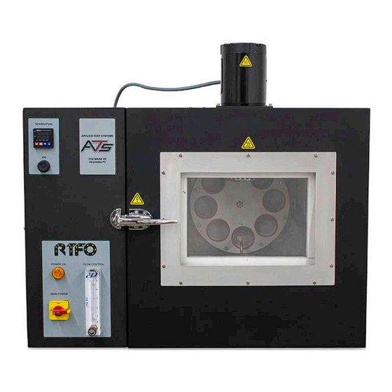
Figure C.1: RTFO Front 1. Temperature Controller 6. Flow Meter 2. Fan Motor 7. Carousel with High Temp. Silicone Rings 3. Carousel Jog Button 8. Leveling Legs 4. Power Indicator 5. Power Switch MAN - RTFO - REV: Org | C. System Overview... -
Page 11: Rtfo Back
Back of Unit Figure C.2: RTFO Back 1. Cooling Fan 3. Power Inlet Module 2. Air Inlet/Input Filter MAN - RTFO - REV: Org | C. System Overview... -
Page 12: Rtfo Chamber
Interior Chamber Figure C.3: RTFO Chamber 1. Internal RTD 5. Air Oriface 2. Fan 6. Airline Plumbing 3. Carousel 7. Tray 4. Jar Holder 8. Heaters (located under tray) MAN - RTFO - REV: Org | C. System Overview... -
Page 13: Panel Layout And Components
4. Blower Drive 9. Circuit Breaker 5. Sample Rack Drive 10. Sample Rack Motor *Fuses 1 & 2 for 24VDC Supply **Fuse 3 for Blower ***Fuse 4 for Sample Rack MAN - RTFO - REV: Org | C. System Overview... -
Page 14: Temperature Controller
DOWN BUTTON: Press the DOWN button to decrease values displayed on the SV display. Hold down this button to speed up the decrement. UP BUTTON: Press the UP button to increase the values displayed on the SV display. Hold down this button to speed up the increment. MAN - RTFO - REV: Org | C. System Overview... -
Page 15: Installation
2. The oven has been completely tested and checked at ATS before shipment. A power cord 10 feet long is supplied with the oven. The end user is required to supply a plug and receptacle rated for 10 Amp, 240 Volt, single phase, electrical service. -
Page 16: Setting The Temperature
D.3 Setting the Temperature 1. To change the RTFO temperature set point, press and hold the UP and DOWN arrow buttons at the same time until the GREEN SV temperature display begins to blink. 2. Hold the UP arrow button to increase temperature or the DOWN arrow button to decrease temperature until the desired set point is reached. -
Page 17: Leveling The Machine
D.4 Leveling the Machine 1. Using a digital level check the level on the top of the RTFO and the bottom portion of the RTFO for a reference point. 2. Insert the leveling jar into the carriage to check the level at different points of rotation. The level should be +/- 1.0 degrees from the reference point. -
Page 18: Verification
E.2 Verification of Air Flow 1. Attach a flow verification device to the copper tubing inside the RTFO (Sec. C.2, Fig. C.3) (if using a flow through device the orifice can be removed from the tubing and attached to the downstream end). -
Page 19: Operation
RTFO and handling materials associated with the testing procedure. 1. Turn the power switch on the front of the Rolling Thin Film Oven (RTFO) to the ON position. The POWER light located on the front of your RTFO will light up and the temperature controller display will power on. -
Page 20: Troubleshooting
RTFO. Users may follow the steps provided to work through these basic errors. WARNING: Any additional issues or system errors should be brought to the attention of the ATS Service Department immediately. Please do not attempt to independently fix any other system errors. -
Page 21: Carousel Will Not Rotate
G.3 Carousel Will Not Rotate When the unit is powered on and the RTFO door is closed, the fan should rotate continuously. The carousel will only start rotating once the unit is in the run cycle mode (when a test is running). -
Page 22: Fan Motor Will Not Rotate
8. If the carousel still will not rotate, contact the ATS Service Department at +1-724-283-1212. G.4 Fan Motor Will Not Rotate When the unit is powered on and the RTFO door is closed, the fan should rotate continuously in a counter clockwise direction as viewed from above. -
Page 23: Unit Will Not Heat
4. If the unit still has no air flow please contact the ATS service department at +1-724-283-1212. G.6 Unit Will Not Heat 1. Verify that there is power to the unit - refer to (Sec. G.2). 2. If the unit still will not heat, check the temperature controller on the front of the unit to verify that it is turned on and that the SV temperature is higher than the PV temperature. -
Page 24: Maintenance
H.1 Cleaning the Unit Before cleaning the RTFO, unplug the machine and allow it to cool. Always wear personal protective gear and clean using Acetone. Do not use any other flammable solvents to clean this machine. Allow equipment to sit, with door open, for a minimum of 15 minutes before further use to allow any vapors from the cleaning solvent to dissipate. - Page 25 7. Remove the four 1/4-20” x 3/4” bolts retaining the bearing and shaft assembly, then slide the assembly out of the RTFO (Fig. H.8). 8. Replace bearing and shaft assembly with new assembly and return the damaged assembly to ATS Service. Figure H.2: Retaining Screw Figure H.3: Removing the tray...
-
Page 26: Chain Maintenance
2. Remove the rear cover (Fig. H.6). 3. Proper chain tension is required for reliable operation of the RTFO and ensures long life of the bearings. The chain should not be tightened to the point where it is in tension and should not be loosened to the point where it visibly sags (Fig. - Page 27 4. The heating element coils underneath the tray are extremely sensitive and do not require regular cleaning (Fig. H.11). Any materials that may drip onto the coils will burn off gradually over time. Any additional cleaning may damage the coils. MAN - RTFO - REV: Org | H. Maintenance...
-
Page 28: Replacement Parts And Accessories
Fuse, Class CC, 10A, 600 V (Fig. C4, Items 2 and 3) ELE6111 Fuse, Class MDL, 1A, 250V (Fig. C4, Item 1) 103693 Heating element assembly 4-13492 Silicon gasket for specimen wheel MAN - RTFO - REV: Org | H. Maintenance... -
Page 29: Appendix A: Warranty
The aforementioned provisions do not extend the original warranty period of any article that has been either repaired or replaced by Applied Test Systems. Applied Test Systems reserves the right to change published specifications. MAN - RTFO - REV: Org | Appendix A: Warranty... -
Page 30: Appendix B: Wiring Diagram
Appendix B: Wiring Diagram MAN - RTFO - REV: Org | Appendix B: Wiring Diagram... - Page 31 MAN - RTFO - REV: Org | Appendix B: Wiring Diagram...
- Page 32 MAN - RTFO - REV: Org | Appendix B: Wiring Diagram...
- Page 33 MAN - RTFO - REV: Org | Appendix B: Wiring Diagram...
-
Page 34: Appendix C: Image Glossary
Figure H.8: Bearing and shaft assembly mounting bolts ..................... 21 Figure H.9: Chain is too loose............................22 Figure H.10: Chain is properly tensioned........................22 Figure H.11: Heating element coils ..........................23 MAN - RTFO - REV: Org | Appendix C: Image Glossary...
Need help?
Do you have a question about the RTFO and is the answer not in the manual?
Questions and answers