Table of Contents

Subscribe to Our Youtube Channel
Related Manuals for Centrometal Cm Pelet-set 90

Summary of Contents for Centrometal Cm Pelet-set 90
- Page 1 CENTROMETAL d.o.o. – Glavna 12 – 40306 Macinec – Croatia tel: +385 40 372 600; fax : +385 40 372 611 TECHNICAL INSTRUCTIONS FOR THE COMMISSIONING AND ADJUSTMENT Cm Pelet-set (60-90 kW) For boilers: EKO-CK P 70-110 TUPS-90-M-01-2017-E-N-eng...
-
Page 2: Table Of Contents
1. Introduction ...…………………………………………………………………………………………….. 2. Status at delivery ………………………………………………………………………………………… 3. Technical data …………………………………………………………………………………………… 4. Installation of Cm Pelet-set 90.……………………………………………………………..………….. 4.1. Installation of pellet burner and pellet control unit on boiler ..……………..…………... 4.2. Installation of pellet tank CPSP-800 and pellet feeder CPPT-90…………………..….. -
Page 3: Introduction
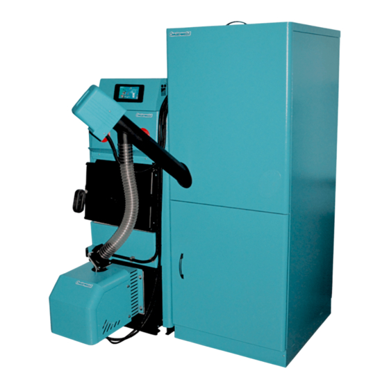
Technical instructions for the commissioning and adjustment 1. Introduction Cm Pelet-set 90, pellet based heating system (nominal burner output 60 to 90 kW) designed for installation in combined boilers or biomass firing boilers EKO-CK P, with thermal output from 70 to 110 kW. -
Page 4: Installation Of Cm Pelet-Set
70) and CPDV 90/110 (for boilers EKO-CK P 90 i 110) 4. Installation of Cm Pelet-set 90 Commissioning and fine adjustment of Cm Pelet-set 90 should be carried out by a professional or the manufacturer’s authorized fitter. 4.1. Installation of pellet burner and pellet control unit on the boiler... - Page 5 Technical instructions for the commissioning and adjustment...
- Page 6 Technical instructions for the commissioning and adjustment c) Drill 2 holes at the distance of 358 mm on the top side of boiler plating, and using enclosed screws 3.9 x 9.5 mm fix boiler control unit CPREG, insert the safety thermostat sensor and control unit sensor into the sleeve on the boiler (on the top side on EKO-CK P boiler) and connect wires by 4-poles and 6-poles connectors onto the burner and then fix the connectors to the burner body.
- Page 7 Figure 1a. Connection scheme of the boiler EKO-CK P 70,90 and 110 with in-built Cm Pelet-set 90 on heating installation with stainless steel hot water boiler: 1. Boiler EKO-CK P 70,90,110 with in-built Cm Pelet-set 90 2. Stainless steel hot water boiler TB 3.
-
Page 8: Installation Of Pellet Tank Cpsp-800 And Pellet Feeder Cppt-90
Cm Pelet-set 60 = 24 Pa Cm Pelet-set 70 = 25 Pa Cm Pelet-set 90 = 28 Pa 6. Boiler control unit Boiler control unit is supplied in a plasticized metal box prepared for installation on boilers EKO-CK P 70, 90 and 110. -
Page 9: Symbol Description
Technical instructions for the commissioning and adjustment 6.2. Symbol description Indication of operation of the sanitary water heating pump Indication of operation of the heating pump circuit. Indication of turn on status of timer (time programmes).. Indication of operation of pellet feeding screw feeder Indication of flame presence in the burner Indication of operation of the burner fan. -
Page 10: The Basic Software Configuration
Technical instructions for the commissioning and adjustment 6.4. The basic software configuration (by authorized service) It is used for the case: - on CentroPlus/-B boiler firing with solid fuel / pelets: adjusting the temperature of the boiler for the first firing a pellet burner (for CentroPlus /-B boilers fired with solid fuel / wood pellets) when working on wood without accumulation tank (CAS) - adjust the maximum temperature in the accumulation tank (CAS) for the first firing a pellet burner (if accumulation tank (CAS) is installed). - Page 11 Technical instructions for the commissioning and adjustment accumulation tank sensor it is necessary to set at the lowest sensor sleeve on the last accumulation tank (CAS) or in sensor sleeve below the level that we want to heat up in accumulation tank (CAS). OP03 - Switch off of pump to accumulation tank (CAS) Factory setting: "0"...
-
Page 12: Fine Tuning Of Operating Parameters Of The Burner
Technical instructions for the commissioning and adjustment OP07 - Work with external controller or remote control "telecontrol" Factory setting: "0" (turned off) Available setting: "0" (turned off), "1" (turned on). "OP07" can be turned on ("1") if "OP01" and "OP02" is turned off. - Page 13 Technical instructions for the commissioning and adjustment Pr08: PIN entry Factory setting: OFF (turned off) Available setting: Pin (turned on) When ''+'' button is pressed, ‘’PIN’’ is displayed in the lower display, and after that PIN can be entered; PIN enables to enter the burner setting menu.
- Page 14 Technical instructions for the commissioning and adjustment Overview of the burner current mode When the burner reached the set programme, when ''-'' button is pressed, the current burner output and current burner sub-mode (for example, P6 1, P4 2, P2 3…) are displayed in the lower display and 0000 is displayed in the upper display.
- Page 15 Technical instructions for the commissioning and adjustment The table below shows times in seconds (sec.) and revolution number per minute (rpm) of individual parameters with factory settings and available setting range CPPL-90 TABLE WITH FINE TUNING OF BURNER OPERATING PARAMETERS Param.
-
Page 16: Burner Operation Modes
Technical instructions for the commissioning and adjustment 0- suction system is not installed FP37* Suction system configuration 1- suction system installed 1 – 20 sec FP38* START time 5 sec 1 – 360 sec FP39* RUNNING time 45 sec 1 – 60 sec FP40* END time 10 sec... - Page 17 Technical instructions for the commissioning and adjustment Fan turns off and heater turns on. After expiry of FP5 time, it goes to Mode A2. If '-' is pressed, A1 Mode is displayed in the lower display and time to FP5 is counted down in the upper display.
- Page 18 Technical instructions for the commissioning and adjustment Fan works at FP25 speed. Screw alternately turns on (FP15) and turns off (FP16) until FP33 time expires and then goes to Mode PP3. If '-' is pressed, PP2 Mode is displayed in the lower display and time to FP15 or FP16 is counted down in the upper display.
- Page 19 Technical instructions for the commissioning and adjustment Mode A6: Fan works at speed: FP28+FP30 if control unit output is P5 FP29+FP30 if control unit output is P6 Upon expiry of FP31 time, control units goes to Mode PX, wherein X control unit output is set. Screw alternately turns on and turns off as at PPX.
-
Page 20: Interruption Of Power Supply
Technical instructions for the commissioning and adjustment 7. Power supply interruption If power supply is interrupted while the burner is operating (what can also occur because of opening the lower boiler door while the burner is working), regardless the phase it has been operating in, upon resume of supply, the burner starts with firing phase (without feeding), of max. - Page 21 Technical instructions for the commissioning and adjustment ELECTRICAL REGULATION SHEME...
- Page 22 BURNER - CIRCUIT DIAGRAM/ADAPTER FOR ZONE REGULATION Centrometal d.o.o. shall not be responsible for possible incorrect data caused by printing errors or errors during transcription and in any case, it reserves the right to modify its products deemed to be required and useful, without any prior notification...
Need help?
Do you have a question about the Cm Pelet-set 90 and is the answer not in the manual?
Questions and answers