Table of Contents
Advertisement
Quick Links
Advertisement
Table of Contents

Related Manuals for Spectrafy SolarSIM-G


Summary of Contents for Spectrafy SolarSIM-G
- Page 1 User Manual: Solar Spectral Irradiance Meter SolarSIM-G © Spectrafy, 2024...
- Page 2 Tel: 1-613-237-2020 info@spectrafy.com www.spectrafy.com Spectrafy reserves the right to make modifications to the user manual without prior notice. Warranty and liability Spectrafy guarantees that the Solar Spectral Irradiance Meter (SolarSIM-G) has been thor- oughly tested to ensure that it meets all of the stated specifications. A two year warranty is provided from date of invoice, subject to correct installation and operation.
-
Page 3: Table Of Contents
4 Connectivity 4.1 SolarSIM-G Communication Box ......4.2 Serial-over-Ethernet converter ...... - Page 4 Dimensional drawing of a mounting plate....The SolarSIM-G COMBOX......
-
Page 5: Introduction
Spectrafy. Please become familiar with this instruction manual for a full understanding of the use of your SolarSIM-G. The SolarSIM-G is designed to be a cost-effective tool for accurately determining the solar spectrum and global horizontal/tilted irradiance (GHI/GTI) as part of on-site solar resource assessments and module performance characterization studies. -
Page 6: Main Components
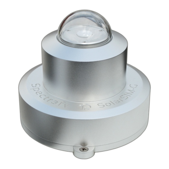
1 Main components The side view of SolarSIM-G components is shown in Figure 1, which includes • a glass dome, • an enclosure, • bandpass filters, • bubble level, • a connector, and • a backplate. Figure 1: SolarSIM-G components and main dimensions. -
Page 7: Glass Dome
Nine hard-coated bandpass filters transmit a narrow band of spectral irradiance to the de- tectors. 1.4 Bubble level The bubble level ensures the SolarSIM-G is leveled when measuring the irradiance in the global horizontal orientation. 1.5 Connector The connector provides the power and communication to the SolarSIM-G. -
Page 8: Installation
1. Place the SolarSIM-G on the mounting plate as per Figure 3. 2. Place the spring under the SolarSIM-G so that it roughly aligns with one of the mounting holes on the SolarSIM-G. 3. Insert the mounting screw through the SolarSIM-G’s mounting hole and the spring. -
Page 9: Assembled Solarsim-G On A Mounting Plate
Figure 2: Assembled SolarSIM-G on a mounting plate. Figure 3: Dimensional drawing of a mounting plate. -
Page 10: Maintenance
The SolarSIM-G requires very little maintenance. The most important task is to make sure that the glass dome of the SolarSIM-G is clean at all times, as the accumulation of dirt can lead to misrepresented data. Furthermore, the horizontal alignment of the SolarSIM-G should be checked periodically. -
Page 11: Connectivity
Option 1 uses the SolarSIM Communication Box (COMBOX) - a seamless link between a PC and the SolarSIM-G, as shown in Figure 4. A standard 6 ft USB cable is connected from the COMBOX to a PC. On the other side, a 10 m RS-485 communication cable is connected from the COMBOX to the SolarSIM-G. -
Page 12: Solarsim-G Communication Box
6. Once the FTDI drivers are installed, restart the PC. 4.2 Serial-over-Ethernet converter For remote test site applications the SolarSIM-G can be connected to a networked PC via a suitable serial-over-Ethernet (SOE) converter - such as the ICP DAS I-7188-E2 . -
Page 13: Server Configuration For Vxcomm Software
Figure 5: Server configuration for VxComm software. Note, the SolarSIM-G supports only the ASCII RS-485 communication mode. Figure 6: Port configuration for VxComm software. Note, the SolarSIM-G supports only the ASCII RS-485 communication mode. -
Page 14: Datalogger
4.3 Datalogger The connectivity with a datalogger is similar to the SolarSIM-G’s integration with the SOE converter. The SolarSIM-G communication cable is connected to the corresponding datalog- ger inputs as per Section 4.2. The datalogger must have a spare RS-485 port. -
Page 15: Adjustment Of The Solarsim-G User Settings
The sets the data acquisition resolution for the entire SolarSIM-G data set, while the sampling rate determines how often to poll the measurements over the duration of the DAQ rate. If... -
Page 16: Using The Software
Once launched, the program automatically searches for the SolarSIM-G calibration file. If the SolarSIM-G DAQ detects multiple calibration files, the application will prompt the user to select the serial number of the desired SolarSIM-G, as shown in Figure 10. -
Page 17: Browsing To The Calibration File
Figure 9: Browsing to the calibration file. Figure 10: Selecting multiple calibration files. Figure 11: Failing to detect the SolarSIM-G. Figure 12: Changing and verifying geographic settings. -
Page 18: Data Type And Storage
, and correspond to the year, month, and day, respectively. A snippet of the SolarSIM-G spectrum file is presented in Figure 14. As shown, the wavelength column is not included in order to minimize the file size. Rather the 3721 values of the spectral irradiance in units of W/m /nm are presented in a single column format. -
Page 19: Data Collection Size
Custom spectrum timer Spectrum timer The user is advised to use the options in the user settings.conf file to reduce the daily spectral data set size as desired. Figure 14: SolarSIM-G spectrum data file snippet. Figure 15: SolarSIM-G daily summary file snippet. -
Page 20: Changing Default Language For Non-Unicode Characters
5.6 Changing default language for non-Unicode characters For users of computers with non-Latin based languages, such as Mandarin, the SolarSIM-G DAQ may improperly display non-Unicode characters. To solve this problem, the user must change the default language for non-Unicode programs to English. To do so, first locate the... -
Page 21: Changing The Default Language For Non-Unicode Characters
Figure 18: Changing the default language for non-Unicode characters.. -
Page 22: Datalogger Setup
SolarSG software. 6.1 Serial port configuration Prior to configuring the serial port on a datalogger, the user must wire the SolarSIM-G by following instructions from Section 4.2. The serial port is then configured with standard serial parameters as per Table 3. -
Page 23: Processed Output Example For Nxxxx E Command
N1010 2500.000,1013.120,4750.000,2600.000,1050.000,2500.032,4999.999, 0000.001,1274.004,2746.321,3291.214, 3924.385,1900.500,0500.123/r/n The aforementioned string can be parsed as: N\serial number" \ ",\ ",\ ",\ ",\ ", + 50) + 50) ",\ ",\ ",\ ",\ ",\ ",\ ",\ ",\ ",\end of line character" where , and are the ambient temperature, the ambient pressure, the ambient humidity, the internal temperature, the internal humidity, and the nine voltages from the detectors, respectively. -
Page 24: Raw Data File Format
6.3 Raw data file format The SolarSG software requires a .csv file in a specific format based on the SolarSIM-G raw data output. The file must have the following headings with the corresponding data: Timestamp Time zone (hr) Ambient pressure (kPa) -
Page 25: Solarsg Application
The SolarSG application is an executable that the user must run to process the raw data from the SolarSIM-G into the spectral data. This software is located on the provided USB key inside a folder with contents as per Figure 20, which initially include: atmParam.data... -
Page 26: Appendix: Using The Solarsg Application
Appendix: Using the SolarSG Application... - Page 27 1. Introduction The SolarSG application has two functions: 1) To process batches of SolarSIM raw data .csv files. The processed data is output and stored as daily summary files and per-timestamp spectral files. 2) To process raw data for a single timestamp using a command line or equivalent interface.
- Page 28 5. Double-click the SolarSG application – it will start processing the raw data. 6. Processed data will be stored in the folder “~\Processed Data\Direct” “~\Processed Data\Global” within the SolarSG Folder for the SolarSIM-D2 or SolarSIM-G, respectively. a. If nothing happens, check the error logs to make sure everything is set up properly.
- Page 29 3. Processing raw data for a single timestamp 1. Create a folder (SolarSG) and place the SolarSG executable,SSIM_calibration_SNxxx, atmParam.data, and user_settings files in it Fig. 4. SolarSG folder showing SolarSG executable, SSIM_Calibration_SNxxx, atmParam.data and user_settings files are all present. 2. Open the user_settings.ini file in a text editor and make sure the AutoMode parameter is set to 1.
- Page 30 Command line input to generate processed data without a spectrum: ~/ SolarSG.exe “yyyy-mm-dd hh:mm:ss, timezone,ambient_temperature,ambient_pressure,ambient_humidity,internal_temperature, internal_humidity,V1,V2,V3,V4,V5,V6,V7,V8,V9,-1,C:\filepath\to\calibration_file.json” SolarSIM-G output data string format: “yyyy-mm-dd hh:mm:ss,timezone,elevation,azimuth,ambient_temperature,ambient_pressure, ambient_humidity,internal_temperature,internal_humidity,GHI” SolarSIM-G output data string format with precipitable water vapour (PWV) upgrade: “yyyy-mm-dd hh:mm:ss,timezone,elevation,azimuth,ambient_temperature,ambient_pressure, ambient_humidity,internal_temperature,internal_humidity,GHI,PWV” Note, the PWV value is reported in mm.
Need help?
Do you have a question about the SolarSIM-G and is the answer not in the manual?
Questions and answers